The Building of a Torpedo Tube Begins with the Barrel
16
The Mechanisms which Convert the Barrel into a Torpedo Tube
19
15
The Building of a Torpedo Tube begins with the BARREL
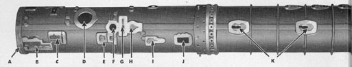
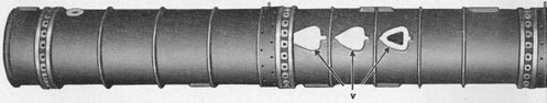
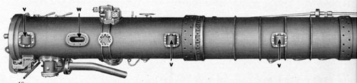
Figure 12 TOP OF TUBE BARREL
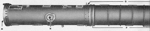
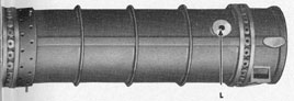
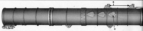
Figure 13 INBOARD SIDE OF TUBE BARREL
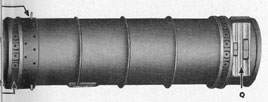
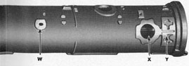
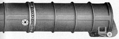
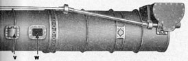
Figure 14 BOTTOM OF TUBE BARREL
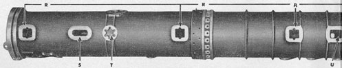
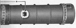
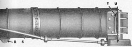
Figure 15 OUTBOARD SIDE OF TUBE BARREL
A
Acme thread to engage breech door locking ring.
B
Interlocking mechanism breech bracket pad.
C
Stop cylinder and pilot valve pad.
D
Poppet valve pad.
E
Gyro spindle retraction mechanism pad.
F
Vent pad (after vent on bow tubes; forward vent on stern tubes).
G
Tripping latch pad.
H
Depth setting mechanism pad.
I
Speed setting pedestal pad.
J
Speed setting housing pad.
K
Torpedo stop pads (stop bolt assembly is interchangeable from one to the other, according to Mark torpedo used).
L
Vent pad (forward vent on bow tubes; after vent on stern tubes).
M
Locking ring for breech door.
N
Gyro setting mechanism pad.
O
Joints.
P
Bulkhead rings.
Q
Muzzle door hinge bracket.
16
Figure 12 TOP OF TUBE BARREL
Figure 13 INBOARD SIDE OF TUBE BARREL
Figure 14 BOTTOM OF TUBE BARREL
Figure 15 OUTBOARD SIDE OF TUBE BARREL
R
Roller bracket pads.
S
Drain pad (after drain on bow tubes; forward drain on stern tubes).
T
Stanchion pad.
U
Drain pad (forward drain on bow tubes; after drain on stern tubes).
V
Roller trip, or roller crank, pads (only one used).
W
Poppet valve operating unit pad.
X
Firing valve pad.
Y
Breech door hinge bracket pad.
Torpedo tube barrels are constructed out of three
sections, which are bronze castings, and known as
the breech, middle, and muzzle sections, these three
sections being joined together to form a continuous
cylinder. In joining, the three sections are forced
together, cold riveted, and sealed with solder.
In some tubes in earlier submarines, the barrel is
of the same thickness throughout, except where
bosses and pads are cast on to receive various fittings
or parts of the operating mechanism. In submarine
torpedo tubes of current construction, however, the
interior finish is maintained on only four surfaces
or "lands" (top, bottom, and both sides), the rest
being recessed. In all cases, however, the finished in
side diameter of the tube is 21.125 inches.
The bosses and pads cast on the barrel to receive
the various fittings or parts of the operating mechanism, are shown in the keyed illustrations at the left
(Figures 12, 13, 14, and 15). These four views show
the barrel for a lower port bow tube. In the first
three, the barrel has been turned over to show, first,
the top, then the inboard side, then the bottom. In
the lower view, Figure 15, the barrel has been turned
around, end for end, to show the outboard side.
The pads and bosses include the following: Breech
door hinge bracket pad; firing valve pad; poppet
valve operating mechanism pad; roller trip pads
(only one of these being used, the Mark of torpedo
to be fired from the tube determining which one)
vent pad (as shown, the forward vent on bow tube,
after vent on stern tube); torpedo stop pads (the
stop bolt being interchangeable from one to the
other, according to the Mark of torpedo loaded)
speed setting mechanism pad; depth setting mechanism pad; tripping latch pad; vent pad; stop cylinder and valve pad; interlocking mechanism breech
bracket pad; poppet valve pad; acme thread, which
17
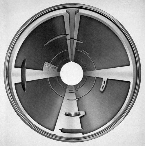
Figure 16-Interior of Barrel
engages a similar thread in the breech door locking
ring; roller bracket pads; drain pad (as shown,
forward vent on bow tube, after vent on stern
tube); stanchion pad; drain pad (as shown, after
drain on bow tube, forward drain on stern tube)
muzzle door hinge bracket pad; joints; bulkhead
rings; gyro setting mechanism pad; and locking
ring for breech door.
The significance of each of these bosses and
pads, and their relation to the torpedo tube as a
whole, as well as to its operation, will be more
fully explained in their proper order on the following pages of this pamphlet.
Figure 16 shows a view of the interior of the
18
barrel as it is finished with the four raised positions
known as lands. This construction lightens the
weight of the tube, and reduces the amount of machining necessary to finish the tube to the diameter
of 21.125 inches. Obviously, the four points of contact provided by the lands are sufficient to hold a
torpedo in proper position. However, the torpedo
does not rest upon the bottom land, but upon the
four rollers along the bottom of the tube.
Current torpedo tubes are of two lengths, bow
tubes being 252 inches, stern tubes 276 inches, over
all length, not including doors. The effective length
(the greatest length of the torpedoes that can be
loaded into the barrel) for a barrel 252 inches
over-all would be 250.81 inches; for a barrel 276
inches over-all, the effective length would be 274.81
inches.
Running through the top inside surface, or land,
is a guide slot, 1 3/16 inches in width (as shown in Figure 16) which engages the guide stud on top of a torpedo to prevent it rotating while being ejected from
the barrel, also to insure matching between the depth
setting, speed setting, and gyro setting mechanisms
on the tube and the sockets for the corresponding
mechanisms in the torpedo.
Along the bottom of the barrel are four rollers,
mounted in brackets bolted to the bottom of the
barrel. These rollers support the torpedo, and facilitate its movement while being loaded into and
ejected from the barrel. In other words, the torpedo
rides on these rollers during its movement through
the barrel. Each roller bracket has a drain connection to prevent retention of water.
In some earlier torpedo tubes, a relief valve was
fitted near the muzzle end of the barrel to vent the
barrel whenever its pressure exceeded the pressure
of the sea by more than ten pounds per square inch,
and thereby prevent injury to the hinge of the muzzle door. It has been found, however, that under
such pressure differentials the tube will vent
through the muzzle door without injury to any
part, so such valves are no longer fitted on tubes.
The MECHANISMS Which Convert the Barrel into a TORPEDO TUBE
Obviously there must be something more than
merely the barrel to make a torpedo tube an effective weapon for firing torpedoes. Various mechanisms, each of which has a specific function to perform yet is closely interrelated to all the others,
must be added to the barrel in order to convert it
into a torpedo tube.
These mechanisms, some of which have been
briefly referred to in the foregoing pages showing
the pads and bosses on the barrel, control the opening and closing of the breech and muzzle doors;
set the speed setting, the depth setting, and the gyro
setting mechanisms in the torpedo; admit the
charge of compressed air which fires the torpedo out
of the tube; vent the air off before it has a chance
to escape into the sea and disclose the position of
the submarine to the enemy; drain the water from
the tube after a torpedo has been fired, and perform
other necessary functions.
The position or location of these various mechanisms on the tube are shown, not necessarily in their
proper order or relationship, in the keyed
19
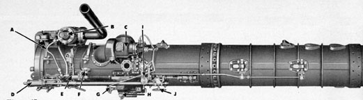
Figure 17 TOP OF TUBE
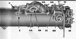
Figure 18 INBOARD SIDE
Figure 19 BOTTOM OF TUBE
Figure 20 OUTBOARD SIDE
A
Tripping latch arm.
B
Firing valve.
C
Poppet valve.
D
Interlocking mechanism breech bracket.
E
Firing mechanism stop cylinder, pilot valve, and shutter bar.
F
Electric firing solenoid.
G
Poppet valve indicator.
H
Gyro setting mechanism.
I
Depth setting mechanism.
J
Speed setting mechanism.
K
Interlocking mechanism breech bracket.
L
Interlocking mechanism levers.
M
Hand firing key.
N
Gyro setting mechanism.
O
Depth setting mechanism crank.
P
Speed setting wheel.
Q
Torpedo stops (also see K in Figure 20).
R
Roller brackets.
S
Muzzle door operating shaft.
T
Muzzle door hinge bracket.
U
Housing for muzzle door operating gears.
V
Roller brackets (also see R in Figure 18).
W
Torpedo tube drain pipes fasten here.
X
Torpedo stops (also see Q in Figure 18).
20
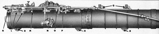
Figure 17 TOP OF TUBE
Figure 18 INBOARD SIDE
Figure 19 BOTTOM OF TUBE
Figure 20 OUTBOARD SIDE
Y
Roller trip, or roller crank, housing.
Z
Poppet valve operating mechanism.
AA
Tripping latch shaft.
BB
Flange for poppet valve drain pipe.
CC
Flange for impulse air pipe.
DD
Check valve.
EE
Breech door bracket.
FF
Firing valve.
GG
Electric firing solenoid.
HH
Poppet valve.
II
Depth setting mechanism.
illustrations, Figures 17, 18, 19, and 20, at the left. They
include the following:
A-Tripping latch arm, connects from cam on
breech door hinge to operating shaft, and raises or
lowers the tripping latch which trips the starting
lever on the torpedo as it leaves the tube.
B-Firing valve, releases charge of compressed air
into the tube to shoot the torpedo out of the tube.
C-Poppet valve, which draws off the charge of
compressed air that shoots the torpedo out of the
tube before the air can escape into the sea and create
a disturbance on the surface of the water which
would disclose the location of the submarine.
D-Interlocking mechanism breech bracket, the
central point of the interlocking mechanisms which
prevent improper operation of the tube.
E-Firing mechanism stop cylinder and pilot valve,
into which air is admitted by the stop cylinder valve
to set off the firing valve; with the interlock shutter
bar which locks or releases the piston rod of the
torpedo stop cylinder.
F-Electric firing solenoid, an electrical plunger
magnet which opens the stop cylinder valve when
the firing mechanism is operated.
G-Poppet valve indicator, which shows whether
the poppet valve is open or closed.
H-Gyro setting mechanism, which sets the angle
at which the torpedo travels.
I-Depth setting mechanism, sets mechanism controlling depth under water at which torpedo travels.
J-Speed setting mechanism, which, when its spindle is set in its socket in the torpedo, sets the speed
at which the torpedo travels.
K-Breech bracket, same as (D).
21
L-Interlocking mechanism levers.
M-Hand firing key, used for firing the torpedo
when electric circuit is not operating.
N-Gyro setting mechanism, same as (H).
O-Depth setting mechanism crank, for operating
depth setting mechanism (I).
P-Speed setting wheel, for operating speed setting
mechanism (J). A crank is used instead of a wheel
in later installations.
Q-Torpedo stop, which engages the guide stud on
the torpedo and holds the torpedo in its proper place
in the tube so the spindles for the depth setting
mechanism, the speed setting mechanism, and the
gyro setting mechanism will engage their proper
sockets in the torpedo.
R-Roller brackets, four in number, on the under
side of the tube, and in which are mounted the
rollers on which the torpedo rides while going
through the tube.
S-Muzzle door operating shaft, which connects
with the gearing for opening and closing muzzle
door.
T-Muzzle door hinge bracket.U-Housing for muzzle door gearing, connected
with operating shaft (S), for opening and closing
the muzzle door. (Not installed on tubes designed
for power operation of muzzle doors.)
V-Roller brackets, same as (R).
W-Openings for torpedo tube drain pipes, fore and
aft, for draining the water from the tube after the
torpedo has been ejected and the muzzle door is
locked closed, also for flooding the tube.
X-Torpedo stops, same as (Q), only one of these
being used, depending on the Mark torpedo being
used.
Y-Roller trip bracket, for the roller trip, or roller crank, which contacts the side of the torpedo until
the sloping body of the torpedo allows it to move
to set the poppet valve operating mechanism in
action.
Z-Poppet valve operating mechanism, which controls the operation of the poppet valve (C).
AA-Tripping latch shaft, connects with (A) at the
breech door end of the barrel, and with the tripping
latch, which trips the starting lever on the torpedo
as it is leaving the tube. The tripping latch is raised
as the breech door opens to permit loading the torpedo without interference, and it is lowered as the
breech door is closed.
BB-Flange for the poppet valve drain pipe, for disposing of the poppet valve discharge, and which, in
more recent submarines, runs to an open tank
beneath the working floor.
CC-Flange for impulse air pipe, which connects the
impulse tank with the firing mechanism, so that,
as the firing mechanism is set in operation by pressing the firing key, a charge of compressed air is
released into the tube behind the torpedo to eject
the torpedo from the tube.
DD-Check valve, which prevents water from entering the firing system when the tube is flooded.
EE-Breech door bracket, bolted on the outboard side
of the tube, and to which the breech door is hinged.
FF-Firing valve, same as (B).
GG-Electric firing solenoid, same as (F).
HH- Poppet valve, same as (C).
II-Depth setting mechanism, same as (I).
These mechanisms and parts, and their operation,
will be fully described in succeeding chapters of this
pamphlet. The keyed illustrations shown here, however, should be studied carefully, as an aid in locating the different mechanisms while studying the
following pages.