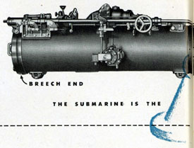
A submarine torpedo tube bears fairly close resemblance to a large naval gun. Its shape is somewhat
similar. It has a barrel with breech and muzzle.
As the gun fires a shell, the submerged torpedo tube
fires a torpedo, using compressed air rather than an
explosive for the purpose. One marked difference
between the torpedo tube and a gun, however, is
that the torpedo tube's projectile (the torpedo) is
self-propelling; the tube supplies only the initial
impetus or "start" for the torpedo.
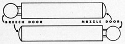
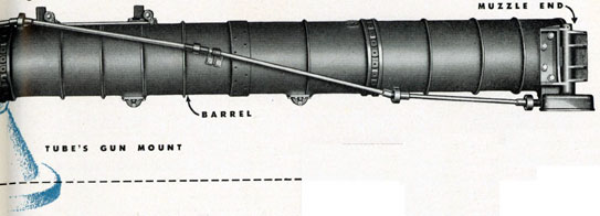
At each end of the torpedo tube, or barrel, is a
door-the breech door at the inboard end, the loading or operating end, inside the submarine; the
muzzle door at the outboard end, the firing or
ejecting end, opening out into the water. These
doors are operated, respectively, by the breech door
operating mechanism, and the muzzle door operating mechanism, both of which are located at the
breech end of the tube inside the submarine. All
operating mechanism, in fact, is located at and
operated from the breech end, the same as with a
gun. These mechanisms, which will be described
in following pages of this pamphlet, are interrelated
and interlocking.
With the muzzle door closed, the breech door is
opened, and the torpedo is loaded into the tube.
Before opening the breech door, however, the tube
must be drained of all water that entered the tube
during the preceding firing of a torpedo. For this
purpose, there is a system of drains and valves, all
operated from the breech end.
The firing mechanism, which sends the torpedo
out of the barrel and on its way to the target, includes an impulse tank charged from the submarine's high pressure air system, also a system of
valves, gages, etc.
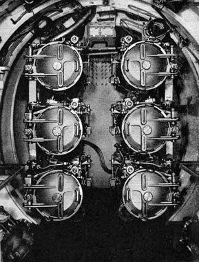
SS204 and 205 have four bow tubes and two stern
tubes. All other submarines numbered SS198 or
higher have six bow tubes (two vertical rows of
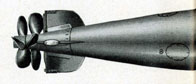
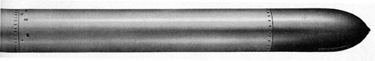
Figure 2 - The submarine torpedo tube's projectile is a torpedo.
10
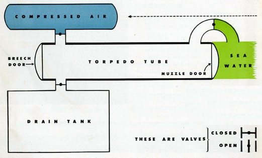
Figure 1-By means of compressed air the torpedo tube fires a self-propelling torpedo, giving it the initial impetus or start.
three each) and four stern tubes (two vertical rows
of two each).
Each of the integral parts of the torpedo tube,
and their operation, will be illustrated and described, in non-technical language so far as is possible, in the following chapters. Each torpedo is described in a separate pamphlet.
The chapters in this pamphlet should be studied
very carefully, so as to become familiar with all
parts and their relation one to another, and to the
ultimate purpose of the torpedo tube. There should
be no hesitancy about asking questions of those in
authority. When the time comes for going into
action against an enemy, there is no time to wonder
or to question about this or that part, or about what
should be done first and what next. Operation must
be, practically speaking, automatic. Orders must be
obeyed instantly. Therefore, assiduous application
to the study of this pamphlet is essential.
Figure 3-The breech end of a bow nest of 6 torpedo tubes.
11
GENERAL DESCRIPTION - PART 2
HOW A TORPEDO TUBE WORKS
Shown on these pages is a diagramatic explanation
of how a submarine torpedo tube works. The process
is greatly simplified here, and only basically resembles the actual operation. It is possible that a
simple torpedo tube might be constructed along
these lines that would actually fire a torpedo. All
that is intended in these diagrams and the accompanying description is to reduce the theory of the
torpedo tube to its barest fundamentals. With these
fully grasped, the refinements which cause the modern torpedo tube to function as it does will be more
easily understood.
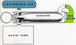
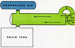
In the simplest form possible, a torpedo tube
would need to consist of no more than a barrel to
receive the torpedo, and the means of providing the
force necessary to discharge the torpedo from the
barrel. In this ease, the force is supplied by a tank
of compressed air which may be released into the
barrel by opening a valve.
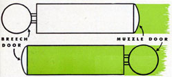
The breech of the barrel is fitted with a door
which serves the dual purpose of providing an opening into the tube, and blocking the escape of the
compressed air from the barrel by any other means
Figure 4
12
than forcing the torpedo ahead of it and out of the
muzzle. Since the muzzle is submerged in sea
water, it must also be fitted with a door to shut
Figure 5
out the sea while the breech door is opened to allow
the torpedo to be loaded into the tube. In this respect, the tube with its interlocked doors acts as an
air-lock (like an escape hatch).
A cardinal principle of submarine torpedo tube
construction is that one or the other of the tube's
two doors must always be closed, to prevent the
entrance of the sea into the submarine's interior. As
will be shown in following pages of this pamphlet,
interlocking devices are fitted to submarine tubes
to prevent the simultaneous opening of both breech
and muzzle doors. It scarcely seems necessary to
Figure 6
point out the suicidal folly of any attempt to defeat
the purpose of these interlocking devices.
With the muzzle door closed to prevent entrance
of the sea into the tube, its breech door is opened
and a torpedo loaded into it. The breech door is
then closed and the muzzle door may be opened.
It must be remembered, however, that at any
Figure 7
considerable depth below the sea's surface, there will
be water pressure against the muzzle door which
may be too great to be overcome by whatever force
is applied toward opening it.
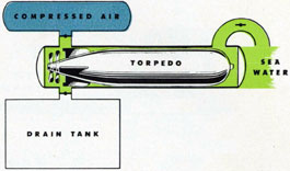
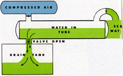
To offset this external pressure on the muzzle
door, an equal pressure is built up within the tube
by admitting water from a tank (simultaneously
venting the displaced air into the ship) and then
Figure 8
opening a valve which communicates with the sea.
With this done, no more force is required to open
the muzzle door than would be needed if the tube
and door were not submerged at all.
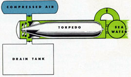
With the torpedo tube flooded with sea water at
the same pressure as that outside the muzzle door,
the door is opened and the tube is ready to fire the
torpedo. In actual practice, the tube is flooded from
13
tanks within the submarine rather than from the
sea itself; this avoids disturbing the trim or balance
of the vessel through increasing the weight of water
it carries.
Figure 9
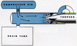
The tube now being ready to fire, a valve between
the compressed air supply and the tube is opened.
It is obvious that the air pressure must exceed the
sea pressure by sufficient margin to force the torpedo out of the tube. Here again, in actual practice,
the air charge is not permitted to completely fill the
tube and escape into the sea, but is vented off so as
to avoid causing a bubble of air to rise to the surface
and thereby betraying the submarine's location.
The torpedo having left the tube, the compressed
air is shut off, and the tube fills with sea water. This
tends to offset the lost weight of the torpedo, keeping the submarine in trim. In effect, this follows
actual practice. A submarine is held submerged on
level keel at any given depth by taking on or discharging carefully calculated amounts of water ballast. Failure to compensate for the weight of a heavy
torpedo can badly upset the vessel's equilibrium.
Figure 10
The torpedo tube having filled with water, the
muzzle door is closed, shutting out the sea. It is now
possible to open a valve leading to a drain tank,
and empty the tube, at the same time blowing in air
Figure 11
to replace the water, and to force it out faster. Thus
the weight of the water taken aboard to offset the
lost weight of the fired torpedo is retained in approximately the same locality. The breech door may,
after all the water is drained out of the tube, be
opened for reloading.