7A1. Equipment on submarines. The cooling
equipment of submarines consists of two separate systems, one for refrigeration proper, and
the other for air-conditioning. The refrigeration plant is described here. The air-conditioning plant is described in Chapters 13 to 20
inclusive.
7A2. The refrigeration plant. The capacity
of the refrigeration plant is one-half refrigeration ton when operating at 460 rpm with 5
gallons of water at 85 degrees F per minute circulating through the condenser, and a suction pressure corresponding to an evaporation temperature of -5 degrees F. The system consists of the
main elements connected to a circuit by
piping, with various valves, gages, and controls necessary for automatic operation. Each
item is described in detail later, with illustrations showing construction or operation. In
addition, Figure 7-1 shows the complete
refrigeration system, with all piping connections, and the location of all elements, valves,
and devices (this diagram is inserted at the
end of the book). The main elements and
accessories are as follows:
1. One compressor, York-Navy Freon 12,
enclosed single-acting vertical, two cylinders,
2 5/8-inch bore x 2 1/2-inch stroke.
2. One condenser, York-Navy Freon 12,
horizontal shell-and-tube 4-pass, 6 9/16 x 30
inches.
3. One receiver, York-Navy Freon 12, 6 x 36
inches.
4. One Kramer Trenton Model 71L ice cuber
in a Victor insulated cabinet.
5. One water cooler. This is not an integral
part of the refrigeration system. It consists
of a pipe leading out of the water storage tank
into the cool room where in a few coils it chills
the water before it goes out to the scuttlebutts.
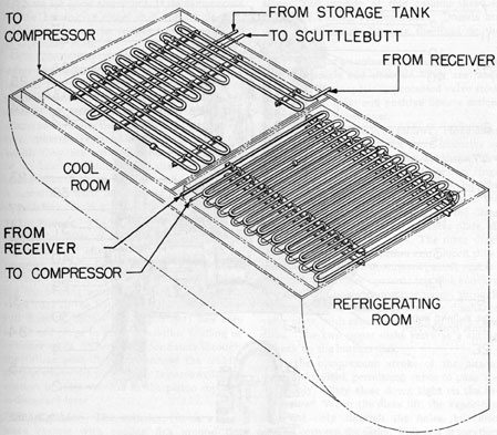
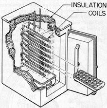
6. Two evaporators (see Figure 7-2). The
evaporators consist of the main refrigerant piping coiled back and forth on the overhead of
the insulated boxes to provide a large area of
cooling surface. One evaporator is in the cool
room and the other in the refrigeration room.
B. THE COMPRESSOR
7B1. General description. The compressor is
of the vertical, single-acting, reciprocating,
two-cylinder type.
1. Bore 2 5/8 inches; stroke, 2 1/2 inches.
2. Driven by three V-belts from a 1.75 hp
electric motor, speed 1750 rpm, 250 (175-345)
volts direct current (d.c.).
3. Lubricating oil charge, 5 pints of Navy
Symbol No. 2135, or equivalent.
4. The suction, or intake, valve of each cylinder is located in the piston top. The discharge
valves are located in the discharge valve plate
at the top of the cylinders. These valves are
of the flex-action diaphragm type and are easily
accessible. The tops and upper portion of the
sides of the cylinders are finned for air-cooling.
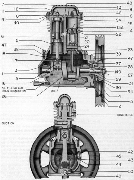
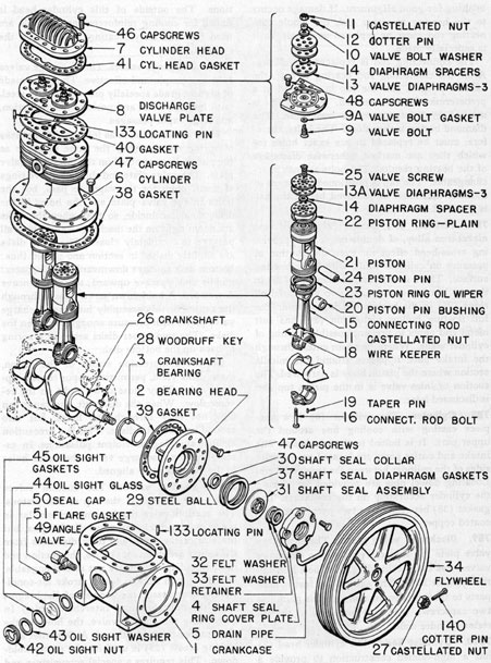
A sectional view of this compressor is shown
in Figure 7-3 and an exploded view in Figure
7-4. In the following description, numbers in
parentheses correspond to index numbers in
these figures.
7B2. Crankcase. The crankcase (1, Figures
7-3 and 7-4) is a single cast-iron case, designed
with smooth curved lines for strength and for
elimination of unequal stresses. It has a large
oil capacity to provide good lubrication and
ample heat dissipation. The crankcase opens
at only one end, for shaft removal, to keep the
points of possible leakage at a minimum. The
construction is especially rugged around the
bearing areas. A drain for removing oil and
a sight glass for checking the oil level in the
crankcase are provided.
7B3. Crankshaft. The crankshaft (26) is
made of die-forged open-hearth steel. It is
short, has great rigidity, and is so designed
that it needs no counterweights. The thrust
face on the dead end of the shaft is centrifugally
lubricated by oil that comes in through
holes bored in the shaft. Note that endwise
play of the crankshaft is controlled by the
thickness of the gasket (39) between the bearing head and the crankcase, at the power end
of the shaft. For repair, the entire crankshaft,
with rods and pistons attached, is removed and
replaced as a unit through the opening at the
top of the crankcase, after the cylinder casing
has been removed.
7B4. Crankshaft main bearings. The crank
shaft main bearings (3) are die-cast sleeve
type babbitt bearings, diamond bored to mirror
finish, with ample oil-ways for lubrication.
Note that these bearings are interchangeable.
The bearings are inserted by a light press fit,
and a lug on the bearing shell locks them, preventing rotation.
7B5. Bearing head to crankcase. The main
bearing at the drive, or flywheel, end of the
crankshaft is carried on a detachable bearing
head (2) bolted to the crankcase. The bearing
head may be removed by taking out the capscrews (47), after first removing the flywheel
(34) and shaft seal assembly (31).
7B6. Connecting rods. The connecting rods
(15) are made of malleable iron I-section, with
full-floating piston pins (24). The piston pin
bushings (20) are of bronze with oil holes. At
the crank pin end, the connecting rod bearings
are of centrifugally cast babbitt, diamond
bored to mirror finish simultaneously with the
29
Figure 7-3. Compressor, sectional view.
bushing for good alignment. If damage occurs
to the bearing at either end, the whole connecting rod must be replaced as a unit, as it
is especially made.
The connecting rod is replaced as follows
After the connecting rod bearing is cast, the
babbitt is split, and the cap is attached at a
predetermined bolt tension. Each bolt is
marked by reference to its own hole. The
diamond boring is then done. The bolts, Therefore, must be replaced in the exact holes for
which they are marked, otherwise distortion
of the bearing results. The bolts are not inter
changeable. The cap is positioned by means of
a dowel that must be removed before the cap
is detached.
7B7. Pistons. The pistons (21) are of cast
nickel-iron alloy, of double-trunk type providing cross-head effect for even distribution of
pressure on cylinder walls, with large bearing
surface. There is one compression ring (22) in
the top bearing section, and two ventilated oil
rings (23) in the bottom bearing section. The
full floating hollow piston pin (24) has soft
metal end plugs to prevent possible scuffing of
cylinder walls. When the vapor enters through
the intake port, it passes around the middle
section where the piston body is narrowed. The
suction or inlet valve is in the piston top and
is discussed later.
7B8. Cylinder. The cylinder (6) is a one
piece casting with cooling fins around the
upper part. It is bolted to the crankcase. The
intake and outlet ports are located on opposite
sides of the cylinder between the two cylinders.
Locating dowel pins are provided for placing
the cylinder accurately on the crankcase. The
gasket (38) between these two parts is of lead
coated copper.
7B9. Discharge valve plate. The discharge
valve plate (8) that carries the two discharge
valves, has holes coinciding with bolt holes in
the cylinder head. The same bolts fasten both
parts to the cylinder. In addition, this plate has
two capscrews (48) that attach it to the interior cylinder wall.
7B10. Cylinder head. The cylinder head (7)
has a high-domed construction to provide a
cushioning effect in reducing pressure pulsations.
The outside of this cylinder head is
finned for cooling reinforcement. Dowels are
used for accurately locating the head on the
cylinder.
7B11. Discharge valves. The discharge valves
(13) are simple and effective. They are, made
of highest grade specially processed valve steel,
with low lift, quiet and positive flexure action,
and large vapor passages.
Their construction is as follows: Three disks
of spring metal, nearly the same diameter as
the piston, lie assembled on the discharge valve
plate. The valve plate and the disks have rings
of small holes for the vapor to pass, but the
holes in the valve plate and the holes in the
disks do not coincide, so that when the disks
are down tight on the discharge valve plate, all
passage is completely closed. The three disks
are slightly dished in section and placed thus
bottom disk concave downward; small spacer;
middle disk concave upward; top disk concave
downward. A hold-down screw passes through
the center of this assembly into the discharge
valve plate, with pressure enough to flatten the
disks. The two upper disks serve as a spring
to back up the bottom disk.
On the compression stroke of the piston,
these disks yield, permitting vapor to pass up
ward only. They close down tight on the reverse flow. When the disks lift, the vapor can
flow not only through the holes, but also
around between the disks. This is a precaution
against slugging or violent pulsations. In assembling the discharge valve, the small holes
in the disks must be aligned.
7B2. Suction valves. The suction valves
(13A) are located at the top of the pistons.
The suction valve diaphragms are similar in
action to the discharge valve diaphragms, but
the size of the holes and their distances from
the center are different; hence, the suction and
discharge diaphragms are not interchangeable.
(In the 4-inch bore x 4-inch stroke air-conditioning compressor, the two sets of diaphragms
are alike and therefore interchangeable.) In
assembling the suction valve, the holes in the
diaphragms must be aligned. A Dardellet self
locking screw (25) is used for the center hold
down. This requires a special screwdriver and
valve hold-down bushing for installation.
31
Figure 7-4. Compressor, exploded view.
32
An additional safety feature is a small hole
through the side of the piston near the top.
When starting the compressor, this hole permits Freon 12 under excessive pressure to flow
through. In normal operation, at designated
pressure, this small hole is kept sealed by lubricating oil.
7B13. Gaskets. Lead-coated copper is used
for gaskets, and no special materials are required. However, at three points it is most
important that the correct specified thickness
be used. These points are:
1. Between discharge valve plate and cylinder. This gasket (40) determines the clearance between the piston top and the cylinder
head; this clearance is only a few thousandths
of an inch.
2. Between crankshaft main bearing head
and crankcase. This gasket (39) determines
the thrust collar clearance and the endwise
play of the shaft.
3. Between bearing head and shaft seal ring
cover plate. This gasket (37) controls the seal
tension diaphragm tension.
7B14. Crankshaft seal. The crankshaft seal
assembly (31) is the patented York Balanseal
construction, one of the salient features of the
York-Navy compressor, It has few parts and
no springs, and is easily serviced.
The seal between the shaft and the crankcase is made by the shaft seal collar (30).
Around the shaft and rotating with it, is a
fixed collar held in place by a steel ball (29),
the seal face of which is lapped to a fine finish.
Against the rotating seal face of this shaft
collar, another seal collar, or seal ring, presses.
This collar has a similarly lapped face and is
held stationary by a spring diaphragm attached to the crankcase. The diaphragm is
under tension in the assembly and holds the
two sealing faces together at a definite pressure.
The construction, operation, and adjustment of this seal are described in Sections
10K1 to 10K7.
Seals are designed for either clockwise or
counterclockwise operation and are not inter
changeable. Submarine installations are counterclockwise seals.
The rubbing faces of the two seal collars
are lubricated by means of small holes in the
seal face, carrying oil across the contact surfaces. This seal is below the oil level in the
crankcase and oil flows by gravity into the
seal from the shaft bearing. Therefore, a
slight seepage of oil always appears on the
outside of the seal.
7B15. Lubrication. The main shaft bearings
and seal are flooded. The thrust bearings, receive a constant stream of oil from the centriforce oiler. The piston pin bearings and cylinder walls are lubricated by the usual
splash-vapor method. The seal collar face is
kept oiled by the rotation of the shaft. A
number of pin-point depressions are arranged
in a spiral path on the seal collar face, and oil
working into these depressions provides uniform lubrication across the face.
7B6. Miscibility of oil and Freon 12 vapor.
Freon 12 mixes readily with oil. However, no
chemical reaction takes place, so that no harm
is done to either. This mixing has a definite
pressure-temperature relationship. For example, with an oil temperature of 60 degrees F and
a pressure of 40 pounds gage, DTE heavy
medium oil absorbs Freon 12 vapor to about
60 percent by weight.
The absorption increases with elevation in
pressure, lowering of temperature, and length
of compressor shutdown. Therefore, if there is
a long shutdown, the oil absorbs so much
Freon 12 that a high oil level appears in the
sight glass. Actually the amount of oil may be
below normal.
CAUTION. It is possible that even after
a prolonged shutdown this oil and Freon 12
mixture may fill the crankcase. If the compressor is started under such conditions,
damage to some part or parts is probable.
Even if the oil-Freon 12 mixture does not fill
the crankcase, starting may cause a sudden
lowering of pressure in the crankcase, producing a violent boiling and foaming of the
oil as the Freon 12 vapor leaves. This in turn
would result in a loss of oil from the crankcase. Special care should be taken to check
this matter after any shutdown. Moreover,
gathering of frost on the crankcase indicates
33
a lowering of temperature within, caused by
too low pressure or some other possible cause,
in which case the same troubles might arise.
Frost should not be permitted to form on the
compressor crankcase, and in the event that
it does, the system should be checked immediately.
NOTE. Because of the ready mixing of oil
and Freon 12, oil must never be used in testing for Freon 12 leaks (see also Section 11F3).
C. CONDENSER AND PUMP
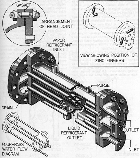
7C1. The condenser. The condenser is a four-pass water-cooled condenser of conventional
shell-and-tube construction. The shell is made
of brass, 30 inches long and 6 9/16 inches in
diameter (see Figure 7-5). The condensing
water enters and leaves at the same end in
four sets of six tubes each, the tube ends being
belled for better entrance. The heads are semispherical with baffle-plates cast enbloc to return the water flow. The water enters the
lower-left set of tubes, returns through the lower-right set, goes back again through the
upper-right set, and flows out finally through
the upper-left set. The Freon 12 vapor enters
the condenser shell at the top, flows around
these water tubes, condenses, and drips to the
bottom where the liquid Freon 12 exists.
Vents and drains are provided.
The condenser is of such size that when the
refrigerating system is operating at -5 degrees F
evaporation temperature and is supplied with
10 gallons per minute of 85 degrees F water, for each
refrigeration ton, the head pressure does not
exceed 125 pounds gage. The condensing
water enters at 85 degrees F and leaves at 88 degrees F, with
a velocity of 73.5 feet per minute through
tubes. The flow of water through the condenser should be controlled by regulating the
opening of the discharge valve on the condenser. The desired temperature can be maintained by controlling the flow of water through
the condenser. If water at too low a temperature is allowed to flow through the condenser,
it may be impossible to maintain the desired
discharge pressure of the refrigerant at the
compressor.
Never attempt to control the flow of water
or regulate the temperature of the water
through the condenser by the inlet valve. The
inlet valve should be kept fully open at all
times. The water side of the condenser is
tested to 236 psi. Therefore, the suction to sea,
through which cooling water is supplied to
the condenser, can be left open until the
vessel submerges to a depth at which sea pressure is greater than the test pressure of the
water side of the condenser. This depth is
approximately 500 feet.
It is good practice to secure the plant and
sea valves when submerging below 300 feet or
when expecting a depth charge attack, and to
open the vent on the water side of the condenser. This aids in preventing damage to the
condenser during depth charging. At both
ends of the condenser, two zinc fingers, or
rods, extend into the water side. They are
screwed in securely from the outside so that
they may be removed easily and inspected
without having to remove the heads. These
zinc fingers act as protectors, that is, they tend
to protect the other metal parts from the corrosive action of the water caused by electrolytic action induced by stray electric currents
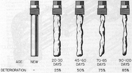
in the metal parts. These zinc fingers should
be inspected at least once a month and replaced
when deterioration reaches 50 percent.
A zinc finger when new and at four stages
of increasing deterioration is illustrated in
Figure 7-6.
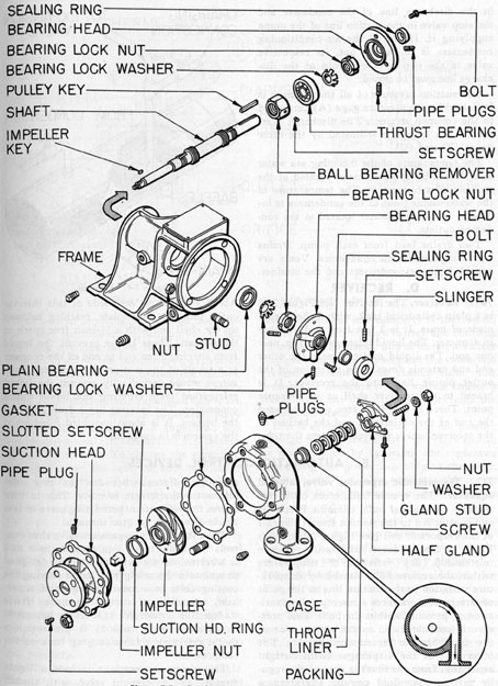
7C2. Condenser water pump. The cooling
water that condenses the Freon 12 vapor is
supplied by a volute type of centrifugal pump.
In the centrifugal pump, the intake water
enters into the center, of the impeller on the
axis of the pump. This impeller is carried on
a shaft, both bearings of which are on one
side, opposite the inlet. The impeller lies in
a plane perpendicular to the axis. An exploded view of the pump is shown in Figure
7-7.
The impeller is of the enclosed type, that is,
the water flows in passages inside the impeller
(see Figure 7-7). The shaft is directly connected to a motor and turns at high speed.
This speed imposes a centrifugal force on the
water in the impeller passages. This centrifugal force causes the water to flow at high
velocity from the eye, or inlet, of the impeller
34
outward toward the periphery. This outward
flow under centrifugal force creates a "suction"
at the eye which pulls the feed water into the
pump.
The inner surface of the case that surrounds
the impeller has a volute, or spiral-shaped section, that is, an increasing radius around the
circumference. The small inset in Figure 7-7
shows a sectional view of the case and volute
interior. The volute case is designed to produce an even flow of water around the periphery and to reduce the velocity of flow gradually
as the water flows from the impeller to the
discharge outlet of the pump. This reduction
Figure 7-5. Condenser.
35
in velocity changes the velocity head into
pressure head.
The advantages of the centrifugal type pump
are: 1) the flow from it is continuous; 2) the
flow can be throttled without building up an
excessive pressure, or overloading the motor;
and 3) it operates at speeds normal to an electric motor; hence, it may be directly connected.
In the refrigeration system, one pump is
used. It runs normally at 3,500 rpm, with a
discharge pressure of 25 psi, and has a capacity
of 5 gallons per minute (gpm).
In the air-conditioning system, two pumps
are used, one for each condenser. Each pump
runs normally at 2,600 rpm, with a discharge
pressure of 25 psi, and a capacity of 40 gpm.
7C3. Circulating water systems.Figure 7-8
(inserted as a foldout at the back of the book)
is a diagram of the circulating water supplying the condensers of the refrigeration and
air-conditioning systems.
One pump supplies 5 gpm of cooling water
at 25 psi discharge pressure to the refrigerating condenser. Two pumps, one for each condenser, supply 40 gpm of cooling water at 25
psi discharge pressure to the two air-conditioning condensers. All three pumps take
their suction from the same sea chest and
strainer through pipes (1) and (2). In pipe
(2) a hose valve (10) is connected for emergency water feed to the system through the
inlet side of the strainer. This connection
normally is used to supply water to the system while the vessel is in dry dock.
Two separate suction lines lead from the
basket-type strainer: pipe (3) supplying the
refrigerating condenser pump and pipe (6)
supplying the two air-conditioning condenser
pumps. All pipes to the three pumps are provided with stop valves so that any one of the
pumps may be shut off without halting the
operation of the others.
The discharge from the refrigeration condenser pump goes directly to the condenser
through pipe (4). From the refrigeration condenser, the circulating water goes through
pipe (5) to a connection into the overboard
discharge pipe (9).
The discharge from the two air-conditioning condenser pumps goes directly through
pipes (7) to the two condensers. From the
air-conditioning condensers, the circulating
water goes through pipes (8) to a common
two-valve manifold, and then into the overboard discharge pipe (9).
Any of the condensers may be cut out for
cleaning or repair by closing the stop valve
Figure 7-6. Zinc fingers for condenser, showing stages of deterioration.
36
Figure 7-7. Condenser water pump, exploded view.
37
in the discharge line of the condenser and
the stop valve in the suction, line of the pump
supplying it. If one of the air-conditioning
condensers is to be cut out, its respective
valve in the two-valve manifold of the discharge line must be closed.
The suction pressure of all three pumps is
indicated by the pressure gage (A) connected
to the common strainer. The discharge pressure of the pumps is indicated by the three
gages (B) and (C).
The temperature of the incoming sea water
is indicated by a thermometer located at the
strainer inlet connection. The temperature of
the water coming out of the condensers is indicated by a thermometer located at the condenser outlets.
Two drains lead from each pump. Drains
also are provided on condensers. Vents are
provided on the condensers and the strainer.
D. RECEIVER
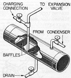
7D1. Receiver. The receiver (see Figure 7-9)
is a plain cylindrical tank, with dished heads
made of brass. It is 3 feet long and 6 inches
in diameter. The liquid inlet is at the top, near
one end. The liquid outlet is near the other
end and extends down as an extension of the
outlet piping line into the receiver. It is
brazed to the receiver shell at its entrance
point. There is a 1/2-inch free space between
the end of the outlet tube and the bottom of
the receiver, where the liquid enters the tube.
Figure 7-9. Receiver.
About 3 inches on each side of this interior
outlet tube is a baffle-plate, reaching halfway
up the shell and with a 1/2-inch free space at
the bottom. These baffles prevent the liquid
from surging from end to end of the receiver
as a result of the motion of the vessel. Such
surges would periodically prevent the liquid
refrigerant from entering the liquid outlet
connection. The receiver has a drain valve in
the bottom. It is about one-third filled when
the system is in operation.
E. AUTOMATIC CONTROL DEVICES
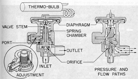
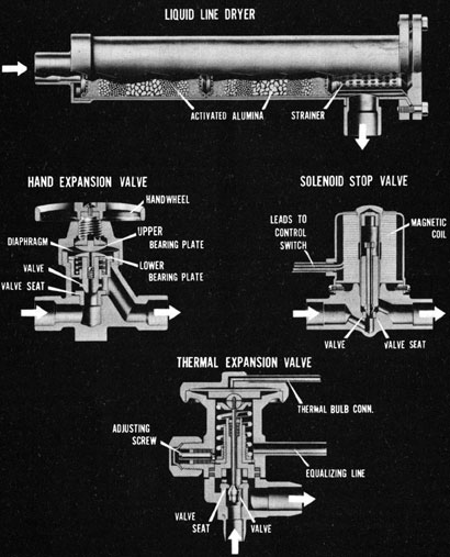
7E1. Thermostatic expansion valve, internal
equalizer. The remote bulb, often called the
thermo-, or thermal bulb, contains Freon 12,
and is attached to the suction line at the exit
of the evaporator coil (see Figure 7-10). Since
Freon 12 has an exact temperature-pressure
relationship, any variation of temperature
within the remote bulb, caused by temperature variation in the suction line at the point
of attachment, produces a corresponding variation of pressure within the bulb. This pressure is communicated to the upper side of
the diaphragm in the expansion valve. The
other side of the diaphragm (with airtight
separation from the first) is part of the regular refrigeration fluid circuit. Therefore, a
pressure difference between the two sides
causes the diaphragm to move. This in turn
moves the valve stem, permitting more or less
liquid Freon 12 to flow through.
The thermostatic expansion valve thus controls the quantity of liquid refrigerant that
is admitted to the evaporator. It is designed
to maintain the refrigerant vapor leaving the
cooling coils at a constant degree of super
heat, regardless of suction pressure. Hence
its function is twofold: 1) it acts as automatic
expansion control, and 2) it prevents the
liquid refrigerant from surging back to the
compressor.
The piping connections include a liquid
strainer and a solenoid valve, with shutoff
valves used in servicing the strainer, solenoid
valve, and thermostatic expansion valve; and
manually operated valves for use if it is desired to examine the thermostatic expansion
valve or solenoid valve, or to clean the strainer.
a. Adjusting the thermostatic expansion
valve. Some thermostatic expansion valves are
set in the factory at 5 degrees F superheat. Navy
specifications call for 10 degrees F superheat, and
expansion valves for submarines are factory
set at this amount. To change the superheat
setting, remove the seal nut and manipulate
the adjusting stem. Turning this stem clock
wise (tightening the spring) increases the
superheat and reduces the flow of liquid
through the valves. Turning the stem counter
clockwise reduces the superheat and increases
the flow through the valve. After this final
setting, it is seldom necessary to readjust it.
These valves are made to control accurately
the amount of superheat in the suction vapor.
They will not withstand rough usage; After
they are once adjusted, they must not be
played with or readjusted, unless there is
distinct evidence that they are not functioning properly.
b. Thermostatic expansion valve trouble.
The thermostatic expansion valve should
function without any difficulty if the system
is free of dirt or foreign matter and contains
no moisture. However, dirt or foreign matter
may get in between the seat and the valve, and
prevent the valve from closing tight. The
presence of moisture in the system causes a
freeze-up at the valve port and prevents the
passage of Freon 12.
If it is evident that Freon 12 is not passing
through the expansion valve, the valve should
be disassembled by removing the capscrews
connecting the power assembly to the body.
This permits the valve cage assembly to be
examined for the presence of such things as
frost, ice, or dirt.
Care should be taken in reassembling the
thermostatic expansion valve to see that all
gaskets are properly placed, and that the
valve cage assembly is properly aligned.
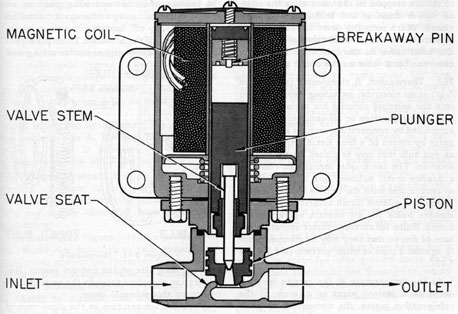
7E2. Solenoid valve. The solenoid valve (see
Figure 7-11) is an important control device
in the system, since it is the valve that halts
the operation automatically in response to
operating conditions. It is located in the
liquid refrigerant line ahead of the thermostatic expansion valve. When the current is
on, the magnetic coil of the valve is energized,
causing the plunger to retract and lift the
39
NavPers 17130, E-40, E-135
Figure 7-10a. Typical refrigeration control devices.
valve off its seat, thus permitting the refrigerant to flow through. When the space that the
thermostat controls reaches the desired temperature, the thermostatic control device
breaks the electrical circuit, and the magnetic
coil releases the plunger, instantly closing
the valve and completely stopping the flow
of refrigerant.
A breakaway pin under spring pressure acts
as a kickoff when the electrical circuit is interrupted, assuring positive closing of the
valve.
The valve-closing part is a small piston,
separate from the valve stem. This piston has
a loose fit, so that when it is closed, the high-pressure liquid may flow up between it and
the body wall, exerting this pressure downward on the piston top to maintain a complete
and tight closure.
The valve stem also is separate from the
plunger. When the magnetic coil is energized,
the plunger snaps up, striking a hammer blow
against the upper flange of the stem to insure
positive opening. The stem, thus lifted off
the secondary seat in the piston, enables the
high pressure above the piston to flow out
through the piston opening. Since the closing
pressure on the piston is thus removed, the
incoming liquid flow causes the piston to rise,
fully opening the valve.
The magnetic coil is extra powerful and
does not need Fusetron protection on alternating current. A surge protector is included
for direct current in excess of 50 volts. The
coil does not overheat or burn out under normal service.
The coil and leads are waterproof, which
prevents failure caused by condensation of
moisture in low-temperature or high-humidity
compartments.
The solenoid valve should be located in a
horizontal line, with the direction of refrigerant flow corresponding to the arrow on the
valve body, and the coil in a vertical lane
above the valve.
Liquid Freon 12 should never be permitted
Figure 7-11. Solenoid valve.
41
Figure 7-12. Thermostat.
to remain trapped in the valve after the shut
off valves ahead of and behind it have been closed. When pumping down for examination
or removal of the solenoid valve, always close
the hand valve on the inlet side first; later
close the hand valve on the outlet side.
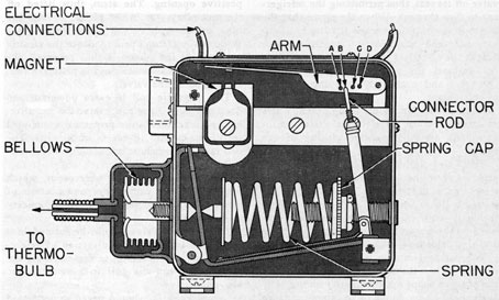
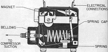
7E3. Thermostat. A thermostat (see Figure
7-12) is an electrical switching device (wired
into the solenoid circuit) for automatic control of refrigeration or air-conditioning. It is
controlled by temperature changes at a remote
point by means of a long flexible tubing with
an end bulb that may be placed at any desired
location. The thermostat mechanism contains
a flexible metal bellows, one side of which
communicates with the remote bulb tubing in
which is a volatile liquid similar to Freon 12.
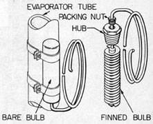
Remote bulbs for air contact operation are
finned. Bulbs for surface contact operation are
bare of fins so that they may be clamped firmly against a pipe or other surface (see Figure
7-13).
As the temperature at the remote location
drops to a desired point as a result of the
refrigeration action, the corresponding pressure of the liquid within the tubing moves
the bellows to degrees (its set operating position, so
that it causes a spring-and-magnet-controlled
contact to snap off, breaking the electric circuit and closing the solenoid. The snap action
is rapid, thus preventing excessive arcing and
Figure 7-13. Thermo-bulbs.
insuring long life of the contact points. Refrigeration therefore stops in the section controlled by this solenoid valve.
When the temperature at the same remote
location rises above the desired point, the
42
reverse action takes place. The switch snaps
on, closing the electric circuit, thus opening
the solenoid valve and starting refrigeration
again. By this means, the refrigeration is
maintained economically at a desired temperature. When all solenoid valves are closed, the
compressor is stopped by the low-pressure
cutout switch.
On some installations, the thermostats used
on the refrigerating boxes have two contact
points. One contact point controls the solenoid valve on the meat or vegetable room, and
the other is connected to the solenoid valve
on the ice cuber. The ice cuber does not have
a thermostat, and the solenoid is wired in
parallel with the meat and vegetable room
thermostats. If the contact points on either
the meat or vegetable room thermostats are
closed, the ice cuber solenoid valve is open.
a. Temperature adjustment. To dower the
temperature at which the thermostat breaks
the circuit, causing the solenoid valve to
close, turn the spring cap (see Figure 7-12)
counterclockwise. This decreases the tension
on the spring. To raise the temperature at
which the thermostat breaks the circuit, turn
the spring cap clockwise.
b. Differential adjustment. The thermostat
cannot, of course, keep the temperature at one
absolutely exact degree. It keeps it within a
certain limited range of temperatures. The
range is called a differential. The holes (A, B,
C, and D in Figure 7-12) in the arm permit
variation of the differential. Minimum differential is secured by attaching the connector
rod hook in hole A. Moving the hook to the
holes B, C, or D increases the differential
by approximately 20 degrees F for each hole.
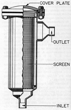
7E4. Liquid strainer. Because of the solvent
quality of Freon 12, any particles of grit,
scale, and so forth that the system may contain are readily dislodged from the piping
and fittings.
Strainers (see Figure 7-14) are provided in
the liquid line branches to each evaporating
surface, to protect the thermostatic expansion
valve and the solenoid valve. If a liquid line
strainer becomes clogged to the extent that
it should be cleaned, this condition is evidenced by a loss of refrigerating effect in the
room or surface on the line that it protects.
The liquid strainer can be tested by placing
the hand alternately on the strainer and on
its inlet line. If the strainer feels distinctly
colder than the line, it is a sign of partial
clogging and the screen probably needs to be
cleaned. All pressures should be checked. If
frost gathers on the strainer shell, it is a sign
of bad clogging, and the screen should be
cleaned immediately.
To clean a liquid line strainer, shut off the
manually operated stop valves ahead of and
behind it and open the manual bypass valve a
slight amount in order not to interrupt refrigeration. Loosen the cap, or cover plate,
which is bolted to one end of the liquid strainer and remove the internal screen. Dip the
screen in an approved cleansing solvent and
blow it out with air. Also blow out the inside
of the strainer body with air.
IMPORTANT. When placing the strainer
back in the line, blow a little Freon 12 vapor
through it to remove the air before closing
the cover plate joint.
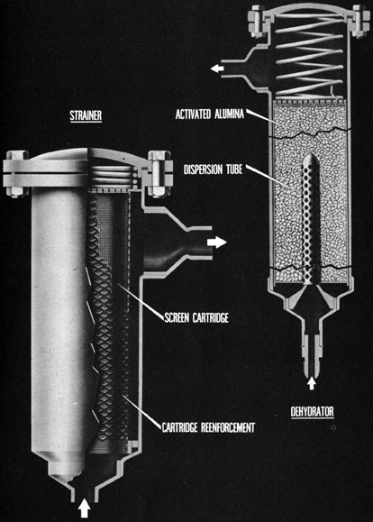
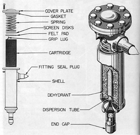
7E5. Dehydrator. A dehydrator (see Figure
7-15) is inserted in the liquid line between
the receiver and the evaporator. The piping
connection includes a three-valve bypass, so
that it can be isolated when not in use.
The dehydrator is intended to be used only
in charging the system with Freon 12, when
adding refrigerant to compensate for loss
through leaks, or when the presence of moisture in the system is suspected, as would be
evidenced, for example, by a freeze-up at one
of the expansion valves.
The dehydrator drying element is a cartridge filled with activated alumina or silica
gel, which absorbs any moisture in the liquid
refrigerant that is passed through it.
There is no definite rule governing the
length of time that the drier charge remains
effective, but it is generally considered advisable to renew or reactivate it after it has been
used for 12 to 15 hours.
After the dehydrator has been in use for a
while, its cartridge also gathers some sediment, thus restricting the passage of liquid
through it. If the outlet end of the dehydrator
shell feels cold to the hand, this indicates
partial clogging. If this coldness increases,
the cartridge should be replaced. If frost
43
gathers on the shell, it is a sign of bad clogging and the cartridge should be replaced at
once.
Reactivation of a used cartridge is accomplished by subjecting it to heat (300 degrees F) in a
ventilated oven for 12 hours; then sealing the
ends of the cartridge, and allowing it to cool.
IMPORTANT. After placing the cartridge
back in the shell, blow a little Freon 12 vapor
through it from the inlet side, to free the shell
of air; then tighten the end cap.
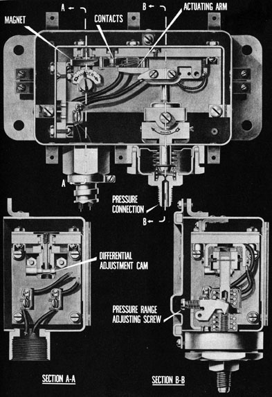
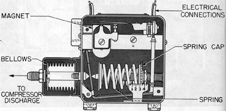
7E6. Low-pressure cutout. The low-pressure
cutout and high-pressure cutout switches are
similar in mechanism to the thermostat.
The low-pressure cutout, or suction pressure, switch (see Figure 7-17) is located on the
compressor base or on a panel adjacent to it.
The tubing leading to its bellows is connected
into the suction line at the intake port. Its
wiring is connected into the pilot circuit of
the compressor motor starter. When all the
solenoid valves have closed, thus halting the
refrigerant flow, the suction pressure drops
until it reaches the setting of the low-pressure
cutout, which is about 2 psi. When the suction pressure reaches this point, the switch
opens, thus stopping the compressor.
If, for any other reason, the pressure in the
low-pressure line should drop, the cutout
switch stops the compressor at 2 psi. When
one or more of the solenoid valves open, the
suction pressure will rise, causing the switch
to close and start the compressor. This switch
has a differential of about 18 psi. That is, it
stops the compressor when the low pressure
drops to 2 psi, and snaps on at about 20 psi,
restarting the compressor. The low-pressure
cutout provides automatic control of the system. It halts the system when the desired
degree of coolness in all spaces has been
reached, thus making possible economical
operation, and it prevents the rooms from getting too cold.
a. Pressure adjustment. To raise the low-pressure cutout point, turn the spring cap to
increase the compression of the spring. To
lower the low-pressure cutout point, turn the
spring cap to decrease the compression of the
spring.
In some cases it may be desirable to increase
the differential between the cutin and cutout
points to prevent short cycling of the compressor.
Where solenoid valves controlled by thermostats are used in multiple evaporator installations, set the suction pressure switch to stop
the compressor after the last solenoid valve
has closed, and to start the compressor again
when one or more of the solenoid valves have
opened.
7E7. High-pressure cutout. The high-pressure cutout switch (see Figure 7-18) also is
located on the compressor base or on a panel
adjacent to it. The tubing leading to its bet
lows is connected to the high-pressure line at
the discharge port. Its wiring is connected
to the pilot circuit of the compressor motor
starter. This switch serves as a safety device
to prevent dangerously high pressure from
developing within the system. When the discharge pressure rises to the setting of this
Figure 7-14. Liquid strainer.
44
NavPers 17022, Amphib 104
Figure 7-14a. Dehydrator and liquid trainer, York ice machine.
45
switch, which is usually 150 psi, the switch
opens, stopping the compressor and shutting
down the system. This switch has a differential of about 25 psi. When the high pressure
falls to 125 psi, the switch closes, automatically starting the compressor again.
a. Pressure adjustment. To raise the high-pressure cutout point, turn the spring cap to
increase the compression of the spring. To
lower the high-pressure cutout point, turn the
spring cap to decrease the tension of the
spring.
7E8. Relief valve. The relief valve is of the
conventional positive self-seating type, located on the discharge line from the compressor. It is furnished with interconnecting
piping, and serves to vent excessively high
discharge pressure to the suction, or low-pressure, side of the compressor. The relief
valve acts as a safety device, and in the event
that the high-pressure cutout switch should
fail to stop the compressor, it comes into
operation at 200 psi, preventing any further
rise in pressure and bypassing this back to the
low-pressure side.
Figure 7-15. Dehydrator.
46
NavPers 17022, Amphib 106
Figure 7-16. Low- and high-pressure control switch, York ice machine.
47
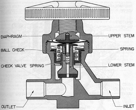
7E9. Packless valves. A number of packless
stop valves (two-way and angle types) are
inserted in the refrigerating circuit at various
places. A two-way valve is illustrated in Figure 7-19. This type is of the packless design
and contains a puncture- and blowout-proof
diaphragm that seals off the fluid flow chamber from the outside handle stem space. The
lower stem is separate and is kept in contact
with the upper stem, or handle part, by a
spring; the sealing diaphragm is located between the two parts.
The combination bypass and check valve
incorporated in the lower stem provides automatic opening under any pressure regardless
of spring tension or spring size. This feature
eliminates the necessity of applying pressure
on the lower end of the stem seat and consequently makes this valve a multidirection
universal packless valve.
Figure 7-17. Low-pressure cutout switch.
Figure 7-18. High-pressure cutout switch.
48
Figure 7-19. Packlass valve.
Figure 7-20. Type Q Navy manifold, exterior.
49
Figure 7-21. Type Q Navy manifold, cutaway.
50
In the closed position of the valve, the diaphragm and the check valve seal the bypass
and prevent leakage to the auxiliary valve
chamber. In the open position of the valve,
the check valve seals the bypass, with a positive metal-to-metal back seat, and permits the
removal of the diaphragms for inspection or
replacement under full pressure.
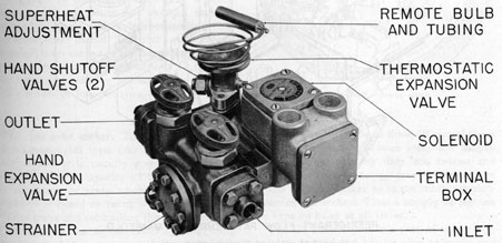
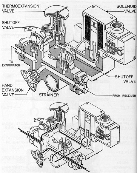
7E10. Type Q Navy manifold. The Type Q
Navy manifold (see Figure 7-20) is a new
development in which several of the separate
control valves are contained in a single compact casing. These include the thermostatic
expansion valve, solenoid, strainer, hand expansion valve, shutoff valves, and flanged line
connections. Taking the place of assemblies
of the separate items, it eliminates 20 joints,
which are always potential refrigerant leakage points.
There are two types of Type Q Navy manifolds, one with an internal equalizer on the
expansion valve for the refrigeration system,
the other with an external equalizer on the
expansion valve for the air-conditioning system. Figure 7-21 shows cutaway views of interior construction and flow path through the
manifold.
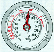
7E11. Gages and thermometers. The refrigeration system also includes the necessary
pressure gages and thermometers for observing the pressures and temperatures at various
places in the circuit.
Figure 7-22 illustrates the dial of a Freon
12 gage. The pressure and vacuum scale is
printed in black, and the corresponding temperature scale in red. The short pointer, red
in color, is an extra nonworking, or stationary,
pointer that may be set manually to indicate
the maximum working pressure. The gage for
the suction, or low-pressure, side reads to 150
psi. The gage for the discharge, or high-pressure, side (and the separate testing gage)
reads to 300 psi. Both read to 30 inches of
vacuum.
NOTE. The temperature scale on this gage
indicates temperatures of Freon 12 corresponding only to the pressures measured. The
gage cannot measure temperatures directly.
7E12. Suction strainer. The suction vapor
strainer is similar to the liquid strainer and
is located near the compressor, connected to
the suction inlet line. Its purpose is to prevent scale, dirt, or foreign matter from entering the compressor, where they might injure
the finely finished surfaces of the valves or
cylinder walls. The strainer body can be
opened by unbolting its cap and the strainer
screen can be removed for cleaning (see Section 9F1 for directions on care and cleaning).
Figure 7-22. Freon Gage.
F. ACCESSORIES
7F1. Ice cube maker. The ice cube maker is
of a commercial type (see Figure 7-23). On
submarines it is usually a seven-tray cuber,
and has a rated capacity of 15 pounds of ice
in six hours or sixty pounds per day. This
capacity is based on using water at 100 degrees F to
fill the trays and subcooling the ice 15 degrees.
The capacity can be increased by staggering
the filling of the trays, that is, instead of filling
all seven trays at one time, fill two of them
at a time at about one-hour intervals. Empty
the trays as soon as they are frozen and
put the ice in the storage tray in the bottom
of the ice cube maker or in the meat compartment of the icebox. Thus a supply of ice can
be kept on hand at all times.
The ice cube maker is a part of the refrigerating system and has its own solenoid and
51
expansion valve (see Figure 7-1). The solenoid valve is wired into the electrical circuits
of the solenoid valves of the cool room and
refrigerating room in such a way that if either
one of these two solenoid valves remains energized, the ice cube solenoid valve also remains
energized. If both of these solenoid valves
shut down, halting the refrigeration system,
the ice cuber also stops operation.
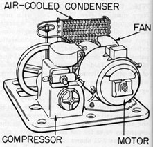
7E2. Wardroom refrigerator. The wardroom
refrigerator is designed especially for submarine
Figure 7-23. Ice cube maker.
installation and is built into the vessel.
The refrigerating unit is located to the left
of the box under the sink. The outstanding
feature of this machine is that the condenser
is air-cooled (see Figure 7-24). The refrigerator is for daily preservation of food used in
the wardroom.
Figure 7-24. Wardroom refrigerator unit.
7F3. Scuttlebutt. A water coil in the cool
room supplies cold water for the wardroom
scuttlebutt. Care should be taken to keep the
temperature of the cool room above freezing
in order not to freeze the water in the coil.