6A1. Main elements in the cycle. In Section
4A1, a brief statement of the principles of
mechanical refrigeration was given. In this
section, a detailed explanation of the full
cycle of operations is presented.
In the circuit of mechanisms through which
the refrigerant Freon 12 flows, there are five
main elements. Starting from the point where
we wish to remove heat, they are: 1) evaporator, 2) compressor, 3) condenser, 4) liquid receiver, and 5) expansion valve. In addition,
various control and safety devices are connected into the circuit.
6A2. The heat pump. The refrigerant cycle
is more easily understood when it is compared
to the flow of water. Everyone knows that
water naturally flows downhill that is, it
always flows from a higher level to a lower
level under the pull of gravity. If it is necessary to raise water from a lower level to a
higher one, it must be either carried up or
pumped up through a pipe. In either case,
work is done on the water, or in other words,
energy is used. In the same way, heat always
flows naturally from a region of higher temperature to a region of lower temperature.
If the desire is to move heat from a region of
lower temperature to a region of higher temperature, it is necessary to do work on it-to
use energy. Therefore, the compressor in the
cycle might be called a heat pump by means
of which heat is pumped up-thermometer.
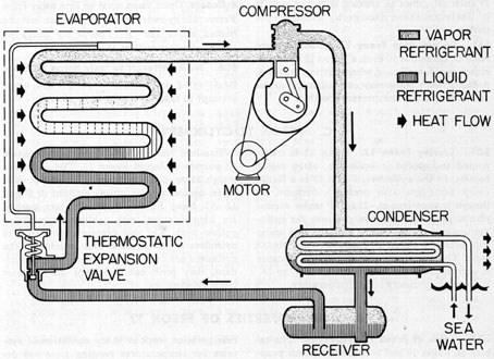
Figure 6-1. Mechanical refrigeration cycle.
22
In mechanical refrigeration, the compressor
is, in effect a heat pump. In the compressor,
work is done on the refrigerant by means of
an electric motor which turns the compressor
shaft, making the pistons move back and forth
in the cylinders, The pistons compress the
low-pressure vapor entering the cylinders to a
high-pressure vapor.
Since, according to the law of conservation
of energy, energy cannot be destroyed but
can only be altered in form, it must appear
somewhere. The input of energy has come
through the electric motor by means of the
crankshaft and pistons, and by their motion
it is transferred to the vapor by increase in
pressure. In that vapor, the input energy can
appear only in the form of heat, which results
in a rise in the temperature of the vapor.
6A3. The Freon 12 cycle. Let us follow
through the cycle of operation, starting from
the point where the heat to be removed enters
the refrigerating system. This point is the
location of the evaporator. Figure 6-1 is a
highly simplified diagram of the main mechanical elements in the cycle.
6A4. Through the evaporator. The evaporator is simply a bank, or coil, of copper tubing.
It is filled with Freon 12 at low pressure and
temperature. Heat flowing from the air spaces
or articles to be cooled into the coil causes
the liquid Freon 12 to boil. Boiling can take
place only as a result of the entrance into the
liquid of its latent heat of vaporization, and
this latent heat can come only from the surrounding substances. Hence the temperatures
of the surrounding substances are lowered.
The latter portion of the evaporator coil is
therefore filled with Freon 12 vapor at low-pressure, carrying with it the unwanted heat.
6A5. Through the compressor. This vapor
does not remain in the evaporator. The compressor is operating and the suction which it
exerts (on the evaporator side of its circuit)
pulls the heat-laden vapor out of the evaporator, through the piping, and into the compressor. The compressor, therefore, is the
mechanism that keeps the Freon 12 in circulation through the system. In the compressor
cylinders, the Freon 12 is compressed from a
low-pressure vapor to a high-pressure vapor,
and its temperature therefore rises, as explained in Section 6A2.
6A6. Through the condenser. The freon
vapor, now at high pressure, passes next into
the condenser, where the vapor passes around
the tubes through which sea water is continuously pumped. Here the excess heat flows by
conduction through the walls of the tubing
from the higher temperature vapor to the
relatively lower temperature sea water, and
here the unwanted heat leaves the primary
refrigerating system and is finally carried
away. The excess heat thus flowing out of the
vapor is both superheat and latent heat of
vaporization, and therefore the vapor condenses back to the liquid state. The liquid
Freon 12 is now at high pressure and high
temperature.
6A7. Through the receiver. The liquid Freon
12 goes now into the receiver, or tank. The
liquid in this receiver acts as a seal between
the vapor in the condenser and the liquid as
it flows into the next element, the expansion
valve, so that the liquid Freon 12 in the expansion valve may be free of vapor. Remember
that the whole system is a single circuit in
which the fluid flows around and around.
6A8. Through the expansion valve. The liquid
Freon 12 enters the expansion valve at high-pressure and high temperature. This valve
regulates the flow of the refrigerant into the
evaporator. The liquid outlet from this expansion valve is a small opening called the orifice.
In passing through the orifice, the liquid is
subjected to a throttling action, and there is
dispersed into a finely divided form. The
Freon 12 is now again a liquid at low pressure
and low temperature, and is again entering
the evaporator, its cycle completed, and ready
to be repeated. Every part of the cycle is, of
course, taking place simultaneously and continuously throughout the circuit as long as
refrigeration is wanted. The entire operation
is automatic.
6A9. Low-pressure side. That portion of the
cycle from the orifice of the expansion valve
through the evaporator up to and including
the intake side of the compressor cylinders
is called the low-pressure side. The dividing
23
NavPers 17130, E-39, E-134
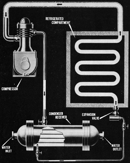
Figure 6-1a. Diagram of principle of refrigeration.
24
line between the low- and high-pressure sides
is the discharge valve of the compressor.
6A10. High-pressure side. The remainder of
the cycle from the discharge valve of the compressor
through the condenser, receiver, and
expansion valve to its orifice is called the
high-pressure side. The dividing line between
the high- and low-pressure sides is the thermostatic expansion valve.
B. HEAT ACTION IN THE VARIOUS ELEMENTS OF THE CYCLE
6B1. In the evaporator. The evaporator is
the point at which the heat from articles or
air to be cooled enters the refrigerating system. This heat causes the Freon 12 to boil,
and the rapid boiling carries tiny droplets of
the liquid into the vapor. The Freon 12 at this
stage is therefore a wet vapor. However, the
design of the system is such that a little more
heat is admitted to the evaporator than is required to produce saturated vapor. An additional superheat (about ten degrees) also
enters the vapor in the evaporator. This super
heat is kept fairly constant by the expansion
valve. The superheat eliminates the wetness
of the vapor, and prevents excessive frosting
of lines and compressor and the possibility
of carrying liquid over into the compressor. It
also increases the efficiency of operation.
6B2. In the compressor. So far, the temperature of the boiling Freon 12 has not been
raised (except for the slight superheat), because the heat entering it in the evaporator
is latent heat of vaporization which serves
only to turn the liquid into a vapor. But in
the compressor, after the vapor has passed
through the intake, or suction, valve, it is
sealed off from its originating liquid. The
heat now entering the vapor by the compression in the compressor, or heat pump, is more
than sufficient to raise its temperature to the
boiling point that corresponds to the new
higher pressure. Thus the high-pressure vapor
is further superheated.
6B3. Purposes of the compressor. The compressor serves several purposes
1. By suction, it removes the vapor from the
evaporator as rapidly as it is formed so that
there is always room for more vapor.
2. The steady suction tends to maintain a
practically constant pressure in the evaporator; hence, the temperature of the refrigerant
therein remains fairly constant.
3. It keeps fluid circulating in the system,
thus maintaining continuous refrigeration.
4. It compresses the low-pressure vapor to
a high-pressure vapor, whereby the condensation point is raised to such a degree that the
vapor can be condensed by the available cooling water.
5. It produces a difference of pressure on
the two sides of the expansion valve, thereby
causing a steady and positive flow of the refrigerant through that valve.
6B4. Necessity for the compressor. The
compressor is an essential part of every mechanical refrigerating system. The question
is often asked: Why is it necessary to compress refrigerants? Fundamentally, the reason
is this: All the liquids used as refrigerants
possess the peculiar property of boiling at
low temperatures under atmospheric pressure.
If one of these liquids were in an uncovered
dish in the open air, it would boil briskly
without any fire under it. Even on a cold day,
the mere heat in the air is enough to make it
boil. It was seen in Section 3D6, that the boiling point of a liquid varies with the pressure
on it. By confining a liquid refrigerant in an
airtight container (a refrigerating system is
such an airtight container), we can increase
or decrease the pressure on the liquid and
thus place its boiling temperature at any degree we desire. By increasing the pressure on
a vapor, we cause its condensation point to
rise.
Now the refrigerant liquid in the evaporator has boiled at a low temperature. This low
temperature vapor must give up its excess
heat and condense back to the liquid state before it can be used again. Another such liquid
cannot be used a second time for this purpose,
for that would need still another, and so on
endlessly. It is, necessary to use an easily
available fluid, such as air or water. But the
ordinary temperatures of water or air are considerably above the condensation temperature
of the vapor. Fortunately, when a vapor is
compressed, its temperature rises. Therefore,
25
the vapor is compressed so that its temperature rises to such a degree above the ordinary
temperature of the available water that the
heat can transfer (in the condenser) from the
now higher-temperature vapor to the water.
6B5. In the condenser. The excess heat enters the refrigerant while it is in the evaporator. Since the refrigerating system is a
continuous circuit in which a given quantity
of Freon 12 flows around and around, it is
necessary to remove this excess heat before
it can return to the evaporator. The condenser is the point at which this heat is removed.
In the condenser, the refrigerant passes
around the tubes through which sea water is
pumped. A fresh supply of sea water is continuously pumped through, and is not used
again as is the primary refrigerant.
The unwanted heat transfers by conduction
through the walls of the tubes from the refrigerant vapor to the sea water. More heat
is discharged here than enters the refrigerant
in the evaporator, for extra heat equaling the
work done upon the vapor enters the vapor
while it is being compressed.
It should be remembered that the temperature of the vapor, when it gets into the condenser, depends upon the temperature of the
cooling medium, that is, the sea water. The
compressor must produce a pressure on the
vapor always high enough to make the vapor
condense at the temperature in the condenser.
Therefore; the condensing temperature that
exists in the condenser determines the minimum discharge pressure of the compressor.
Naturally, the sea water inside the condenser does not remain at the same temperature. The heat leaving the vapor enters the
water, and the water temperature rises. How
ever, the continuous flow of water through
the tube prevents this rise from getting too
high. Actually the rise within the condenser
is only a few degrees.
The heat transfer inside the condenser,
therefore, is as follows: First the temperature
of the vapor drops as the superheat leaves it.
When it reaches the condensation point corresponding to the pressure, the vapor becomes
a saturated vapor, and as such, if further heat
is removed, it must condense. The temperature
remains constant while the latent heat
is departing during condensation. The condensed liquid, in the bottom of the condenser
shell or tank, is not in contact with the entering section of the tubing through which the
water flows. The heat in the refrigerant liquid
is now sensible heat and therefore it drops
again in temperature by a small additional
amount. The whole operation within the condenser is a constant-pressure process.
a. Necessity for subcooling in the condenser. Subcooling, or lowering the temperature of the liquid refrigerant below its
saturation, or boiling, point, is essential before it reaches the expansion valve. This
subcooling is necessary to insure that vapor
mist or vapor bubbles are not contained in the
condensed liquid. If the condensed liquid
were allowed to remain at its saturation temperature probably only vapor bubbles would
be present, either as a result of being carried
uncondensed from the compressor vapor, or
as a result of some slight evaporation in the
line from the receiver to the expansion valve.
Subcooling in the condenser prevents this
possibility.
1. The orifice in the expansion valve is designed to pass the correct amount of liquid
refrigerant to furnish the desired cooling. If
vapor mist is mixed with the liquid, a smaller
amount of liquid passes through the expansion
valve, and the system cannot produce its full
rate of refrigeration.
2. Refrigeration is produced only by the
alternate evaporation and condensation of the
refrigerant. If any vapor passes around the
cycle uncondensed, it produces no refrigeration, and the energy used in pumping it
through the system is wasted.
Thus it is evident that the subcooling in the
condenser plays a most important part in the
efficient operation of the system.
6B6. In the receiver. No heat action takes
place within the receiver, that is, the receiver
plays no part in the heat cycle. It serves as a
momentary storage for the liquid refrigerant
that leaves the condenser, and as a seal between the vapor in the condenser and the
liquid as it flows into the expansion valves. In
some types of condensers, the bottom part of
the shell or tank is used as a receiver.
26
6B7. In the thermostatic expansion valve.
The purposes of this valve are 1) to control
the quantity of liquid refrigerant passing into
the evaporators; 2) to maintain a constant
pressure on the refrigerant so that the super
heat is held practically constant regardless of
the suction pressure; 3) to disperse the liquid;
and 4) to prevent the liquid from surging
toward the compressor. The total heat present
remains constant.
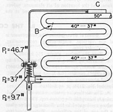
a. Theory of operation. Consider a refrigerant evaporator in an air-conditioning unit
operating with Freon 12 at 37 psi suction pressure. The Freon 12 temperature at saturation
at 37 psi is 40 degrees. As long as any liquid exists
at this suction pressure, the temperature remains at 40 degrees.
Freon 12 moving along within a coil absorbs
heat from the air outside the coil until (B,
Figure 6-2) it has absorbed its latent heat of
evaporation. At this point all the liquid has
evaporated and the vapor is saturated. Any
additional heat absorbed from the surrounding
air raises the temperature of the vapor but the
pressure remains at 37 psi. When the suction
gas or vapor reaches the point of the thermal
bulb attachment (C), it is superheated according to the thermal valve setting; for example,
10 degrees.
Neglecting heat transfer loss from the suction line to the thermal bulb, the temperature
of the liquid Freon 12 within the bulb is 50 degrees,
the temperature of the suction gas at this
point. The pressure within the bulb, and
consequently within the power assembly, is
46.7 psi (P1). This force tends to push the valve
diaphragm down, opening the valve. Opposing
this force is the pressure, 37 psi (P2), with the
evaporator at 40 degrees evaporator temperature, and
the force (Ps) exerted by the spring on the
diaphragm. To keep the valve in equilibrium
at 10 degrees superheat, this spring is externally adjusted to exert a force of 9.7 psi on the diaphragm.
b. Thermostatic expansion valve action. If
the superheat in the suction gas increases, as
in the case of an increase in load, the thermal
bulb temperature and its corresponding pressure increase, exerting a greater pressure on
the diaphragm. This causes the valve to open
to allow a sufficient increase in flow of refrigerant to restore the superheat to 10 degrees. If the
superheat decreases because of a falling off
in the load, the pressure in the thermal bulb,
and consequently, in the power element, decreases and tends to close the valve. The flow
of refrigerant is throttled enough to increase
the superheat to 10 degrees. Thus, it is evident that
the function of the thermostatic expansion
valve is twofold: 1) automatic expansion control, and 2) prevention of the liquid refrigerant
from surging back to the compressor.
Close control of superheat results in the
greatest coil efficiency. However, superheat
should never be maintained below 5 degrees because
of the danger of the liquid refrigerant surging
back to the compressor. Nor should a coil be
operated with superheat in excess of 15 degrees because of the inefficiency of operation beyond
that point.