5A1. Importance of boresighting. Torpedoes, compared to guns, are relatively inaccurate and
there may be a tendency toward slipshod
boresighting. At 4,000 yards, an error of 1 degrees
in boresighting results in an error of 210 feet,
about half the length of an average ship. Thus
it can be seen that boresighting must be sufficiently accurate to prevent errors greater than
1/4 degrees, and even greater refinement is desirable.
In two-power periscopes, the line of sight
usually is changed when low power is thrown in.
Consequently, in both torpedo firing and boresighting the high power of the periscope should
be used in which no movable lenses are in the
line of sight.
B. BORESIGHTING PROCEDURE
5B1. Boresighting submarine torpedo tubes. When
a periscope azimuth circle reads 0 degrees (or 180 degrees
for the stern tubes), the line of sight through
the periscope should be parallel to, or coincident
with, the mean axis of the torpedo tubes.
The object of boresighting is to determine
whether this condition exists, and if it does not,
to determine the relative alignment of the
forward and after tube nests and the periscope
with the azimuth circle.
Boresighting is done while the submarine
is on the ways of a marine railway or in drydock,
preferably on a cloudy day or at night with low
wind velocity. Boresighting should not be done
with strong sun on one side of the vessel since
the unequal heating produces a slight curvature
in the vessel's centerline. To create a condition
of low wind velocity, it may be necessary to
erect canvas shields, extending from the main
deck to the ground on both sides of the bow
and stern, to protect the outside plumb bob
lines from the wind.
To establish the mean axis of each set of tube
nests, two main targets must be erected for
each nest of tubes. The usual arrangement
consists of one set of targets inside and another
set outside, fastened to the ship's structure.
The outside targets must be as far away from the
ends of the torpedo tubes as practicable (Figures
5-2 and 5-3). The two inside targets must be
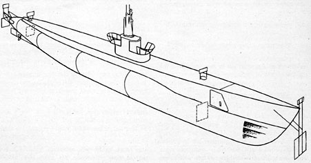
Figure 5-1. Construction of four main targets and four auxiliary targets in perspective.
276
located under the torpedo loading hatch openings (Figure 5-1), so that a plumb line can be
dropped from topside to it. Small auxiliary
targets on which to plumb up and sight, are
located topside above the four main targets.
A set of boresight gages, which fits snugly
into the tube bore at each end, is necessary.
One boresight gage has a small peephole in its
center axis (Figure 5-4) while the center axis
of the other (Figure 5-5) is bored to receive a
boresight gage bushing of a press fit. The bushing is threaded in the bore to receive the external
threads of the boresight telescope (Figure 5-6).
5B2. Establishing the centerlines. The first operation is to establish the centerline of each tube
on both inside and outside targets.
1. Starting with the outside target, set up
the boresight gage with the small peephole
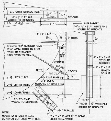
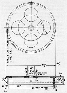
Figure 5-2. Construction of bow main outside target and auxiliary target.
277
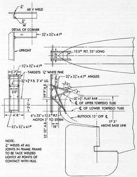
Figure 5-3. Construction of stern main outside target and auxiliary target.
278
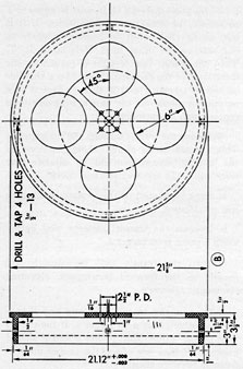
Figure 5-4. Boresight gage with peephole.
(Figure 5-4) at the muzzle end of the tube,
and the boresight gage for the boresight telescope
at the breech end (Figure 5-5).
2. Engage the external threads of the boresight telescope in the internal threads of the
boresight gage bushing (Figure 5-6) and secure
the boresight lock ring tightly with a spanner
wrench.
3. Focus the telescope and adjust the crosswires to the peephole at the muzzle end of the
tube.
4. Illuminate the peephole by holding a
portable light or flashlight behind it.
5. Remove the boresight gage with the peephole from the muzzle end of the tube and focus
the telescope on the target.
6. Have a helper mark the intersection of the
crossline on the target.
7. Carry out this procedure with the remaining tubes of the nest. Project the tube
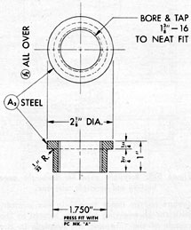
Figure 5-5. Boresight gage for boresight gage
bushing and boresight telescope.
centers on the inside targets in like manner,
with the boresighting telescope located in the
muzzle of the tube and the peephole in the
breech end.
8. Repeat the procedure used for the forward nest with the stern nest of tubes. At this
point there are four targets, each bearing marks
corresponding to the number of tubes in each
nest; that is, for the current 310-foot submarine,
there will be two targets with six marks forward
(Figure 5-7), and two targets with four marks
aft (Figure 5-8).
5B3. Marking off the targets. The next operation
consists of marking off the individual targets.
1. Join the projected intersection points with
straight lines as indicated. Measure distances
on targets as shown in the appropriate figure.
5B4. Finding mean axes. 1. Upon completion of
target marking, drop a plumb line from the
plumb line adjustment adapter attached to the
target to the lower target (Figure 5-9).
279
2. Have the plumb line adjusted until it
splits the various bisecting and diagonal points.
Mark this line, representing the horizontal
point of impact, by inserting a nail in the top
of the upper target.
3. Follow the same procedure for all four
targets. At this point, there are four nails, one
on each of the upper targets, and a line between
the nails on the two targets of any nest to
represent the mean axis of that nest.
Figure 5-6. Boresight gage bushing for insertion
in boresight gage Find attachment of boresight
telescope.
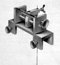
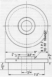
5B5. Paralleling the mean axes. With the periscope
removed from the submarine, provide a transit
holding fixture on the periscope opening atop
the periscope support. (See Figure 5-10 for construction of this fixture.) With the transit
parallel to the mean axis of the forward nest
of tubes, as represented-by a line through the
nails referred to above, the paralleling is, done
as follows:
1. Sight the transit on the nail established
on target 2 (Figure 5-8) and project this point
to target 1.
2. Measure the distance m. Then lay off
distance T, which is equal to a/b X M. Mark this
point and project it down to target 2.
3. Measure distance U. It must be equal to T
to satisfy the condition of parallelism. If it is
not, swing the transit in azimuth slightly to
one side or the other until U is equal to T.
Then the transit line of sight is parallel to the
mean axis of the forward tubes. Mark this line
on top of targets 1 and 2, then project it to a
permanent place on the ship's structure, and
centerpunch a benchmark.
4. Swing the transit through 180 degrees in azimuth.
This azimuth swing of 180 degrees should be done by
the double reverse method to obviate any
error which the transit itself may have.
a. Sight the transit on the forward benchmark
just established.
b. Depress the transit telescope and lightly
mark a point p on target 3.
c. Turn the transit 180 degrees in azimuth and
resight on the forward benchmark, elevating
the transit telescope.
d. Depress the transit telescope and lightly
mark another point p on target 3. If the transit
is in proper adjustment, points p and P should
coincide. If they are apart, the proper mark is
halfway between them.
e. Mark this point on target 3 and then
project it aft to target 4. Continue the line to a
permanent place on the hull and prick punch
another benchmark. At this point there is,
besides the nails already mentioned above a
mark on each upper target. A line through these
marks represents a line parallel to the mean
axis of the forward tubes. Two benchmarks on
the hull represent the same line.
5. Measure the distance V and W. The
tangent of the angular difference between the
mean lines of the forward and stern tubes is
((W - V) / 12D), if W and V are measured in inches and
D is measured in feet. This tangent represents
the total angle of error, and if it is less than
0 degrees 5', it is considered negligible. If this error is
greater, the officer in charge of boresighting
should split the errors between the bow and
stern nests and establish the permanent benchmarks accordingly. The required transverse
distance in inches between the temporary and
final forward benchmarks is equal to Re
280
(W - V), where e is the horizontal distance
from the center of the periscope to the benchmark measured in feet, and R is the ratio of
the final bow tube error to the total error. The
permanent stern benchmark must be 180 degrees
from the forward benchmark. If the error is
less than 0 degrees 5', the benchmarks as established
originally are considered permanent.
6. If periscope supports are not erected, the
same operation may be performed by setting
up a transit on the periscope support foundation. Set the transit in such position that the
nails in targets 1 and 2 line up. This places the
transit on the mean line of the forward tube nest.
Project this line aft. Turn the transit 180 degrees in
azimuth and proceed as before, placing the
temporary benchmarks at a convenient location
and calculating the angle between the line of the
forward and after tube nests. After the periscope
supports are installed, it is necessary only to
erect the transit atop the periscope supports
on the periscope line and parallel the line
between the temporary benchmarks. This operation may be performed as follows:
a. Set the transit on the fixture (Figure
5-10). This should be done on a rigid table.
b. Level the base of the fixture, using a level
and shims; then level the transit plate.
c. Carry the whole assembly atop the periscope supports and install it in the periscope
upper bearing.
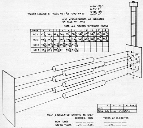
Figure 5-7. Two main targets of six tube nests in perspective.
281
d. Sight on the forward benchmark, project
a line aft using the double reverse method
described before, and mark a point next to the
stern benchmark.
e. Measure distance S between this point
and the benchmark.
f. Next to the forward benchmark, lay off a
distance l/n XS, where l is equal to the distance
from the forward benchmark to the periscope
position, and n is the distance between the after
benchmark and the periscope position. Mark this
forward point on the ship on the same side as
the after mark from the after benchmark.
g. Project this point aft 180 degrees with the transit
and mark another point next to the after benchmark. The distance from this point aft to the
original after benchmark must be equal to the
distance between the original forward benchmark and the mark laid off forward, and must
be on the same side of the ship. The permanent
benchmarks are then established on this parallel
line; this line being parallel to the mean axis
of the forward tubes.
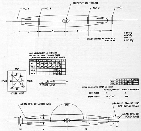
Figure 5-8. One four-tube nest target and one two-tube nest target showing position of auxiliary targets and
paralleling mean axes.
282
Figure 5-9. Plumb line adjustment adapter.
7. Periscopes, when installed, should be
trained on the forward benchmark and the
azimuth circle set on 0 degrees.
8. If the ship has a list, it is necessary to
place the axis of the transit in the longitudinal
centerline plane of the vessel and to project the
mean target points upward parallel to the same
line.
9. Final angles of error less than 5' of arc
maybe considered as negligible.
10. When any submarine has undergone
extensive depth charging, or the periscope has
been damaged, because of a collision or an ice
flow, the repairman must check the periscope
alignment to the bow and stern benchmarks to
ascertain the alignment of the periscope supports.