V. REASSEMBLY OF THE UPPER AND LOWER TELESCOPE SYSTEMS
4V1. Reassembly of the upper telescope system.
The upper telescope system is reassembled in
the following manner:
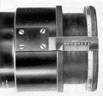
1. Using an air hose, blow out the upper
telescope system Part II consisting of the
second, third, and fourth inner tube sections
(Figure 4-21).
2. Screw the threaded periphery of the upper
part of the fourth inner tube section upper end
coupling (5) into the internal threaded section
in the lower part of the fifth inner tube section
(34, Figure 4-20) of the upper telescope system
Part I.
3. Insert and secure the four lockscrews (35),
inserting them in countersunk clearance holes in
the lower part of the fifth inner tube section
(34) and screw them into tapped holes in the
upper alignment support section of the fourth
inner tube section upper end coupling (5,
Figure 4-21). This secures the upper telescope
system Part I and Part II together.
4V2. Reassembly of the lower telescope system.
The lower telescope system is reassembled in
the following manner:
1. Connect the eyepiece skeleton assembly
(Figure 4-28) to the lower part of the first inner
tube section assembly (Figure 4-27).
2. Screw the internal threaded section of
the eyepiece skeleton upper part (42, Figure
4-28) on the threaded periphery of the spider
bearing (3, Figure 4-27).
3. Insert and secure the four lockscrews
(37, Figure 4-28), inserting them in countersunk
clearance holes in the counterweight bearing
section of the eyepiece skeleton (42) and screw
them into tapped holes in the spider bearing
lower alignment support section (3, Figure
4-27).
4. Connect the objective operating mechanism assembly (Figure 4-23) to the first inner
tube section assembly (Figure 4-27).
5. Screw the internal threaded section in
the lower part of the track sleeve (2, Figure
4-23) on the threaded periphery located in the
upper part of the first inner tube section upper
end coupling (11, Figure 4-27).
6. Insert and secure the four lockscrews
(23, Figure 4-23), inserting them in countersunk
clearance holes in the lower part of the track
sleeve (2) and screwing them into tapped holes
in the upper alignment support section of the first
inner tube section upper end coupling (11,
Figure 4-27). This secures the objective operating
mechanism assembly and the first inner tube
section assembly together.
222
7. Place the stadimeter transmission shaft
coupling (14, Figure 4-23) on the lower part
of the operating gear pinion shaft (13) and
secure it to the shaft with a taper pin (33).
8. Place the objective operating mechanism
assembly and the eyepiece skeleton assembly
attached to the first inner tube section assembly
in two V-blocks on the optical I-beam bench.
9. Unscrew the eyepiece lens mount (19,
Figure 4-28), carrying with it the eyepiece lens
(52), eyepiece lens clamp ring (16), and its lock
screw (41). The removal of the above outward
projecting assembly is necessary for the assembly
of the eyepiece box (11, Figure 4-29) to the
eyepiece skeleton (42, Figure 4-28).
10. Check the base of the eyepiece box (11,
Figure 4-29) to ascertain that the eyepiece
skeleton centering screw (12) is not secured in
place.
11. Assemble the outer tube and eyepiece box
rubber gasket (8) on the upper alignment support
section of the eyepiece box (11), resting it
against the sealing shoulder located preceding
the threaded periphery. Check the eyepiece box
and eyepiece skeleton assembly to ascertain
the elimination of all inward and external
projecting parts and to make sure that nothing
restricts the assembly of the eyepiece box (11).
12. Place the eyepiece box (11) over the
eyepiece skeleton assembly (Figure 4-28), guiding it on slowly and carefully. It is carried on
the narrow alignment shoulder of the large
shoulder flange of the eyepiece skeleton (42).
Engage the reamed dowel pin holes of the
eyepiece box upper face over the downward
protruding dowel pins (36) in the eyepiece
skeleton large shoulder flange.
13. Insert and secure the eight lockscrews
(31). These lockscrews are inserted with the
counterweight (25) at its extreme upward
position. The lockscrews are inserted in the
clearance holes in the eyepiece skeleton (42)
large shoulder flange and screwed into tapped
holes in the upper face of the eyepiece box (11,
Figure 4-29).
14. Place the stadimeter transmission shaft
(22, Figure 4-27) in the stuffing box section
of the eyepiece box face (11, Figure 4-29).
Guide the shaft as it is carried upward slowly
through the clearance hole in the large shoulder
flange of the eyepiece skeleton (42, Figure
4-28), and counterweight (25).
15. Place the lower thrust collar (4, Figure
4-27) on the stadimeter transmission shaft
(22) and carry the shaft through the bearing
hole in the spider (2).
16. Place the upper thrust collar (4) on the
stadimeter transmission shaft, (22) and carry
the shaft upward through the clearance hole in
the soldered bracket (23) located on the central
part of the first inner tube section periphery (1).
17. Line up the position of the taper pin
holes in the stadimeter transmission shaft
coupling (14, Figure 4-23) and the stadimeter
transmission shaft (22, Figure 4-27). Insert
two temporary lockscrews in tapped holes in
the coupling until completion of procedure
stated in Section 4V11.
18. Place the two thrust collars (4) next
to the side faces of the cast bearing projection
of the spider (2) and secure them with two taper
pins (10).
19. Place the eyepiece drive packing gland
assembly stuffing box body gasket (11, Figure
4-35) on the counterbored face of the eyepiece
box (11, Figure 4-29) for this assembly.
20. Place the counterweight (25, Figure
4-28) at the extreme upward limit of its travel
(the plus position).
21. Place the female coupling section (3,
Figure 4-39) of the focusing knob assembly
on the square section of the eyepiece drive
actuating shaft (12, Figure 4-35) of the eyepiece
drive packing gland assembly. Check the reference punch mark on the eyepiece drive actuating
shaft (12) and the corresponding reference mark
on the female coupling section (3, Figure 4-39)
for proper alignment.
22. Check the +1 1/2 diopter setting with the
stationary zero reference line of the knob
bracket hub (7). The +1 1/2 diopter setting should
be turned to a slight overtravel of the stationary
zero diopter reference line.
23. Place the eyepiece drive packing gland
assembly together with the attached focusing
223
knob assembly in its opening in the eyepiece
box (11, Figure 4-29). Align the rectangular
base of the knob bracket (7, Figure 4-39) with
the recess face in the eyepiece box on the stuffing
box body rubber gasket (11, Figure 4-35).
24. The eyepiece drive mechanism bevel
gear (1) attached to the eyepiece drive actuating
shaft (12) should engage into mesh correctly
with the eyepiece prism shift bevel gear (11,
Figure 4-28) of the eyepiece skeleton assembly.
25. Remove the focusing knob assembly
(Figure 4-39) from the eyepiece drive packing
gland assembly (Figure 4-35).
26. Rotate the stuffing box body of the eyepiece drive packing gland assembly so that
reference numerals on the stuffing box body
flange face coincide with the reference numerals
on the eyepiece box recess face (11, Figure 4-29).
27. Insert and secure the six lockscrews
(3, Figure 4-35) inserting them into countersunk
clearance holes in the stuffing box body flange
(6) and screwing them into tapped holes in the
eyepiece box counterbored seat.
28. Replace the focusing knob assembly
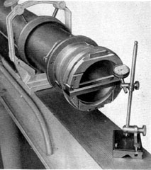
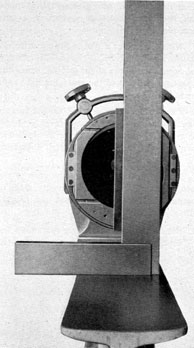
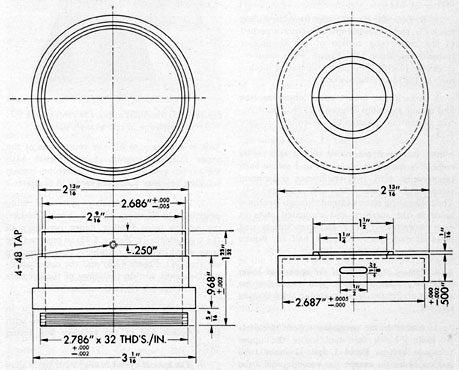
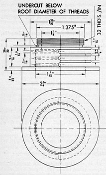
(Figure 4-39) on the square section of the
Figure 4-50. Special eyepiece alignment jig
diagram.
eyepiece drive actuating shaft (12, Figure 4-35)
in the same manner as described under Step 21.
29. Check the rectangular flange of the knob
bracket (7, Figure 4-39) to ascertain that the two
dowel pins (8) engage in the dowel pin holes
in the eyepiece box recess face.
30. Insert and secure the four lockscrews
(10). These lockscrews are inserted in countersunk clearance holes in the knob bracket
rectangular flange (7) and screwed into tapped
holes in the eyepiece box.
31. Place the eyepiece skeleton centering
screw lead washer (13, Figure 4-29) on the
shoulder of the centering screw (12), inserting
the centering screw in the base of the eyepiece
box (11). The centering screw extends into the
reamed hole in the eyepiece skeleton base (42,
Figure 4-28) and screws into a tapped hole in
the eyepiece box base. Secure the centering
screw with a large screw driver blade, using
a small wrench on the blade, to insure the
hermetical seal of this opening.
32. Using a special wrench attached to the
male tang section of the stadimeter transmission shaft (22, Figure 4-27) rotate the shaft,
placing the objective operating mechanism
at the observing position.
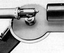
4V3. Alignment of the 90 degrees rotation of the objective operating mechanism. The 90 degrees rotation of
the objective operating mechanism is aligned
in the following manner:
1. Place the lower telescope system described
in Section 4V2 in two V-blocks on the optical
I-beam bench. Face the objective operating
mechanism toward the end of the optical
I-beam bench.
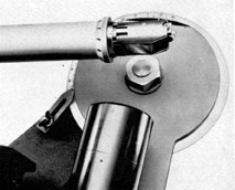
2. With the two special clamp brackets
attached to the V-blocks, line up the eyepiece
end of this assembly with the horizontal and
perpendicular plane of the optical I-beam
bench.
3. Place the threaded periphery of the special
eyepiece alignment jig (Figure 4-50) in the
internal threaded section in the eyepiece prism
front retaining plate (24, Figure 4-28) of the eyepiece skeleton assembly. Screw the jig into this
front retaining plate until the shoulder of the
224
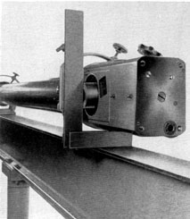
Figure 4-51. Lining up the eyepiece jig with
machinist's square.
jig attains a tight metal to metal contact with
the projecting cylindrical shoulder of this
retaining plate.
4. Using a large machinist square, line up
the special eyepiece jig to a true horizontal
plane. The outer face of the alignment jig is
aligned vertically with the vertical blade of
the square in the following-manner:
5. Rotate the complete assembly in the
V-blocks until the outer face of the alignment
jig is parallel to the vertical blade of the square
(Figure 4-51). The base of the square is placed
on the I-beam surface with the 90 degrees blade extending upward vertically.
6. Secure the V-block clamps by turning
the adjusting knobs as shown on the above
illustration. These clamp the lower telescope
system tight in the V-blocks. Check the face
of the alignment jig note and correct any change
which may have taken place while clamping.
7. When the special eyepiece jig is in a true
horizontal plane and well clamped] determine
the parallelism of the observing position of
the sliding track (3, Figure 4-23) in the following
manner:
8. Rotate the special wrench attached to
the male tang section of the stadimeter
transmission shaft (22, Figure 4-27) until the peripheries of the mounting plates (5, Figure 4-23)
of the objective operating mechanism are in
coincidence.
9. Insert the 90 degrees alignment straight-edge
(Figure 4-52) with the four extension lugs of
the straight-edge a push fit in the opposite
elongated slots of the sliding track large shoulder
flange (3, Figure 4-23). The straight-edge of
this device locks the mounting plates (5) and
the operating mechanism to provide only the
90 degrees rotation.
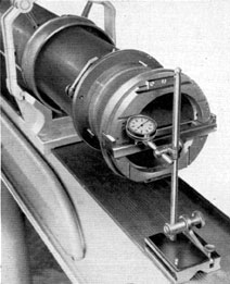
10. Using a dial indicator attached to a surface
gage, determine the parallelism of the straight-edge with the horizontal surface of the optical
I-beam bench.
11. Place the surface gage on the surface of
the optical I-beam bench, with the dial indicator,
set with sufficient tension on the straight-edge
(Figure 4-53).
12. Keep a firm pressure on the base of the
surface gage while checking throughout the
length of the straight-edge.
13. Note the dial indicator for any variation
while traveling the length of the straight-edge
(Figure 4-54).
14. If variation is noticed, it indicates that
wear has taken place at the detent pawl rest
stop, which is the end of the circumferential
slot of the track sleeve (2, Figure 4-23) for the
observing position.
225
Figure 4-53. Dial indicator attached to surface
gage, on 90 degrees straight-edge at the left side for
range position.
15. Remove the six lockscrews (26), unscrewing them from the tapped holes in the
opposite raised mounts of the track sleeve (2).
Remove the detent pawl spring (6), and swing
the detent pawl (7) clear for the removal of the
detent pawl rest (8)
16. Remove the two long and two short
lockscrews (9 and 1-0), unscrewing then from
the tapped holes in the sliding track (2). Remove
the detent pawl rest (8).
17. The detent pawl rest (8) can be built
up by welding or it can be renewed. If built up
by welding, it can be worked down on a grinding
wheel, using a trial and error checking method.
18. After building up the detent pawl rest
(8), grind it down until it contacts the end
of the track sleeve circumferential slot (2),
leaving the straight-edge parallel with the
surface of the optical I-beam. Use the dial
indicator each time in the same manner as
directed in step (13), and secure the detent
pawl rest (8) each time with the long and short
lockscrews (9 and 10).
Figure 4-54. Dial indicator attached to surface
gage on 90 degrees straight-edge at the right side for
range position.
19. The opposite stop, or end, of the circumferential slot in the track sleeve (2) is
the contact stop position of the opposite face
of the detent pawl rest (8) in the course-angle
position.
20. The course-angle stop position of the
circumferential slot in the track sleeve (2)
has minor usage in the service. Therefore, no
building up of the detent pawl rest (8) should
be required.
21. Turn the special wrench attached to the
male tang section of the stadimeter transmission
shaft (22) clockwise until the course angle of the
detent pawl rest ( 8) is against the end of the
circumferential slot in the track sleeve (2).
22. Place the machinist square on the surface
of the optical I-beam bench and slide the blade
of the square in contact with the straight-edge
(Figure 4-55). Check the parallelism of the
straight-edge with the 90 degrees vertical blade of
the square.
23. Build up and grind down this contact
face of the detent pawl rest (8, Figure 4-23)
for the course-angle position by following the
procedure stated under Step 18; in this case,
however, the square is used each time.
226
24. Secure the detent pawl rest (8) with the
two long and two short lockscrews (9 and 10)
after completion of the alignment of the 90 degrees
movement for the observation and course-angle
positions.
25. Swing the detent pawls (7) inward, and
check their engagement in the 90 degrees V-groove
notch in the detent pawl rest (8) for the observing and course-angle positions. The detent
pawls should retain the detent pawl rest against
the opposite circumferential slot stops for either
position. Should the detent pawls (7) require
building up for proper engagement, they can be
repaired in the same manner as the detent pawl
rest (8).
26. Swing the detent pawls (7) inward and
place the spring (6) so that it overlaps both
detent pawls. Secure it to the opposite raised
mounts of the track sleeve (2) with six lockscrews
(26).
27. Remove the straight-edge from the sliding
track (3), and rotate the special wrench attached
to the male tang section of the stadimeter
transmission shaft (22, Figure 4-27) counter-clockwise, placing the objective operating mechanism in the observing position.
28. Attach the lower (split) objective lens
and mount assembly (Figure 4-22) to the objective operating mechanism assembly (Figure
4-23).
29. Place each assembled mount half on its
respective mounting plate (S), and secure each
temporarily with two stadimeter collimating
screws (13, Figure 4-22) and washers (14).
The collimating screws extend through clearance
holes in the washers and elongated slots in
each mount half (1 and 2) and screw into tapped
holes in each mounting plate half (5, Figure
4-23).
4V4. Primary collimation of the upper and lower
telescope systems. The upper and lower telescope
systems are primarily collimated in the following
manner:
1. Assemble the necessary spacer thickness
on each V-block face and finder the upper
telescope system Parts I and II inner tube
section bearings, except the second inner tube
section lower end coupling (26, Figure 4-21).
Figure 4-55. Machinist's square in contact with 90 degrees
straight-edge at course-angle position.
This is necessary to lift the center axis of the
upper telescope system in coincidence with
the center axis of the lower telescope system
coupling bearings which are larger in diameter.
2. Place the lower telescope system assembly
described in Section 4V2 in two V-blocks,
resting the large bearing flange periphery of
the track sleeve (2, Figure 4-23) in one, and the
large shoulder flange periphery of the eyepiece
skeleton (42, Figure 4-28) and the upper alignment support section periphery of the eyepiece
box (11, Figure 4-29) in the other.
3. Rotate the lower telescope system in
the two V-blocks for vertical collimation, with
the eyepiece end of the eyepiece box facing
upward.
4. The special eyepiece alignment jig (Figure
4-50) inserted in Section 4V3, Step 3, remains
227
in place for checking and placing the eyepiece
end of the lower telescope system in a true
vertical plane.
5. With the use of a dial indicator attached
to a surface gage, determine the parallel position
of the outer face of the alignment jig, hence the
true vertical position of the emerging light rays
in the following manner:
6. The surface gage is used on the surface
of the optical I-beam bench (Figure 4-58),
with the dial indicator set with sufficient
tension on the outer face of the alignment
jig.
7. Keep a firm pressure on the base of the
surface gage, while checking opposite sides of
the outer face of the alignment jig (Figure
4-59).
8. Rotate the lower telescope system on the
two V-blocks until both outer faces opposite the
bored hole in the jig indicate equal height or
are parallel to the surface of the optical I-beam
bench, as determined by the dial indicator
pointer. This places the centerline of the emerging rays of light in the vertical direction, and
the light rays enter the head prism in the same
direction.
9. Secure the V-block clamps by turning
the adjusting knobs of the clamp brackets,
as shown on Figure 4-58. Check the face of the
alignment jig again to detect any variation
and make corrections in the same manner as
before.
10. Slide the upper telescope system down
on the optical I-beam until it is near the aligned
lower telescope system assembly.
11. Line up the reference marks of the second
inner tube section lower end coupling (26,
Figure 4-21), checking it by the coupling sleeve
(34, Figure 4-23) in its proper coincidence
relationship with the track sleeve (2) reference
marks.
12. Holding the coupling sleeve (34) on the
undercut alignment support sections of the track
sleeve (2) and the second inner tube section
lower end coupling (26, Figure 4-21), slide the
upper telescope system Parts I and II downward
snugly against the coupling sleeve. This permits
the coupling sleeve to fit snugly between the
bearing shoulders of the track sleeve (2, Figure
4-23) and the second inner tube section lower
end coupling (26 Figure 4-21). Remove the
coupling sleeve and place it in a convenient
place until it is required again for distance
measurement or for reassembly.
13. Remove the eyepiece alignment jig (Figure 4-50) and replace the assembled eyepiece
lens mount (19, Figure 4-28) by screwing
it into the eyepiece prism front retaining plate
(24). Check the inner and outer surfaces of
the eyepiece lens (52) for cleanliness before
replacement.
14. Remove the four lockscrews (12, Figure
4-20) from the upper part of the reducing
coupling (2), unscrewing them from the tapped
holes in the lower alignment support section
of the first reduced tube section (1).
15. Unscrew the first reduced tube section (1)
from the internal upper part of the reducing
coupling (2).
16. Screw the temporary mechanical crosswire
adapter (Figure 4-56) into the threaded counterbored section in the lower part of the first
reduced tube section (1, Figure 4-20).
17. Replace the first reduced tube section (1),
screwing its lower threaded periphery into the
internal threaded upper section in the reducing
coupling (2). The lower part of the temporary
Figure 4-58. Dial indicator determination of true
vertical position on the left side face of the eyepiece
alignment jig.
229
crosswise adapter is angularly adjusted to suit
the observer by following the directions stated
in Step 15, and releasing the lockscrew of the
adapter. Rotate the lower part and replace the
first reduced tube section (1).
18. The purpose of the temporary mechanical
crosswise adapter (Figure 4-56) is to establish
a target on which the upper objective lens is
focused; it also provides a reference point
from which the correct position of the collective
lens (21, Figure 4-20) is found.
19. The collective lens (21) is located 52 mm
from the focal plane toward the upper eyepiece
lens (20). This distance establishes the proper
lens separation of 394 mm between the upper
eyepiece lens and the collective lens and results
in the correct EFL of this eyepiece combination.
20. The EFL of the upper eyepiece lens must
be 432 mm to have the correct image size so that
Figure 4-59. Dial indicator determination of true
vertical position on the right side face of the eyepiece alignment jig.
the same operating gear (1, Figure 4-23) of the
objective operating mechanism assembly can
be used in both the Type II and Type III
periscopes.
21. The EFL of the upper eyepiece lens (20,
Figure 4-20) in the Type II is changed from
451 mm to 432 mm by the proper spacing of the
collective lens (21). The equivalent focal length
is found by using the following formula:
(F1 X F2) / (F1 + F2 - S) = EFL
F1 = 451 mm
F2 = 1326 mm
S = 394 mm
(451 X 1326) / (451 + 1326 - 394) = 432.3 mm
22. The primary collimation of the lower
telescope system is accomplished by the axial
movement of the upper objective lens and its
mount (41, 42, and 38). This brings the eyepiece
prism mount arrangement of the eyepiece
skeleton assembly (4-28) into focus with the
temporary crosswise adapter (Figure 4-56) to
obtain the minus and plus diopter settings.
23. In checking the essential travel of the
eyepiece prism mount (20, Figure 4-28) which
should be 25 mm, diopter lenses are used. Minus
and plus lenses must be inserted in the auxiliary
telescope adapter to obtain the minus and plus
diopter settings. This adapter is attached to the
objective end of the auxiliary telescope.
24. Insert a -1 1/2 diopter lens in the auxiliary
telescope adapter (Figure 4-57), moving the
counterweight up to its stop for full travel;
the stop is the spider bearing (3, Figure 4-27).
This causes the eyepiece prism mount to move
downward. Check the definition of the temporary
crossline adapter to be sure that it fades slightly
at the end of eyepiece prism travel. It is necessary
to move the upper objective lens mount (38)
and the lens (41 and 42, Figure 4-20) axially
to make this definition check.
25. Insert the +3 diopter lens in the auxiliary
telescope adapter (Figure 4-57), and bring the
counterweight downward to the lower stop, the
two lockscrews opposite each other in the eyepiece skeleton flange (42, Figure 4-28). These
lockscrew heads are longer than the other six
lockscrews in the eyepiece skeleton flange.
230
The downward movement of the counterweight
carries the eyepiece prism mount to the upward
position. Check the definition of the temporary
crosswire adapter to be sure that it fades slightly
at the end of the eyepiece prism travel. It may
be necessary to move the upper objective lens
mount (38) and the lens (41 and 42, Figure
4-20), axially to make this definition check
also.
26. Continue the procedure outlined in steps
24 and 25 until a slight overtravel is observed
at -3 and +1 1/2 diopters.
27. Upon completion of the collimation of
the lower telescope system, secure the upper
objective lens mount (38) in the fifth inner tube
section (34) with six lockscrews (36).
28. Now obtain the true zero diopter reading
of the diopter ring of the focusing knob assembly
(Figure 4-39). Using the auxiliary telescope
minus the adapter (Figure 4-57), focus the
eyepiece prism mount until sharp definition of
the temporary crosswire adapter is noted. The
diopter ring (9, Figure 4-39) should read -3/4
diopter at atmospheric pressure. This allowance
is compensated for when nitrogen of 7 1/2 psi
is introduced. Refer to Section 4V7.
29. Unscrew the first reduced tube section
(1, Figure 4-20) from the reducing coupling
(2). Remove the temporary crosswire adapter
(Figure 4-56), unscrewing it from the lower
part of the first reduced tube section.
30. Screw the diaphragm (13, Figure 4-20)
into the lower internal threads, of the first
reduced tube section (1) until its lockscrew
hole coincides with the tapped hole in the alignment support section tapped hole in the first
reduced tube section.
31. Insert and secure the lockscrew (7). The
lockscrew is inserted into a countersunk clearance hole in the lower alignment support section
of the first reduced tube section (1) and screwed
into a tapped hole in the diaphragm, (13).
32. Screw the first reduced tube section lower
threaded periphery (1) into the internal threaded
part of the reducing coupling (2).
33. Insert and secure the four lockscrews (12).
These lockscrews are inserted in countersunk
clearance holes in the reducing coupling (2)
and screwed into tapped holes in the first reduced
tube section lower alignment support section (1).
34. Move the upper eyepiece lens mount (6)
axially until a clear well-defined image of the
collimator reticule or target is apparent. Secure
the upper eyepiece lens mount with two lockscrews (10). Do not move the upper eyepiece
lens mount (6) in final collimation as this
destroys the correct lens separation between
the upper eyepiece lens (20) and the collective
lens (21).
4V5. Reassembly of the auxiliary upper and
lower telescope system assemblies to the upper
telescope system assembly. The auxiliary upper
and lower telescope systems are reassembled to
the upper telescope system assembly in the
following manner:
1. Screw the threaded periphery of the lower
part of the second reduced tube section (19,
Figure 4-19) into the internal threaded section
in the first reduced tube section upper part
(1, Figure 4-20). Support the attached auxiliary
upper telescope system assemblies while making
the connection of the auxiliary lower telescope
system assembly to the upper telescope system
assembly Part I.
2. Secure the first and second reduced tube
sections (1 and 19, Figures 4-20 and 4-19
respectively) with four lockscrews (8). These
lockscrews are inserted in countersunk clearance
holes in the first reduced tube section upper
part and screwed into tapped holes in the second
reduced tube section lower alignment support
section.
3. Place a support under the auxiliary upper
telescope system (Figure 4-18). This is necessary
because of the weight of the auxiliary upper and
lower telescope system assemblies. The support
is adjusted until the auxiliary upper telescope
system appears in the center axis of the other
telescope system assemblies. This is determined
by measurement from the surface of the optical
I-beam bench and by knowing the measurement
previously taken with a special cylindrical
disk. The disk diameter should coincide with
the diameter of the second tube section lower
end coupling (26, Figure 4-21).
4. Assemble the skeleton head assembly to a
special adapter (Figure 4-60). The adapter is a
231
Figure 4-60. Skeleton head assembly adapter, detail drawing.
sliding fit on the lower part of the skeleton head
frame (20, Figure 4-17) and is clamped to the
ninth reduced tube section (1, Figure 4-18).
The skeleton head assembly can then be used
temporarily; it is rotated for alignment with the
Kollmorgen universal collimator reticle (60,
Figure 4-69).
4V6. Final collimation of the four telescope systems in high power. Final collimation of the four
telescope systems in high power is accomplished
in the following manner:
1. The auxiliary upper and lower telescope
systems have been primarily collimated at
assembly. This primary step enables the repairman to arrive at the focal distance adjustments
in a much shorter time with the assurance that
the individual telescope systems have been
collimated.
2. Final collimation consists of coordinating the various telescope systems into a telescope combination; this requires minor fine
adjustments.
3. Place an auxiliary telescope at the eyepiece
end and set the periscope for -3/4, diopter at
atmospheric pressure.
4. Check the series of telescope systems on
the telemeter lens for clear definition. If necessary, move the auxiliary lower eyepiece lens
mount (13, Figure 4-19) axially to improve the
definition on the telemeter lens.
5. Check the eyepiece prism mount arrangement in focus on the telemeter lens, and observe
that the prescribed limits of -3 and +1 1/2
diopter travel are maintained.
6. Secure the auxiliary lower eyepiece lens
mount (13) with two lockscrews (17). These
lockscrews are inserted into countersunk clearance holes in the third reduced tube section (12)
and screwed into tapped holes in the mount.
7. Replacement of parts of the mechanical
or optical system necessitates a change in the
screw hole alignment. If no mechanical or
optical parts have been required during overhaul,
little difficulty should be experienced in arriving at the original screw alignment of the
manufacturer.
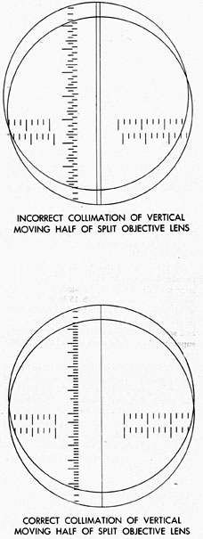
8. Temporary squaring of the telemeter lens
is required for the collimation of the lower
(split) objective lens with the Kollmorgen
universal collimator range reticle and the
telemeter lens.
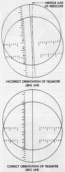
9. Displace the lower (split) objective lens
to the maximum displacement of the range
position. In this maximum displacement, the
telemeter lens line should be apparent to the observer as a solid line. If this vertical line appears
double or faded, it is necessary to rotate the
telemeter lens mount. Continue until the
telemeter lens line appears as a solid line.
232
4V7. Basic principles of collimating the Type II
periscope for compensation of nitrogen. The basic
principles of collimating the Type II periscope
(1.414) are described in the following manner:
In the ordinary sense the term collimator
implies that a target is placed in the focal plane
of an objective lens so that an image is formed
at infinity. This image, then, acts as an infinitely
distant object for the periscopic system that
is to be collimated.
The collimation of a periscope is complicated,
however, by the fact that the highly important
separations between the various lenses are
established with the lenses surrounded by air
at normal atmospheric pressure, whereas in
actual use the lenses are surrounded by nitrogen
at about 22.2 psi (absolute) pressure (atmospheric pressure plus 7.5 psi). The introduction
of this denser gas causes a relative decrease
in the index of refraction of the glass, effecting
a decrease in the refracting power of each lens
and an increase in the focal length of each lens
in the periscope.
If we understand that periscope collimation
means farming on the telemeter an image of an
infinitely distant object without parallax, we
may consider the effect of this denser gas on a)
all the lenses following the telemeter lens and
b) all the lenses preceding the telemeter lens.
It has been computed that the increase in focal
length of all lenses following the telemeter lens
can be compensated after gassing by moving the
eyepiece lens 3/4 diopter in a plus direction.
It is only necessary before collimating in air
to set the eyepiece at minus 3/4 diopter. After
the periscope is gassed and the eyepiece lens is
moved to the zero diopter setting, all change in
focal length of lenses following the telemeter
lens will have been compensated.
The lenses preceding the telemeter lens,
however, cannot be precompensated so easily,
and the problem may be approached in the
following manner: In the Type II periscope
(in high power) there is only one lens preceding
the telemeter lens, that is, the auxiliary upper
eyepiece lens with an equivalent focal length of
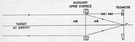
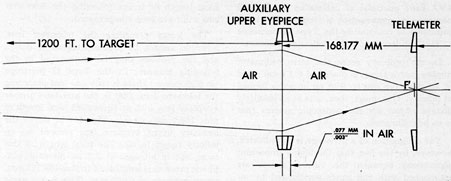
plus 168.1 mm in air. Figure 4-61 shows the
auxiliary upper eyepiece lens focused on an
infinity target in air. The focal length of this
same lens in nitrogen at 7.5 psi above atmospheric pressure is lengthened to plus 168.177 mm,
or an increase of 0.077 mm. This is the same
as saying that the focal length of the lens in
dense nitrogen is 1.00046 times that in air. In
order to adjust the lens in air so that there is no
parallax caused by the dense gas, a target distance, which is less than infinity and causes
the image to be formed 0.077 mm farther
from the lens, exactly in the plane which becomes
the back focal plane when the lens is surrounded
by the nitrogen, should be chosen. This
distance is found to be 1,200 feet.
The method of determining the conjugate
object-distance is calculated as follows:
The equivalent focal length (EFL) of the image-forming lens or auxiliary upper eyepiece
lens (Type II, high power) taken from the
optical detail drawing equals 168.1 mm.
The increase in EFL caused by gas pressure
is found by multiplying the 168.1 mm by
1.00046 and then subtracting 168.1 mm from
the result. A shorter method is to multiply
the 168.1 by 0.00046 and find the increase
directly.
Figure 4-61. Auxiliary eyepiece lens focused on an infinity target in air.
233
Figure 4-62. Ray diagram of periscope adjusted on 1200-foot target at atmospheric pressure.
This increase then, is divided into the square
of the EFL, or
Desired object-distance = (168.1)
X (168.1) = increase in EFL
or in the present example:
Object distance =
((168.1) X (168.1) / 0.077) =
28258 / 0.077 =
366,987 mm
Next, 366,987 mm is converted to feet by
dividing by 304.8 mm (the number of mm in
one foot). Thus, the desired object distance
equals 1,204 feet, or as stated above, 1,200 feet.
Summary: If the distance between the
auxiliary upper eyepiece lens and the telemeter
lens is adjusted so that a target 1,200 feet distant
is imaged exactly in the plane of the telemeter
lens when the lens is surrounded by air, when
the lens is surrounded by nitrogen at the above
pressure, all infinitely distant targets are
imaged exactly in the plane of the telemeter lens.
What has actually been done, then, while
the auxiliary upper eyepiece lens is still surrounded by air, is to shift the back focal point
of that lens exactly 0.077 mm (= 0.003 in.)
upward. Since the telemeter lens is 2.75 mm
thick (= 0.110 in.), it is apparent that the
back focal point of the auxiliary upper eyepiece
in air will lie approximately 0.107 inch behind
the curved surface and 0.003 inch ahead of the
plane surface of the telemeter lens, that is,
inside the lens itself. Figure 4-62 shows the ray
diagram of this action.
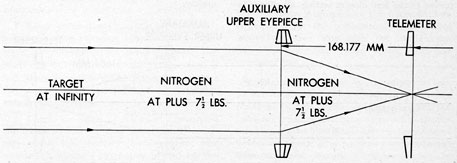
With the distance between the two lenses
thus adjusted in air, the introduction of nitrogen
at plus 7.5 psi lengthens the equivalent focal
length of the auxiliary upper eyepiece lens
exactly enough to cause its back focal point
Figure 4-63. Ray diagram of periscope showing action of 7 1/2 psi of nitrogen introduction.
234
Figure 4-64. Collimator reticle lens and objective lens ray diagram.
to lie on the plane surface of the telemeter lens.
Figure 4-63 shows the relative action created
by introduction of nitrogen at 7 1/2 psi.
Obviously, this adjustment should not be
made by moving the telemeter lens (for there
already has been made a 3/4 diopter adjustment
of the periscope eyepiece lens which is based
on maintaining a fixed position of the telemeter
lens, to compensate for the effect of the denser
nitrogen on focal lengths of lenses following
the telemeter); therefore, the only possible
adjustment is to move the auxiliary upper
eyepiece. Since the manufacturers of the periscope are aware of these facts, they have
designed the instrument so that only the ninth
reduced tube section (which carries the auxiliary
(upper eyepiece lens) is capable of adjustment.
It might be possible to move the auxiliary
upper eyepiece, 0.003 inch away from the
telemeter lens; however, since this distance is
small, it is much more accurate to measure
this distance optically (that is, by using a
target or object-distance at 1,200 feet) than
to measure it mechanically.
4V8. Basic principles of the Kollmorgen universal
collimator. The basic principles of the Kollmorgen universal collimator are described as
follows:
Since the introduction of nitrogen under
pressure necessitates collimating the periscope
on targets that are not at infinity, when the
lenses are in air (see target table under the
first function), and since targets at 4,800 feet,
3,110 feet, and even 1,200 feet are not possible
aboard a repair tender, the distance collimator
is used to reproduce these object-distances
optically.
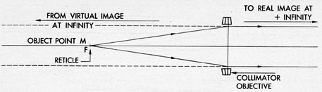
If the target of a collimator lies exactly in
the focal plane of the collimator objective lens,
the image is formed at infinity. In fact, we can
think of the lens as forming two images: a real
one (where the rays actually intersect) at plus
infinity, and a virtual image (where the rays
seem to come from) at minus infinity, as shown
in Figure 4-64.
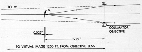
If the target is placed less than one focal
length away from the collimator objective,
the ray bundles diverging from each point
of the target have more divergence than the
converging lens is able to neutralize, and the
ray bundles emerging from the collimator lens
are still diverging slightly. For example, if the
equivalent focal length of the objective of the
collimator equals 481.7 mm = 19.27 in. and
if the target is moved 0.025 inch from the focal
plane toward the objective, a virtual image is
formed at a distance of 1,200 feet from the
collimator lens and on the same side of the lens
as the target (Figure 4-65). Thus, the rays from
each point of the target, after emerging from
the collimator lens, are still diverging at exactly
the same rate as though they had originated at
a real target 1,200 feet distant.
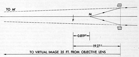
Taking another example, it is desired to
adjust the distance between target and collimator
objective so that the virtual image lies 35 feet
in front of the collimator lens (on the same
side as the target). If the collimator objective
lens has the same focal length as in the preceding
example, and if the target is moved 0.819 inch
from the focal plane toward the objective, the
image is virtual and is 35 feet from the collimator
objective, as indicated in Figure 4-66.
Thus it is seen that by suitably controlling
the distance between the target and the collimator
235
Figure 4-65. Collimator reticle lens set for 1200-foot target distance ray diagram.
Figure 4-66. Collimator reticle lens set for 35-foot target distance ray diagram.
objective, it is possible within a limited
space to obtain optical target at any distance
desired from zero feet to infinity. The former
could be obtained if the target were placed in
contact with the collimator objective, and
the latter if the target were placed in the focal
plane of the collimator objective lens.
This, however, is only one of the three main
functions of the Kollmorgen universal collimator.
The three functions are as follows:
1. It is an optical means of producing distant
targets in a limited space for shipboard use, as
outlined above. The distances that are necessary
for the different types of periscopes (to compensate for the introduction of nitrogen under
pressure) are:
a. Type II (5 telescope systems) (1.414)
lp hp
35 ft 1,200 ft
b. Type III (3 telescope systems) (1.99)
lp hp
47 ft 3,110 ft
c. Type IV (3 telescope systems) (night use)
lp hp
62 ft 4,800 ft
If the collimator objective lens has an equivalent focal length of 481.7 mm (= 19.268 in.),
in order to place the virtual target at the desired
distances listed in the foregoing table, it is necessary to move the actual target from the focal
plane of the collimator objective toward the
objective lens by the amounts shown in the
table on page 237.
It must be remembered that the figures in
this table apply only when the collimator
objective lens has an equivalent focal length
236
Virtual Target Distance (in feet)
Range Table Actual Target Movement (in inches)
Actual Micrometer Turns
Infinity
0.0000
0
5,000
0.0060
6 graduations
4,800
0.0063
6 graduations
3,110
0.010
10 graduations
1,200
0.025
25 graduations
62
0.471
15 turns, 3 graduations
47
0.617
19 turns, 24 graduations
35
0.819
26 turns, 7 graduations
equal to the above value. Since the factory
tolerance of lenses for this collimator is held
to plus or minus 1 percent of the specified focal
length, no sensible variation results.
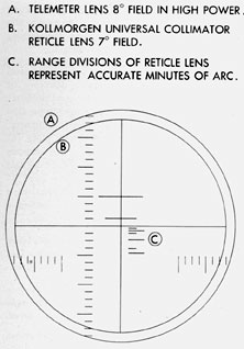
2. The Universal collimator is an optical
means for checking accurate displacement of
the lower (split) objective lens halves with
calibrated range dials of the stadimeter at a
known height on a graduated reticle lens set
at infinity.
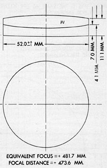
It consists of a graduated reticle lens used
with a collimator objective lens of effective
focal length of exactly 481.7 mm (Figure
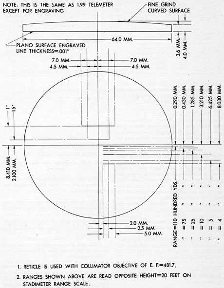
4-67). The reticle lens (Figure 4-68) is provided
with etched vertical and horizontal lines forming
a crossline. The lower right quarter of the
reticle has six etched graduated lines, each line
being of alternate height to distinguish it
clearly. The graduated lines are etched on the
plano-surface of the reticle, while the curved
surface is fine ground. The reticle, being in the
focal plane of objective lens, produces parallel
light, thereby forming an infinity target.
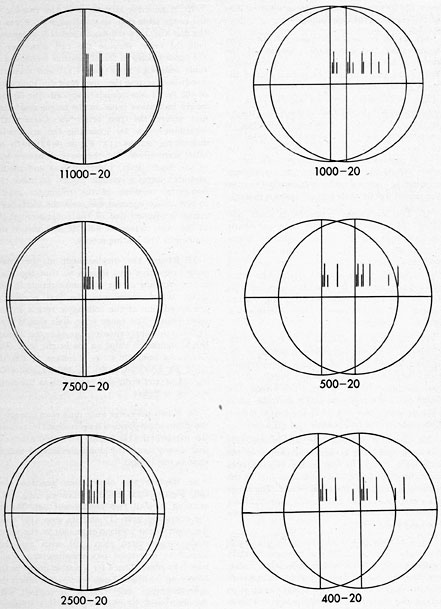
The reticle lines (Figure 4-68) are spaced
consecutively in the following manner: All
six graduated lines are located 2.0 mm from the
vertical line of the crossline.
a. The first graduated line of 2.5 mm length
is located 0.290 nun from the horizontal line
of the crossline.
b. The second graduated line of 5.0 mm length
is located 0.430 mm from the horizontal line
of the crossline.
c. The third graduated line of 2.5 mm length
is located 1.285 mm from the horizontal line
of the crossline.
d. The fourth graduated line of 5.0 mm
length is located 3.210 mm from the horizontal
line of the crossline.
e. The fifth graduated line of 2.5 mm length
is located 6.425 mm from the horizontal line
of the crossline.
f. The sixth graduated line of 5.0 mm length
is located 8.030 mm from the horizontal line
of the crossline.
The angle formed by the distance between
the first graduation and the horizontal line of
crossline forms the base relative to effective
focal length of objective lens hypotenuse, and
is found by dividing:
1) 0.290 mm by 481.7 mm which equals
0.0062 radians or 2 minutes 4 seconds of arc.
The angles of the other five graduated lines
are found in similar manner:
2) 0.430/481.7 = 0.00088 radians or 3' 4" of arc
3) 1.285/481.7 = 0.00266 radians or 9' 10" of arc
4) 3.210/481.7 - 0.00666 radians or 22' 55" of arc
5) 6.425/481.7 = 0.01333 radians or 45' 51" of arc
6) 8.030/481.7 = 0.01666 radians or 57' 18" of arc
The above angles correspond to a target
angle of 20-foot height at the following ranges:
1) 11,000 yards
4) 1,000 yards
2) 7,500 yards
5) 500 yards
3) 2,500 yards
6) 400 yards
3. As its third function, the Universal collimator provides a means of checking the vertical
displacement of the line of sight in changing
from high to low power. Two graduations
which intersect the vertical line are incorporated
in the upper half of the reticle. These provide
accurate graduations in degrees for checking
this displacement. Both graduations are placed
in the reticle as follows:
a. The large graduation intersects the vertical
line, and is located 8.410 mm from the horizontal
crossline. This distance represents 1 degree of arc in
high power or 4 degree in low power. This line extends
on each side of the vertical crossline a distance
of 7.0 mm.
b. The small graduation intersects the vertical
line, and is located 2.100 mm from the horizontal
crossline. This distance represents 15' of arc
in high power or 1 degree in low power. This line
extends on each side of the vertical crossline
a distance of 4.5 mm.
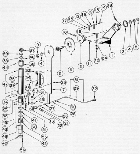
4V9. Description of the Sperry-Kollmorgen collimator. The Sperry-Kollmorgen collimator consists of the Sperry attachments which hold
the Kollmorgen universal collimator. Figure
4-69 shows the Sperry-Kollmorgen collimator.
All bubble numbers in Section 4V9 refer to
Figure 4-69 unless otherwise specified.
Ill. No.
Drawing Number
Num- ber Re- quired
Nomenclature
1
P-1641-1
1
Collimator base plate bracket
2
P-1641-2
1
Height adjusting bearing
3
P-1641-3
1
Height adjusting bearing lock ring
4
P-1641-4
2
Collimator base plate shaft lock nut washers
5
P-1641-5
1
Collimator base plate shaft
6
P-1641-6
1
Azimuth disk plate
7
P-1642-1
1
Collimator base plate
8
P-1642-2
2
Collimator base plate shaft, outer lock nuts
9
P-1642-3
1
Collimator base plate shaft, inner lock nut
10
P-1642-4
1
Wedge lock
11
P-1642-5
1
Wedge lock bolt
12
P-1642-6
2
Azimuth disk plate clamp arms
13
P-1642-8
1
Reticle light shield
14
P-1642-10
1
Wing nut stud
15
P-1642-11
2
Azimuth disk plate outer clamp arm washers
16
P-1642-12
1
Azimuth disk plate clamp arm spacer washer
17
P-1642-14
1
Azimuth disk plate clamp arm wing nut
18
P-1642-15
1
Collimator tube bracket height adjusting cap screw
19
P-1642-16
4
Collimator base plate bracket and optical bench bracket cap screws
20
P-1642-17
4
Collimator base plate bracket and optical bench bracket cap screw nuts
21
P-1642-18
2
Reticle light shield lockscrews
22
P-1642-19
2
Filter mount lockscrews
23
P-1642-20
4
Collimator tube bracket cap screw
24
P-1642-20
4
Collimator base plate bracket and optical bench bracket cap screw washers
25
P-1642-21
4
Collimator tube bracket clamp screws
26
P-1642-22
1
Candelabra mazda bulb
27
P-1642-23
1
Keyless socket
28
P-1642-24
1
Brass tubing section
29
P-1642-25
1
Feed-thru cord switch
30
P-1642-26
1
Finger grip plug cap
31
P-1642-27
1
Rubber covered wire cord
32
P-1642-27A
1
Wire cord plug
33
P-1643-1
1
Collimator tube bracket
34
P-1643-2
2
Collimator tube bracket clamps
35
P-1643-3
1
Collimator tube thrust collar
36
P-1644-1
1
Objective lens mount end bushing
239
Ill. No.
Drawing Number
Num- ber Re- quired
Nomenclature
37
P-1644-2
1
Objective lens mount
38
P-1644-3
1
Objective lens clamp ring
39
P-1644-4
1
Collimator tube
40
P-1644-5
1
Reticle lens mount retaining ring
41
P-1644-6
1
Reticle lens clamp ring
42
P-1644-7
1
Reticle lens mount
43
P-1644-8
1
Reticle lens mount axial alignment key
44
P-1644-9
1
Objective lens mount lockscrew
45
P-1644-10
1
Reticle lens mount alignment key lockscrew
46
P-1644-11
1
Objective lens clamp ring lockscrew
47
P-1644-12
2
Collimator tube and reticle lens mount end bushing also objective lens mount end bushing lockscrews
48
P-1644-13
1
Reticle lens clamp ring lockscrew
49
P-1645-1
1
Filter mount
50
P-1645-2
1
Filter clamp ring
51
P-1645-3
1
Reticle lens mount lock ring
52
P-1645-4
1
Reticle lens mount end bushing
53
P-1645-5
1
Reticle lens mount actuating sleeve
54
P-1645-6
1
Name plate
55
P-1645-7
2
Name plate lockscrews
56
P-1645-8
6
Reticle lens mount retaining ring lockscrews
57
P-1645-9
1
Micrometer vernier arm
58
P-1645-9A
4
Micrometer vernier, arm lockscrews
59
P-1646-1
1
Objective lens
60
P-1646-2
1
Reticle lens
61
P-1646-3
1
Filter, Corning sextant green
a. Collimator base plate bracket. The
collimator base plate bracket (1) is made of
cast bronze. It has a large rectangular base
flange with two supporting webs below the base
flange. The base flange is attached to a welded
plate at the end of the optical I-beam bench
with four cap screws (19), washers (24), and
nuts (20). The four holes in the base flange are
elongated, thus allowing for the adjustment of
the bracket during the alignment of the Sperry-Kollmorgen collimator to the optical I-beam
bench.
The rectangular base flange has a projecting
arm, which has a 45 degrees inclination. The width
of the arm tapers toward the large swivel hub
section which is carried at an appropriate center
distance for the height adjusting bearing (2).
This hub section is bored to carry the height
adjusting bearing, and has a projecting lug
section on the periphery. The lug section is
split in the inclined centerline. One lug has a
tapped hole, while the other has a clearance hole
for a cap screw (18). The cap screw when
tightened secures the height adjusting bearing
(2) at the desired inner tube or outer tube
centerline required for the periscope being
repaired.
The wall thickness of the projecting arm is
uniform, except for a supporting web in the
center extending upward to the hub section
from the base flange, located on the outer side
following the pattern of projecting arm inclination. The hub section extends outward 1 inch
from the outer wall of the projecting arm.
The collimator base plate bracket holds the
complete collimator attachment with provision
for swinging the collimator base plate (7) through
elevation of 95 degrees and depression of 25 degrees as noted
by the graduations on the azimuth disk plate
(6).
A tapped hole is provided in the wall of the
projecting arm at an appropriate center distance
below the center axis of the hub section for the
azimuth disk plate wing nut stud (14). The stud
carries the washer (15) next to the inner projecting arm wall, two azimuth disk plate clamp
arms (12) separated with a spacer washer (16),
and another washer (15) backed up by the
wing nut (17).
b. Height adjusting bearing. The height
adjusting bearing (2) is made of brass and is
3 3/16 inches in length. It is cylindrical and is
blued. It has a large narrow shoulder flange
with an undercut shoulder a sliding fit in the bore
of the collimator base plate bracket (1) projecting arm hub section. Outward from this
undercut shoulder section, a thread relief and a
threaded periphery to carry a height adjusting
bearing lock ring (3) are provided. A small
undercut shoulder section is provided on the
outer part of the threaded periphery.
The height adjusting bearing is provided with
an offset 1 1/2-inch diameter hole running through
240
Figure 4-69. Sperry-Kollmorgen collimator.
its length. It is offset with its centerline 1 inch
from the center axis to carry the collimator
base plate shaft (5). A perpendicular hole of
1 1/16-inch diameter is provided in the small
undercut shoulder section having a counterbored section of 2 7/16 inches in depth to carry
the wedge lock (10) and the wedge lock bolt
(11). The centerline of this clearance hole and
counterbored section is eccentric and is offset
from the center axis 0.156 inch. The entrance
of the clearance hole is spot faced to offer a
flat surface to the shoulder of the wedge lock
bolt (11).
The large hole carrying the collimator base
plate shaft (5) permits a variance of eccentricity
to the height adjusting bearing, and is secured
temporarily with the lock ring (3) upon its
241
contact with the collimator base plate bracket
projecting arm hub section (1), and is maintained
by the split hub section by securing the adjusting
cap screw (18). The wedge lock (10), having a
concave radius that conforms to the contour of
the collimator base plate shaft (5), is secured by
tightening the wedge lock bolt (11). The concave
radius of the wedge lock (10) upon the thrust
created by tightening of the wedge lock bolt
(11) secures the collimator base plate (7) at any
desired degree of azimuth.
c. Height adjusting bearing lock ring. The
height adjusting bearing lock ring (3) is made
of 1/4-inch thick brass and is cylindrical. The
periphery is medium diamond knurled, with the
bore threaded a free turning fit when engaged on
the threaded periphery of the height adjusting
bearing (2). The lock ring serves to carry the
height adjusting bearing (2) snugly against the
inner surface of the hub section of the collimator
base plate bracket projecting arm (1).
d. Azimuth disk plate. The azimuth disk
plate (6) is made of 1/4-inch brass plate having
a diameter of 9 inches. The center axis of the
plate is bored a sliding fit on the large shoulder
flange of the collimator base plate shaft (5).
The projecting shoulder of 1/64-inch width
allows sufficient free movement of the disk
plate when in close contact with the collimator
base plate (7) and the shoulder flange face of the
height adjusting bearing (2). The projecting
shoulder is provided on the inner face and is
3 7/8 inches in diameter.
The inner face of the plate is graduated in
degrees covering 120 degrees. Each degree marking
between the interval of 5 degrees is 3/16 inch in length,
starting on a diameter of 8 inches. Every fifth
degree interval is 1/4 inch in length. Starting
with the sixth interval from the right, the 0
numeral is engraved. Each 10-degree interval
is engraved additive to and including the 90 degrees
for elevation. The same pattern is followed for
the 10-degree intervals in depression.
The azimuth disk plate is secured with the
two azimuth disk plate clamp arms (12). Each
arm has a piece of green beige glued to its inner
contact face, which secures the plate by the
tightening of the wing nut (17).
e. Collimator base plate shaft. The collimator base plate shaft (5) is made of plain carbon
steel and is 6 1/4 inches in length. It is provided
with a large diameter narrow shoulder flange
which serves as a bearing for the bored axis
hole in the azimuth disk plate (6).
The square shoulder section carries the square
broached hole in the collimator base plate. (7).
The square shoulder section has an undercut
shoulder on its outer face to carry a lock nut
washer (4). The small undercut stub section
has the periphery threaded to carry the hexagon
lock nut (9) to secure the collimator base plate
(7) tight against the large shoulder flange
section.
The thickness of the large narrow shoulder
flange is sufficient to allow the azimuth disk
plate (6) a snug sliding clearance between the
attached collimator base plate (7) rear face and
the face of the large shoulder flange of the height
adjusting bearing (2).
The main body section is a sliding fit in the
large offset hole in the height adjusting bearing
(2), and retains the collimator base plate
(7) at the desired degree of azimuth by means
of a wedge lock (10) clamped snugly by the
wedge lock bolt (11). The outer part is provided
with a threaded periphery to carry a locknut
washer (4) and two hexagon locknuts (8). The
washer rests against the outer face of the height
adjusting bearing (2) and the shaft is secured by
the two hexagon locknuts (8).
f. Wedge lock and wedge lock bolt. 1.
Wedge lock. The wedge lock (10) is made of
plain carbon steel and is 2 1/8 inches in length.
The outside diameter is a sliding fit in the eccentric counterbored section in the narrow shoulder
section hole in the height adjusting bearing (2).
It has a concave radius located 1 1/2 inches from
the solid end face. The concave radius conforms
to the contour of the collimator base plate
shaft main body (5).
The center axis has a tapped hole to receive
the threaded section of the wedge lock bolt (11).
The tightening of the wedge lock bolt shoulder
against the spot face in the height adjusting
bearing narrow shoulder (2) causes the concave
radius to secure the main body of the collimator
base plate shaft (5), thus maintaining the collimator base plate (7) in the desired azimuth
setting.
242
2. Wedge lock bolt. The wedge lock bolt
(11) is made of plain carbon steel and is 2 3/4
inches in length. The long threaded stem section
engages in the tapped hole axis in the wedge lock
(10). The shoulder section serves as a support
on the flat spot face in the small shoulder of the
height adjusting bearing (2). The tightening
of the bolt causes the wedge lock to grip the
collimator base plate shaft (5), thus restricting
it from rotation. The stub section is square for
the attachment of a wrench.
g. Azimuth disk plate clamp arms. The
two azimuth disk plate clamp arms (12) are
made of 1/8-inch brass and are 3 inches in length.
Both are provided with elongated slots to allow
them to slide axially away from the azimuth
disk plate (6). The inner face of each pointed
clamp arm is provided with a piece of glued
green beige for clamping of the azimuth disk
plate (6) and the prevention of scratches to it
while clamping. The clamp arms are carried
on the projecting wing nut stud (14). The inner
clamp arm rests against a washer (15) and is
separated from the outer clamp arm with a
spacer washer (16). The securement of both arms
is accomplished by the tightening of a wing
nut (17) on the outer washer (15).
h. Collimator base plate. The collimator
base plate (7) is made of 3/8-inch steel plate
and is 35 inches in length. The axial section
is provided with a square broached hole, a
sliding fit over the square section shoulder
of the collimator base plate shaft (5), and is
secured to it by the locknut washer (4) and
locknut (9).
The axial section is 8 inches in diameter and
forms a concave junction on opposite sides of
the centerline with the arm 4 5/8 inches wide.
The arm is uniform in width from the concave
junctions in a distance of 21 1/4 inches. Beyond
this point the arm forms a concave junction on
opposite sides with a handle 1 1/2 inches in width
and 6 3/4 inches in length.
The axial section is beveled at 30 degrees covering a
60 degree minor chord area with an engraved line intersecting its centerline. The engraved line serves
as an index line to designate the position of the
collimator in azimuth when in coincidence with
the graduations of the azimuth disk plate (6).
The collimator tube bracket (33) is mounted
in the centerline of the arm and axial section,
and is located with its perpendicular centerline
14 7/8 inches from the axis of the axial section, to
carry the Kollmorgen universal collimator.
The collimator tube bracket is secured to the
arm with four cap screws (23). These cap screws
are inserted into clearance holes in the arm and
screw into tapped holes in the collimator tube
bracket (33).
The outer 1-inch part of the handle section
is undercut to carry the reticle light shield (13)
secured on opposite side with two lockscrews
(21). A 1/8-inch pipe tapped hole is provided
near the end of the handle to receive a brass
tubing section (28). It carries the keyless
socket (27), and a candelabra mazda bulb (26).
i. Collimator tube bracket, thrust collar,
and tube. 1. Collimator tube bracket.
The collimator tube bracket (33) is made of
cast bronze and is rectangular shaped. Its width
conforms to the width of the collimator base
plate (7) arm section, and the length is sufficient
to carry the collimator tube (39).
The base of the bracket is provided with a
1 1/2-inch raised boss section on each end the
entire width, with a cored section connecting
the raised boss sections. These sections are
secured to the arm section of the collimator
base plate (7) with four cap screws (23) which
are inserted into clearance holes in the base plate
and screwed into tapped holes in the raised boss
sections to secure the bracket to the base
plate.
The bracket is provided with end walls which
are reinforced with 45 degrees angle webs from the main
body, and has a center web connecting each end
wall. A semicircular clamp (34) is fitted on each
end wall upper lace and secured with two
Allen head cap screws (25) each. The cap screws
are inserted into clearance holes in the clamps
(34) and screwed into tapped holes in the end
walls. The end walls and the clamps are bored
together, to carry the collimator tube (39)
A rectangular name plate (54) is secured to
the main body with two lockscrews (55).
2. Collimator tube thrust collar. The
collimator tube thrust collar (35) is made of
brass and is cylindrical. It has an outside
243
diameter of 3 7/16 inches, with the axis bored.
The bored diameter is tinned and soldered to
the outer diameter of the collimator tube (39)
to retain it axially as it lies in a vertical plane.
The external surface of the thrust collar has a
concave radius, with the sharp corners rounded
off. The thrust collar rests against the outer wall
of the collimator tube bracket (33) facing toward
the axial section of the collimator base plate (7).
3. Collimator tube. The collimator tube
(39) is made of brass and is 15 inches in length.
The external surface is uniform its entire length
with the bore having a nominal wall thickness.
The bore is provided with blued anti-reflection
threads.
The opposite ends of the tube are provided
with threaded counterbored sections of equal
depth. One end carries the threaded periphery
section of the objective lens mount end bushing
(36) secured with a lockscrew (47), while the
opposite end carries the threaded periphery
section of the reticle lens mount end bushing
(52) secured with a lockscrew (47).
j. Objective lens mount end bushing, lens
mount, lens, and clamp ring.1. Objective
lens mount end bushing. The objective
lens mount end bushing (36) is made of brass
and is 3 inches in length. The large external
diameter conforms to the diameter of the
collimator tube (39). The undercut section is
threaded to engage in the threaded counterbored
section in the collimator tube and is secured
with a lockscrew (47).
The inner surface is bored for light transmission and threaded for anti-reflection. Its
outer part is counterbored and threaded a
sufficient depth to carry the threaded periphery
objective lens mount (37). The threaded counterbored section is of sufficient depth to allow
axial movement of the objective lens mount
(37) for collimation of the collimator. The
mount is secured with a lockscrew (44) after
collimation. This lockscrew is screwed into a
tapped hole in the objective lens mount end
bushing wall (36) and extends into the spotted
face in the threaded periphery of the mount.
2. Objective lens mount. The objective
lens mount (37) is made of brass and is 3/4 inch
in length. The periphery is threaded and screws
freely in the threaded counterbored section
in the objective lens mount end bushing (36).
It is bored for light transmission and has two
counterbored sections. The small counterbored
section carries the periphery of the objective
lens (59) against a narrow shoulder seat. The
large counterbored section is threaded and
carries the clamping (38) threaded periphery
for securing the objective lens (59) snugly, and
is secured with a lockscrew (46). The lockscrew
is screwed into a tapped hole in the mount and
extends into the partially tapped hole in the
clamp ring. The outer face of the mount is
chamfered at 60 degrees from its bore, leaving a shoulder
seat wall of 1/16 inch.
3. Objective lens. The objective lens (59)
is made of two optical elements, consisting of
a double convex crown element cemented to a
divergent meniscus flint element, forming a
positive doublet. It is mounted in the objective
lens mount (37) with the crown element resting
against the seat of the mount. It is secured
snugly with a clamp ring (38) and a lockscrew
(46, Figure 4-67 shows this lens in detail).
4. Objective lens clamp ring. The objective
lens clamp ring (38) is made of brass and is of
nominal thickness and width. The periphery
is threaded to screw into the threaded counterbored section in the objective lens mount (37) to
secure the objective lens (59). The clamp ring
is chamfered at 15 degrees from its bore, and is provided
with opposite slots in the narrow side face for
the insertion of a special wrench. The clamp ring
As secured with a lockscrew (46) which extends
inward from a tapped hole in the objective lens
mount (37) into the partially tapped hole in
the clamp ring.
k. Reticle lens mount end bushing,
mount, lens, and clamp ring. 1. Reticle
lens mount end bushing. The reticle lens
mount end bushing (52) is made of brass and
is 4 13/16 inches in length. The external surface
is provided with a large shoulder section of 1 1/2
inches to accommodate sufficient wall thickness
for the internal counterbored section. The
medium shoulder section diameter conforms
to the diameter of the collimator tube (39),
while the small undercut shoulder is threaded
to engage into the outer end of the collimator
tube threaded counterbored section, and is
244
secured with a lockscrew (47). The lockscrew is
screwed into a tapped hole in the collimator
tube (39) and extends into a spotted recess
in the threaded periphery of the end bushing.
The end bushing is bored for light transmission
and is threaded for anti-reflection. It is provided
with two counterbored sections; the smaller of
the two has a depth of 3.875 inches and carries
the reticle lens mount (42) of an axial sliding
fit. The large counterbored section is threaded
and has sufficient depth to accommodate the
axial movement of the reticle lens mount
actuating sleeve threaded periphery (53).
The medium shoulder is provided with an
axial slot in a 1 1/16-inch distance. The axial
slot serves as a guide for the axial alignment
key (43) attached to the reticle lens mount
(42). The periphery of the medium shoulder
section is engraved at intervals for the various
target distances of the present three types of
periscopes used in the submarine service,
starting from the infinity engraved graduation.
These graduations are determined after assembly
by calculation and known target distances.
The engraved index line on the axial alignment
key (43) designates the position of the reticle
lens (60).
A micrometer vernier arm (57) is secured
on the large shoulder periphery with four
lockscews (58) and furnishes the repairman
an accurate determination as to the calculated
distance the reticle lens mount is moved inward
axially for each distance determination.
2. Reticle lens mount. The reticle lens.
mount (42) is made of brass and is 4 9/16 inches
in length. It is cylindrical, and is provided with
a narrow shoulder flange in the outer part.
The external diameter is a sliding fit in the small
counterbored section in the reticle lens mount
end bushing (52) and is carried axially by the
reticle lens mount actuating sleeve (53) with
its attached axial alignment key (43).
The external diameter is undercut a distance
of 2.125 inches to its narrow shoulder flange,
thus allowing a nominal bearing surface for the
reticle lens mount actuating sleeve (53). The
narrow shoulder flange fits into the counterbored
section in the reticle lens mount actuating
sleeve, and is carried outward axially by means
of this narrow shoulder flange, and inward by
the attached retaining ring (40) secured on the
outer side face of the reticle lens mount actuating
sleeve.
The mount is bored for light transmission
and is threaded for anti-reflection. The inner
end has two counterbored sections. The smaller
serves as a seat for the reticle lens (60), while
the larger is threaded to carry the clamp ring
(41) snugly against the reticle lens, and is
secured with a lockscrew (48).
3. Reticle lens. The reticle lens (60) is a
plano-convex crown element. The convex surface is fine round, and faces the seat of the
reticle lens mount (42). It is secured snugly
in the seat of the mount with the clamp ring
(41) secured with a lockscrew (48). The plano
surface of the lens is engraved, and is described
under Section 4V8 and 2nd function. Figure
4-68 shows the detailed calibrations of this lens.
4. Reticle lens clamp ring. The reticle
lens clamp ring (41) is made of brass and is of
nominal thickness and width. The periphery is
threaded to screw into the threaded counterbored
section in the reticle lens mount (42) to secure
the lens. It is bored for light transmission, and
has a counterbored section threaded for anti-reflection. The counterbored section leaves a
narrow flat shoulder to contact the plano-surface of the reticle lens (60). The narrow side
face is provided with two opposite slots for the
insertion of a special wrench. The clamp ring
tightens the reticle lens snugly and is secured
with a lockscrew (48). The lockscrew is screwed
into a tapped hole in the reticle lens mount
(42) and extends into a partially tapped hole
in the clamp ring.
1. Reticle lens mount axial alignment
key. The reticle lens mount axial alignment
key (43) is made of corrosion-resisting steel
and is 0.406 inch in length. It is a sliding fit in
the axial slot in the reticle lens mount end
bushing (52) and is secured to the reticle lens
mount bearing shoulder periphery in the axial
slot with a lockscrew (45). The lockscrew is
inserted into a countersunk clearance hole
located 1/8 inch from its end, and is screwed into
a tapped hole in the mount. Both ends of the
key have a convex radius to conform to the
concave radius ends of the axial slot. An
245
engraved index line is provided 5/32 inch from
the solid end to provide the repairman with a
reference line designating the position of the
reticle lens on either the distance target or the
infinity target. The key is carried axially with
the reticle lens mount (42) in the axial slot of
the reticle lens mount end bushing for an
approximate distance of 0.875 inch. This distance
is sufficient for the various distance targets of
low- and high-power magnification required
by the three types of periscopes used in the
submarine service.
m. Reticle lens mount actuating sleeve.
The reticle lens mount actuating sleeve (53) is
made of brass and is 1 15/16 inches in length. It
is provided with a large shoulder flange, having
its periphery medium diamond knurled. The
undercut section is threaded its entire length
with 32 threads per inch to carry a lock ring
(51) and engages into the threaded counterbored
section in the reticle lens mount end bushing
(52). It is bored to carry the reticle lens mount
(42), a sliding fit with a counterbored section in
its large shoulder flange. This counterbored
section serves as a thrust stop to carry the reticle
lens mount (42) axially in the reticle lens mount
end bushing (52). The outer face of the large
shoulder flange is provided with a retaining
ring (40) secured with six lockscrews (56).
This retaining ring serves as a thrust ring to
carry the reticle lens mount (42) axially into
the reticle lens mount end bushing (52). The
six lockscrews (56) are inserted in countersunk
Figure 4-70. Collimator micrometer vernier arm.
clearance holes in the retaining ring (40) and
screwed into tapped holes in the reticle lens
mount actuating sleeve (53).
n. Reticle lens mount lock ring and retaining ring. 1. Reticle lens mount lock
ring. The reticle lens mount lock ring (51)
is made of brass and is of nominal thickness and
width. Its periphery conforms to the periphery
of the reticle lens mount actuating sleeve (53)
large shoulder flange, and is knurled in the same
manner. The bore is threaded and screws on the
actuating sleeve threaded periphery. The lock
ring, when screwed up against the shoulder of
the reticle lens mount end bushing (52), secures
the actuating sleeve from further movement,
thus locking it in place.
2. Reticle lens mount retaining ring.
The reticle lens mount retaining ring (40)
is made of 1/16-inch brass. It is cylindrical,
with the outer and inner diameter conforming
to the large shoulder flange inner and outer
diameters. The retaining ring is provided with
six equally spaced countersunk holes for lockscrews (56). The lockscrews are inserted into
the countersunk clearance holes in the retaining
ring and screwed in tapped holes in the large
shoulder flange of the reticle lens mount actuating sleeve (53). The retaining ring serves as a
thrust ring to carry the reticle lens mount (42)
axially into the reticle lens mount end bushing
(52) with the movement of the actuating
sleeve (53).
o. Micrometer vernier arm. The micrometer vernier arm (57) is made of brass and is
3 inches in length. It has a rectangular base
section with a narrow vernier arm section. The
inner circumference of the rectangular base
section follows the contour of the reticle lens
mount end bushing large periphery and has a
nominal wall thickness. Figure 4-70 shows an
enlargement of this vernier arm for fleet
adaptation.
The inner circumference of the narrow vernier
arm section is stepped upward with a chamfer
allowing clearance over the periphery of the lock
ring (51) and the shoulder flange of the reticle
lens mount actuating sleeve (53). The vernier
arm is beveled at approximately 20 degrees, and is
engraved in 1/32-inch intervals, having a total
246
of 28 intervals in a distance of 7/8 inch. At intervals of 1/8 inch, a numeral starting with 0
is engraved along the graduations, representing
each fourth 32nd. The numerals are additive
by 4 for each additional numeral up to and
including 28. The vernier arm is engraved
in 1/32 inch to correspond with 32 threads per
inch on the internal threaded section in the
reticle lens mount end bushing (52) and the
threaded periphery of the reticle lens mount
actuating sleeve (53).
Each revolution of the reticle lens mount
actuating sleeve (53) represents 1/32-inch axial
movement of the reticle lens (60) and mount
(42). The knurled periphery of the reticle lens
actuating sleeve shoulder flange is undercut a
distance of 9/64 inch from the inner shoulder
face. This provides a smooth surface for the
engraving of micrometer graduations and numerals. This undercut periphery has 31 equal
graduations which represent a fraction over
one-thousandth inch between each graduation.
Starting with 0 as the infinity numeral, every
fifth graduation is additive by 5 for each additional numeral up to and including 30. The 31
graduations on the undercut periphery represent
0.03125 thousandths inch or 1/32 inch upon
one complete revolution of the reticle lens
mount actuating sleeve shoulder face from the 0
graduation until it again reads 0 next to the
vernier arm. The vernier graduations designate
the number of turns or 1/32 inch the reticle
lens (60) and mount (42) are moved, axially
from the 0, or infinity, setting of the Kollmorgen
universal collimator. The lock ring (51) is
secured each time snugly against the face of the
reticle lens mount actuating sleeve (53). The
securement of the lock ring starting at infinity
removes the lost motion in the threads, and
places an outward thrust on the reticle lens
mount actuating sleeve at each locked setting.
The vernier arm rectangular base is secured to
the reticle lens mount end bushing (52) periphery
perpendicular to the axial slot on the light side.
The four tapped holes are spotted from the
clearance holes in the rectangular base after
the Kollmorgen universal collimator is collimated
at infinity by using a Quartermaster glass of
16-power or a transit of 24-power magnification
set for sharp definition. The lock ring (51) is
secured snugly against the outer face of the
reticle lens mount end bushing (52).
Secure the micrometer vernier arm to the
periphery of the reticle lens mount end bushing
(52) with four lockscrews (58). These lockscrews
are inserted in countersunk clearance holes
in the rectangular base and screwed into tapped
holes in the reticle lens mount end bushing (52).
p. Reticle light shield. The reticle light
shield (13) is made of brass tubing and is 5 inches
in length. The lower part of the shield has two
opposite 1/2-inch wide lugs for attachment to
the outer handle section of the collimator
base plate (7) and is secured with two lockscrews
(21). The upper end of the shield has a soldered
cap to confine the illuminated light rays to the
perpendicular exit of the shield.
The shield setting on the side face of the
collimator base plate (7) has a short piece
of brass tubing soldered to it, forming a spud
joint. Two screws (22) are located on opposite
sides of this junction section projecting inward
to carry the filter mount (49). The shield covers
the candelabra mazda bulb (26) screwed in
the keyless socket (27).
q. Filter mount. The filter mount (49)
is made of brass and is 25/32 inch in length.
It consists of a large narrow shoulder and an
undercut medium shoulder. The long undercut
shoulder of 1/2-inch length is a sliding fit with
the junction brass tubing section of the reticle
light shield (13) and engages with the two
opposite projecting screws (22).
The mount is bored for filtered light illumination, and is counterbored to carry the filter (61)
of Corning sextant green. The outer part of the
counterbored section is threaded to carry
the filter clamp ring (50).
The narrow undercut shoulder carries a
cylindrical disk 1/16 inch wide and 3 17/32 inches
in diameter, which is soldered to the narrow
shoulder. The large diameter of the cylindrical
disk serves as a shield to prevent stray light
other than the illuminated light from illuminating the reticle lens (60).
The long undercut shoulder section is provided with two bayonet slots to secure the
mount in the shield junction upon their engagement with the inward projecting screws (22).
247
r. Feed-thru cord switch. The feed-thru
cord switch (29) is connected between two
pieces of rubber covered cord (31). One end of
the rubber covered cord connects to a wire
cord plug (32), while the other end passes.
through a finger grip plug cap (30), and a brass
tubing section (28) that is attached to the keyless socket (27).
The feed-thru cord switch is an a.c. or d.c.
switch having an OFF and ON switch lever.
s. Collimation. 1. The Kollmorgen universal
collimator is collimated at infinity with the
reticle lens mount axial alignment key (43)
near the outer end of the axial slot of the reticle
lens mount end bushing (52). The transit is
focused on an infinity distant target of 2,000
yards or better, free of any detection of parallax.
The transit is transported with this setting for
adjustment of the collimator at the transit
infinity setting. Remove the lockscrew (44)
and turn the objective lens mount axially
until observations indicate that no parallax
is apparent on the reticle lens crossline. Insert
and secure the lockscrew (44) after collimation,
placing a new spotted face in the objective
lens mount threaded periphery (37).
2. A suitable method to be followed on a
repair tender is to place a Quartermaster glass
of 16-power magnification (with the eyepiece
set at 0 diopter), followed with a 3-power
magnification auxiliary telescope (with the
eyepiece set for the observer's eye) to check
the collimator infinity setting.
The auxiliary telescope is focused from plus
diopter to the observer's diopter reading, to
ascertain that the reticle crossline and diopter
readings are in sharp definition. At this reading
there should be no parallax apparent on the
reticle lens crossline. A series of observations to
determine the correct setting of the objective
lens (59) should be taken.
All ranges in feet below the infinity target are
calculated in thousandths-inch as per actual
target movement table. Refer to Section 4V8,
first function.
The Quartermaster glass used should be in
collimation.
4V10. Alignment of the Sperry-Kollmorgen collimator to the optical I-beam bench. This procedure
is performed in the following manner (all
bubble numbers in this section refer to Figure
4-69 unless otherwise specified)
a. General. The Sperry-Kollmorgen collimator is swung through azimuth for checking
the elevation and depression angles of the head
prism. Since the altiscope mechanism elevates
and depresses the line of sight of the periscope
without change in azimuth of more than 10
minutes of arc, between an elevation of 10 degrees
and depression of 10 degrees of the line of sight, it
must be properly aligned to the perpendicular
and horizontal plane of the optical I-beam
bench. Check the reticle lens mount actuating
sleeve (53) to ascertain that its 0 micrometer
graduation is located at the 0 graduation as
indicated by the micrometer vernier arm (57,
Figure 4-71).
It is used with the periscope lying in a horizontal plane in V-blocks on the optical I-beam
bench having a true parallel plane. The observer
views the collimator reticle lens looking downward into the eyepiece end of the periscope.
The Sperry-Kollmorgen collimator used travels
in a vertical plane.
b. Alignment. The Sperry-Kollmorgen collimator is aligned to the optical I-beam bench in
the following manner:
1. Place the boresight disk of 6.495-inch
diameter in the V-block of the optical I-beam
bench (Figure 4-72). Secure the boresight disk
by turning the adjusting knobs of the V-block
attached clamp bracket. These clamp the disk
tight in the V-blocks.
2. Insert the boresight telescope, screwing
the threaded periphery into the internal threaded
axis of the boresight disk. The telescope adjusting screws are to be set truly horizontal and
vertical. Tighten the knurled lock ring of the
boresight telescope against the disk (Figure
4-72).
3. Place the crossline disk of 6.495-inch
diameter in the V-block located at the far end
and on the optical I-beam bench.
4. Focus the telescope on the grooved-crossline disk until the crossline of the telescope is
observed sharply. Center the crossline inter
section on the hole of the grooved disk by means
248
Figure 4-71. Infinity setting of collimator.
of the telescope adjusting screws. Rotate the
grooved crossline disk through 360 degrees. At the
same time, observe whether the crossline intersection remains on the distant test point. If
the crossline intersection does not shift, the
telescope is in collimation.
5. Remove the grooved crossline disk from
the V-block. Swing the collimator base plate
(7) to a horizontal position, locking it by means
of the wedge lock bolt (11, Figure 4-73).
Figure 4-72. Boresight telescope attached in boresight disk and secured in V-block with clamp
bracket; crossline disk in V-block at far end of the
optical I-beam bench.
6. The repairman at the boresight telescope
directs the alignment of the collimator tube by
observing the illuminated reticle lens crossline
(60, Figure 4-74). These adjustments require
the raising or lowering of the height adjusting
bearing (2) by the loosening and securement of
the height adjusting bearing cap screw (18).
The loosening and tightening of the four collimator base plate bracket cap screws (19) and
their lock nuts (20) are necessary to shift the
collimator base plate bracket (1) to either side
for the superimposing of the collimator reticle
lens crossline to the boresight crossline (Figure
4-75).
7. Release the wing nut (17), holding the
azimuth disk plate arms (12). Rotate the azimuth
disk plate (6) so that the 90 degrees numeral graduated
line is in coincidence with the index line on the
beveled 60 degrees minor chord of the axial section
of the collimator base plate (7).
8. Secure the wing nut (17) and azimuth disk
plate arms (12) after proper setting of the
azimuth disk plate (6).
9. Place the checking telescope trunnion
bracket on the far end of the optical I-beam
Figure 4-73. Collimator secured in a horizontal
position.
249
Figure 4-74. Close-up view of collimator from the
boresight telescope end of the optical I-beam bench.
Figure 4-75. Collimator in a horizontal position
facing toward the boresight telescope for alignment
with optical I-beam bench.
Figure 4-76. Alignment of Mark 1 checking
telescope in trunnion bracket to collimator reticle.
Figure 4-77. Alignment of the collimator using
the Mark 1 checking telescope attached in the
trunnion bracket.
250
bench, spotting the V-slots of the trunnion
bracket in the center of the collimator base
plate shaft (5).
10. Place the Mark 1 checking telescope in the
trunnion bracket and screw the adjusting
screws inward, allowing the adjusting screw
segments to contact the checking telescope
(Figure 4-76).
11. With the four outer and inner adjusting
screws, align the checking telescope crossline
to the collimator reticle crossline. When properly
superimposed, the checking telescope is swung
through azimuth vertically as the collimator
base plate is carried through azimuth vertically.
12. The vertical line of the checking telescope
crossline is used as a reference to check the
vertical line of the collimator reticle crossline
that is carried parallel through the azimuth
for all degrees of elevation and depression (Figure
4-77). The collimator base plate bracket (1)
should be shifted for any irregularity of parallelism, and properly adjusted for squaring of
the vertical line of the collimator reticle crossline by the rotation of the collimator tube.
This is followed by the adjustment of the Allen
head cap screws in opposite sides of the welded
plate of the optical I-beam bench.
13. Remove the Mark 1 checking telescope
and the trunnion bracket from the optical
I-beam bench.
14. These two checking procedures are followed continuously until the collimator reticle
lies in a true horizontal plane and is carried
through all degrees of azimuth for true vertical
plane.
15. Remove the boresight telescope, boresight
disk, and the V-block clamping bracket when
the two procedures stated in Step 14 are properly
corrected.
16. It is necessary to check the height of the
inner tube section axis of the Type II and III
periscopes using a boresight and grooved crossline disk having a diameter of 6.495 inches, to
parallel the axis of the Sperry-Kollmorgen
collimator, and the setting of the azimuth disk
plate (6) to 90 degrees.
17. It is necessary to have a boresight and
grooved crossline disk having a diameter of
7.497 inches for the outer tube axis of the Type
II and III periscopes, to parallel the axis of the
Sperry-Kollmorgen collimator, and the setting
of the azimuth disk plate (6) to 90 degrees.
18. It is necessary to have a boresight and
grooved crossline disk having a diameter of
6.805 inches for the inner tube section offset
optical axis of the Type IV periscope, to parallel
the axis of the Sperry-Kollmorgen collimator,
and the setting of the azimuth disk plate (6)
to 90 degrees. However, when the inner tube sections
are assembled in the outer tube, the optical axis
is offset 0.125 inch higher than the Type II
and III periscope optical axis, and requires a
boresight and grooved crossline disk having a
diameter of 7.618 inches for final checking.
4V11. Collimation of the lower (split) objective
lens to the stadimeter dials, using the telemeter lens
and the Sperry-Kollmorgen collimator. This procedure is performed in the following manner:
1. Check the stadimeter dials to determine
that the observing position of the dials is correct.
2. Check the objective operating mechanism
assembly to determine that the lower (split)
objective lens and mount assembly are located
in the observing position.
3. Place the stadimeter housing assembly
at the base of the eyepiece box (11, Figure 4-29).
Check the entrance of the female tang coupling
(68, Figure 4-24) to ascertain that it engages
on the male tang section of the stadimeter
transmission shaft (22, Figure 4-27). Insert
the four housing bolts (30) in the clearance
holes in the stadimeter housing (67, Figure
4-24), screwing the bolts into tapped holes
in the eyepiece box base (11, Figure 4-27),
securing them snugly.
4. Swing the Sperry-Kollmorgen collimator
to the zero line of sight position. Release the
wedge lock bolt (11, Figure 4-69) and wedge
lock (10) sufficiently to swing the index line
on the collimator base plate (7) into coincidence
with the 0 numeral graduation on the azimuth
disk plate (6).
5. Carry the inner tube sections axially
on the optical I-beam bench with the V-blocks
until the head prism is spotted centrally over
the collimator axis.
251
Figure 4-78. Collimator reticle lens as apparent
to the repairman in the high-power field of the
periscope.
6. Place the head prism at zero line of sight,
checking the parallel position of its front 90 degrees
face in the skeleton head by eyesight, by corresponding
its parallelism to the skeleton head
frame (Figure 4-78).
7. Unscrew the eyepiece lens mount (19,
Figure 4-28), carrying with it the
eyepiece lens
(52), eyepiece lens clamp ring (16), and its
lockscrew (41).
8. Follow the procedure stated in Section
4V4, Steps 1 to 3 inclusive.
9. Slide the lower telescope assembly axially,
carrying it with the V-blocks until it is near
the lower part of the second inner tube section
lower end coupling (26, Figure 4-21).
10. Line up the reference marks of the second
inner tube section lower end coupling (26),
checking it by the coupling sleeve (34, Figure
4-23) in its proper coincidence relationship
with the track sleeve (2) reference marks.
11. Holding the coupling sleeve (34) on the
undercut alignment support sections of the track
sleeve (2) and the second inner tube section
lower end coupling (26, Figure 4-21), slide the
upper telescope system Part I-II downward
snugly against the coupling sleeve. This permits
the coupling sleeve to fit snugly between
the bearing shoulders of the track sleeve (2,
Figure 4-23) and the second inner tube section
lower end coupling (26, Figure 4-21). Remove
the coupling sleeve and place it in a convenient
place until it is required for reassembly.
12. Replace the threaded periphery of the
special eyepiece alignment jig (Figure 4-50)
in the threaded bore of the eyepiece prism front
retaining plate (24, Figure 4-28) of the eyepiece
skeleton assembly. Screw the jig into this front
retaining plate until the shoulder of the jig
attains a tight metal to metal contact with the
projecting cylindrical shoulder of this retaining
plate.
13. Follow the procedure outlined in Section
4V4, Steps 3, 5, 6, 7, 8, and 9 for the alignment
of the lower telescope system.
14. Remove the eyepiece alignment jig and
replace the assembled eyepiece lens mount (19)
by screwing it into the eyepiece prism front
retaining plate (24). Check the inner and outer
surfaces of the eyepiece lens (52) for cleanliness
before replacement.
15. Remove the observing position stop
(20, Figure 4-23) from the retaining ring (35)
by removing the lockscrews (30). Two factory
scribed lines can be seen approximately 27/32 inch
apart on the operating gear shoulder (1) and
the retaining ring (35). This distance represents
10 degrees on the periphery of the operating gear.
When the operating gear is rotated 10 degrees counterclockwise, viewing it from the lower end, the
right scribe line on the operating gear coincides
with the left scribe line on the retaining ring,
and the mounting plates (5) are displaced an
amount equal to 2' and 4" of arc.
16. With the operating gear in this position,
the range scale dials (50, Figure 4-24) should
read 11,000 yards approximately opposite the
20-foot height indication on the height scale dials
(52). The collimator reticle should show the
horizontal crossline in one image superimposed,
252
over the first small horizontal graduated line
of the reticle in the other image.
17. If the horizontal crossline of one image
shows that the horizontal crossline of the
reticle is not superimposed over the first small
line of the other image, the sliding half of the
lower (split) objective lens and mount assembly
(Figure 4-22) which has the elongated holes and
recesses parallel to the split of the lens, is moved
so that the horizontal crossline of one image is
superimposed over the first small horizontal line
of the collimator reticle in the other, or the
110/20 graduation. It is necessary to use an
offset screwdriver to loosen the stadimeter
collimating screws (13) sufficiently to tap
the mount lightly with a small rawhide mallet.
18. The stadimeter transmission shaft coupling (14, Figure 4-23) has been previously
secured temporarily to the stadimeter transmission shaft (22, Figure 4-27) with two special
setscrews inserted for collimation use, with
the taper pin holes aligned. Using the offset
screwdriver, secure the stadimeter collimating
screws (13, Figure 4-22), securing the vertical
sliding half of the lower (split) objective lens
and mount assembly.
19. Turn the handwheel (12, Figure 4-24)
clockwise until the horizontal crossline of the
collimator reticle in one image superimposes
over the second horizontal graduated line of
the collimator reticle in the other image. The
range scale dial (50,) should read 7,500 yards
approximately opposite the 20-foot height indication value on the height scale dial,(52).
20. Continue turning the handwheel (12)
clockwise until the horizontal crossline of the
collimator reticle in one image superimposes
over the third horizontal graduated line of the
collimator reticle in the other image. The range
scale dial should read 2,500 yards approximately
opposite the 20-foot height indication value on
the height scale dial.
21. Continue in like manner with the fourth
horizontal line at 1,000 yards approximately
opposite the 20-foot height indication value,
the fifth horizontal line at 500 yards approximately opposite the 20-foot height indication
value, and the sixth horizontal line at 400 yards
approximately opposite the 20-foot height value
indication.
22. If an error is noticed in the reading of
the range scale dial, as much as a thickness of
the dial line, turn the handwheel (12) to remove
half the error. Release the two setscrews in
the tapped holes in the stadimeter transmission
shaft coupling (14, Figure 4-23) and turn the
handwheel, setting the range scale dial indication
of 400 yards approximately opposite the 20-foot
height indication value on the height scale dial,
and secure the two setscrews. Correct the
remaining error by loosening the stadimeter
collimating screws (13, Figure 4-22) with an
offset screwdriver. Tap the vertical moving half
of the lower (split) objective lens and mount
assembly using a rawhide mallet, to make the
horizontal crossline of the collimator reticle
in one image superimpose over the collimator horizontal graduated line of the collimator reticle
in the other image at 400/20, and secure the
stadimeter collimating screws.
23. Return the displacement of the lower
(split) objective lens images so that the horizontal crossline of the collimator reticle in one
image superimposes over the first horizontal
graduated line of the collimator reticle in the
other image. The range scale dials should read
11,000 yards approximately opposite the 20-foot
height indication value on the height scale dial.
Check the complete series of ranges, 11,000/20,
7,500/20, 2,500/20, 1,000/20, 500/20, and 400/
20, noting any error and correcting in the same
manner as before.
24. When the range scale dials read correctly,
the observation position is determined by turning
the handwheel (12, Figure 4-24) counterclockwise slowly until the duplicate images almost
close to one image.
25. Replace the observation position stop
(20, Figure 4-23) to the retaining ring (35),
securing it with two lockscrews (30). Rotate
the operating gear (1) and its stop (19) from
the observation position stop (20) to the maximum displacement stop (20) with sufficient
impact to determine any misalignment which
may take place. Check for a double image in the
observing position. If one is apparent when the
operating ear stop (19) is in contact with
the observation position stop (20), it is necessary
to manufacture a new observation position stop
or build up the present observation position
253
Figure 4-79. Six range positions for collimation of the stadimeter dials as indicated by the displacement
of the lower (split) objective lens.
254
stop and grind it down. If the stop is built up,
it must be ground down in a series of steps,
taking off small amounts until no double image
is apparent, or until duplicate images become
one.
26. Upon completion of the stadimeter collimation, secure the stadimeter transmission
shaft coupling (14) to the stadimeter transmission shaft (22, Figure 4-27) with a taper
pin (33, Figure 4-23). It is seldom necessary
to redrill and ream a taper pin hole in the
coupling and the shaft for a new position of the
taper pin (33). Remove the two temporary
setscrews from the stadimeter transmission
shaft coupling (14).
27. After securing the stadimeter collimating
screws (13, Figure 4-22), the parallel moving
half of the lower (split) objective lens and
mount assembly is secured with two straight
dowel pins (15). The dowel pins are also replaced
in their original holes in the left mount half
and its corresponding mounting plate (5,
Figure 4-23).
28. With the optical focus of the instrument
at infinity, the etched lines of the telemeter lens
should be coincident, or of duplicate height.
If it is noted that they are not in correct adjustment, the stadimeter collimating screws (13,
Figure 4-22) are loosened sufficiently with an
offset screwdriver to tap the perpendicular
sliding half of the lower (split) objective lens
and mount assembly using a rawhide mallet until
the coincident or duplicate height of the etched
lines of the telemeter lens are correct. The
clockwise rotation of the handwheel (12, Figure
4-24) displaces the lens halves sufficiently to
distinguish this adjustment. When corrections
have been made, tighten the stadimeter collimating screws (13, Figure 4-22) and insert the
two straight dowel pins (15) in their original
holes in the same manner as directed under
Step 27 of this Section.
29. The range, scale dial (50, Figure 4-24)
reading in the observing or single image position
should be approximately 2 2/58-foot height indication on the height scale dial (52), as indicated
by the numerals stamped on the stadimeter
housing (67).
30. After collimation of the lower (split)
objective lens and mount assembly (Figure
Figure 4-80. Collimation of the lower (split)
objective lens perpendicular moving half.
255
4-22) to the stadimeter dials and the telemeter
lens, screw the coupling sleeve (34, Figure 4-23)
on the threaded periphery of the second inner
tube section lower end coupling (26, Figure
4-21). It is first necessary to slide the lower
telescope system clear for the assembly of the
coupling sleeve.
31. Secure the upper part of the coupling
sleeve (34, Figure 4-23) with four lockscrews
(22). These lockscrews are inserted in countersunk clearance holes in the coupling sleeve (34)
and screwed into tapped holes in the second
inner tube section lower end coupling lower
alignment support section (26, Figure 4-21).
32. Connect the assembled coupling sleeve
(34, Figure 4-23) to the track sleeve (2) of the
objective operating mechanism assembly as
follows: Take precautions to see that the internal
recess in the coupling sleeve is carried over
the objective operating mechanism assembly
axially in the correct alignment position and that
this internal recess is carried over the operating
gear pinion (12).
33. The coupling sleeve (34) is carried over
the alignment support section of the track sleeve
large shoulder flange (2) up against its bearing
shoulder. It is secured with 15 lockscrews (27)
which are inserted in countersunk clearance holes
in the lower part of the coupling sleeve (34)
and screwed into tapped holes in the alignment
support section of the track sleeve large shoulder
flange (2).
34. Check the stadimeter dials and turn
the handwheel (12, Figure 4-24) until the dials
are at the observing position; the figure 58 on
the height scale dial should be approximately
opposite the value 2.2 on the range scale dial.
35. Remove the four stadimeter housing
bolts (30) from the base of the stadimeter
housing (67), removing the stadimeter housing
assembly from the base of the eyepiece box
(11, Figure 4-29).
36. Overlap system of collimation. A
ready means of checking the range scale dials
of the stadimeter with the lower (split) objective
lens is accomplished by use of the telemeter lens
and is called the overlap system. This method
is of great importance to a repairman as a rough
check of the stadimeter when the periscope is
installed in a submarine.
In determining the range scale dial readings
by this method, the cotangent of the angle is
used. The angles measured are those angles
formed by the graduated lines of the telemeter
lens located 1 degree to the left of the vertical centerline in high power. In low power, the group of
lines is located 4 degrees to the left of the vertical
centerline.
Each large division on the telemeter lens
corresponds to an angle of 1 degree at high power,
and 4 degrees at low power. Each subdivision corresponds to an angle of 15' at high power and 1 degree
at low power.
In high power, the cotangents at these angles
are:
Cotangent of 15' = 229.18
Cotangent of 30' = 114.59
Cotangent of 45' = 76.39
Cotangent of 60' or 1 degree = 57.29
Cotangent of 1 degree and 15' = 45.85
When displacing the lower (split) objective
lens, and overlapping or superimposing the
telemeter lens lines over each other, the range
is found as follows:
1. 15 minutes of arc represents a range scale
dial reading of 1,500 yards over the 20-foot
height scale dial reading.
229.18 X 20 ft = 4,583.60 ft, or 1,527 yd
2. 30' of arc represents a range scale dial
reading of 760 yards over the 20-foot height
scale dial reading.
114.59 X 20 ft = 2,291.80 ft, or 763.93 yd
3. 45' of arc represents a range scale dial
reading of 500 yards over the 20-foot height
scale dial reading.
76.39 X 20 ft = 1,527.80 ft, or 509.26 yd
4. 60', or 1 degree, of arc represents a range scale
dial reading of 380 yards over the 20-foot
height scale dial reading.
57.29 X 20 ft = 1,145,80 ft, or 381.93 yd
5. 1 degree 15' of arc represents a range scale dial
reading of 300 yards over the 20-foot height
scale dial reading.
45.80 X 20 ft = 916.58 ft, or 305.33 yd
256
Greater accuracy is obtained by using the
Kollmorgen range collimator because a definite
starting point of 2' 4" of arc is used. This permits
ranges to be checked over the full throw of the
range scale dial: from the longest range of
11,000 yards (the smallest displacement of
the lower split objective lens) to the shortest
range of 400 yards (the greatest displacement of
the lower split objective lens).
In using the overlap system, no definite
starting point is given and ranges are checked
over only a small part of the range scale. This
part consists of the lower ranges only, and
any error is greatly multiplied at the upper end
of the range scale where movement of the lens
halves is small.
4V12. Orientation of the telemeter lens by the
maximum displacement of the lower (split) objective
lens. This procedure is performed in the following
manner:
1. Place a special wrench on the male tang
section of the stadimeter transmission shaft
(22, Figure 4-27). Rotate the wrench clockwise
until the lower (split) objective lens halves are
displaced to maximum displacement in the
range position.
2. The telemeter lens line should appear as
one solid line. If it appears double or faded,
it is necessary to rotate the telemeter lens
mount (9, Figure 4.-18). This procedure is
continued until the telemeter lens line appears
as one solid line (Figure, 4-81).
3. Secure the telemeter lens mount (9, Figure
4-18) with the angular alignments lockscrew
(7). This lockscrew is inserted in the circumferential recess and slot in the eighth reduced
tube section (6) and screwed into the tapped
hole in the mount.
4. Recheck the telemeter lens line 1, noting
whether any change has taken place during
tightening of the lockscrew (7).
4V13. Orientation check of the head prism using
the Sperry-Kollmorgen collimator. This procedure
is performed in the following manner:
1. Recheck the inner tube sections following
the directions stated in Section 4V11, Steps
5, 6, 7, 8, 12, and Section 4V4, Steps 3, 5, 6, 7, 8,
and 9 for alignment to the optical I-beam
bench and the Sperry-Kollmorgen collimator.
Figure 4-81. Incorrect and correct orientation of
the telemeter lens line by means of the lower (split)
objective lens maximum displacement.
257
Figure 4-82. Collimator and head prism set at 74.5 degrees
elevation.
2. Loosen the wedge lock bolt (11, Figure
4-69) and the wedge lock (10). Elevate the head
prism and Sperry-Kollmorgen collimator to
74.5 degrees elevation, and secure the wedge lock (10)
with the wedge lock bolt (11). The repairman
at the eyepiece end of the periscope should
now check the line of sight in high-power
magnification. The centerline of sight should
be superimposed with the reticle crossline
of the collimator.
3. Loosen the wedge lock bolt (11, Figure
4-69) and the wedge lock (10). Depress the
head prism and Sperry-Kollmorgen collimator
to 10 degrees depression, so that the centerline of
Figure 4-83. Collimator and head prism set at 100
depression.
sight is superimposed with the reticle crossline
of the collimator. Secure the wedge lock (10)
with the wedge lock bolt (11).
4. After all degrees of elevation and depression
have checked correctly, the repairman is assured
that the head prism travel is correct. Should
the centerline of sight show an incorrect reading,
it is necessary to disconnect the gear train
bracket (30, Figure 4-17) of the skeleton head
assembly and shift the eccentric accordingly.
5. At any time the periscope is moved on the
optical I-beam in the V-blocks and spacers, it
is checked at the eyepiece end by the insertion
of the special eyepiece jig (Figure 4-50) and the
face is checked with a dial indicator and surface
gage (Figures 4-58 and 4-59).
4V14. Collimation of the high-power system Free
of parallax on the Kollmorgen distance collimator
function at atmospheric pressure. This procedure
is performed in the following manner:
1. Loosen the wedge lock bolt (11, Figure
4-69) and the wedge lock (10) and place the
Sperry-Kollmorgen collimator index line in
coincidence with the 0 degree graduation of the
azimuth disk plate (6). Secure the wedge lock
(10) with the wedge lock bolt (11).
2. Release the lock ring (51) and turn the
reticle lens mount actuating sleeve (53) clockwise 25 graduations as indicated by the micrometer graduation and the micrometer vernier arm
(57), securing the lock ring (51) snugly against
the reticle lens mount end bushing (52). This
places the reticle lens (60) and mount (42)
at the 1,200-foot distance target position. Figure
4-84 shows the correct position of the reticle
Figure 4-84. Collimator reticle lens set at 1200-foot
target distance.
258
lens mount actuating sleeve in relation to the
micrometer vernier arm and the range table in
Section 4V8 under the first function for the
proper position of the reticle lens at this 1,200-foot distance.
3. Place the auxiliary telescope at the eyepiece of the periscope. Set the diopter reading
of the auxiliary telescope at infinity for the
observer. Move out the ninth reduced tube
section (1, Figure 4-18) carrying the auxiliary
upper eyepiece lens (5) until the image of the
collimator reticle is detected on the telemeter
lens. The ninth reduced tube section focuses
the auxiliary upper eyepiece lens on the collimator reticle.
4. At the above setting, the auxiliary telescope
is focused from plus diopter to the observer's
diopter reading, to ascertain that the telemeter
lens and the collimator reticle are in sharp
definition. At this reading, no parallax should
be apparent on the telemeter lens.
5. Secure the ninth reduced tube section (1)
with the clamp ring (8) and secure the clamp
ring and the ninth reduced tube section with
lockscrews (11 and 3).
4V15. Primary collimation of the Galilean telescope system to the high power system. This procedure is performed in the following manner:
1. Place the auxiliary telescope at the eyepiece
of the periscope. Set them diopter reading of the
telescope at infinity for the observer.
2. Focus the periscope to zero betting at
atmospheric pressure or -3/4 diopter. Using
the 1,200-foot distance target setting of the
collimator, move the Galilean eyepiece lens
mount (3, Figure 4-17) in the housing, (4)
internal threads until the image of the target
is apparent on the telemeter lens. At this setting,
the auxiliary telescope is focused from plus
diopter to the observer's diopter reading, to
ascertain that the telemeter lens and the collimator reticle are in sharp definition. At this
reading no parallax should be apparent on the
telemeter lens. Secure the Galilean =eyepiece
lens mount (3) temporarily with the lockscrew
(14).
3. The Galilean telescope system lenses move
through 90 degrees for change of power and therefore,
must be collimated primarily to the fixed high-power magnification series of the telescope
systems.
4. The Galilean eyepiece lens mount housing
(4) is provided with an adjustment allowance to
correct the mechanical axis by means of the
optical axis movement of the Galilean eyepiece
lens (56).
5. Loosen the three lockscrews (5) sufficiently
to adjust the Galilean eyepiece lens mount
housing (4). The optical axis of the Galilean
telescope system is collimated to the optical
axis of the high-power system with a minimum
of vertical and horizontal displacement tolerance
allowance.
6. The horizontal displacement of the collimator reticle crossline image of low power is
primarily collimated to superimpose with the
telemeter lens line of high power. The collimator
reticle crossline is superimposed with the telemeter lens line in high power. Therefore, the
change of power is necessary for determining
Figure 4-85. Primary collimation of the horizontal
displacement of the collimator reticle crossline
image of low power to superimpose with that of
high power.
259
the proper relationship of the low-power system,
with the securement of the three lockscrews
(5) each time (Figure 4-75).
7. The vertical displacement of the center
line of sight of low power is primarily collimated
to superimpose with the centerline of sight of
high power. Use the collimator reticle crossline
as a reference for the change of power to determine the proper relationship of the lower power
system with the securement of the three lockscrews (5) each time (Figure 4-86).
8. Repeat the procedure stated in Steps
6 and 7, making any adjustments that may be
necessary (Figure 4-87).
9. After primary collimation, remove the
skeleton head assembly (Figure 4-17) with the
skeleton head adapter (Figure 4-60) from
the upper part of the ninth reduced tube
section (1, Figure 4-18).
4V16. Reassembly of air lines, shifting wire tapes,
and packing gland assemblies. This procedure
is performed in the following manner:
1. Slide the upper end of the air line section
(18, Figure 4-20) into the air line adapter (11,
Figure 4-86. Primary collimation of the vertical
displacement of the centerline of sight of low-power
to superimpose with that of high power.
Figure 4-87. Incorrect and correct primary collimation of the horizontal displacement.
260
Figure 4-19) of the fourth reduced tube section
(9). Secure the removable air line strap (21)
over the air line section (18, Figure 4-20) to
the periphery wall of the second reduced tube
section (19, Figure 4-19) with two lockscrews
2. Place the bent air line section (17, Figure
4-20) with the flat soldered air line coupling
(15) and short soldered air line section (16) in the
upper end opening of the soldered air line section
(30) of the sixth inner tube section (23). Attach
the bent air line section (17) to the soldered
air line coupling (14) of the air line section (18)
by a slight outward thrust with one hand in the
middle of the projecting air line section (18),
while connecting the coupling in the upper
end of the bent air line section (17). Attach
the removable air line strap (19) over the bent
air line section (17) and secure it to the lower
periphery wall of the first reduced tube section
(1) with two lockscrews (22).
3. Slide one end of the air line section (31)
into the lower end opening of the soldered air
line (30) of the sixth inner tube section (23).
Place the lower end of the air line section (31)
in the upper end opening of the soldered air line
section (10, Figure 4-21) of the fourth inner tube
section (1).
4. Insert the long air line coupling section
(15, Figure 4-27) in the clearance hole in the
spider (2), and screw it further into the tapped
hole in the eyepiece skeleton large shoulder
flange (42, Figure 4-28) screwing it tight.
5. Place the short bent round air line section
(16, Figure 4-27) on the upper end of the long
airline coupling section (15), rotating it against
the first inner tube section (1) and attaching
the removable air line strap (19) over the bent
air line section (16) to the lower periphery wall
of the first inner tube section (1), securing it
with two lockscrews (24).
6. Slide the air line section (18) with the
soldered air line coupling (17) into the soldered
air line strap (20) of the first inner tube section,
and extend it further, the coupling entering the
bent air line section (16).
7. Slide the upper end of the air line section
(29, Figure 4-21) into the three soldered air line
straps (31) of the second inner tube section (22),
Figure 4-88. Incorrect and correct primary collimation of the vertical displacement.
261
and extend it farther until it is inserted in the
lower end opening of the soldered air line section
(20) of the third inner tube section (11). Push
the lower part which carries a soldered air line
coupling (28) into the upper end of the air line
section (18, Figure 4-27) of the first inner tube
section (1).
8. Place the removable air line strap (21)
over the air line section (18) and secure it to
the upper periphery wall of the first inner tube
section (1) with two lockscrews (24). Place
the removable air line strap (30, Figure 4-21)
over the air line section (29) and secure it to
the lower periphery wall of the third inner tube
section (11) with two lockscrews (32).
9. Slide the air line section (21) into the
lower end of the soldered air line section (10)
of the fourth inner tube section (1). Place the
lower end of the air line section (21) in the upper
end opening of the soldered air line section (20)
of the third inner tube section, sliding it downward to its stop.
10. It is necessary to remove the eyepiece
box (11, Figure 4-29) for the reassembly of the
prism tilt and change of power shifting wire
tapes (38, Figure 4-28).
11. Remove the four lockscrews (10, Figure
4-39), unscrewing them from the knob bracket
(7) and the eyepiece box. Remove the focusing
knob assembly, (Figure 4-39).
12. Remove the six lockscrews (3, Figure
4-35), unscrewing them from the eyepiece drive
packing gland assembly stuffing box body and
counterbored section seat of the eyepiece box.
Remove the eyepiece drive packing gland
assembly and its stuffing box body rubber gasket
(11).
13. Remove the eyepiece lens mount (19,
Figure 4-28), carrying with it the eyepiece lens
(52), eyepiece lens clamp ring (16), and its
lockscrew (41) by unscrewing the eyepiece lens
mount from the eyepiece prism front retaining
plate (24).
14. Place the counterweight (25) at the
extreme upper end of its travel for the removal
of the eight lockscrews (31). Unscrew the lockscrews (31) from the tapped holes in the eyepiece
box upper face and remove them from the clearance
holes of the large shoulder flange of the
eyepiece skeleton (42).
15. Remove the eyepiece box (11, Figure 4-29)
guiding it off slowly over the eyepiece skeleton
assembly. The centering screw (12) and its lead
washer (13) remain intact as does also the sealing
gasket (8) located on the alignment support section of the eyepiece box (11).
16. Place the four shifting wire tapes (38,
Figure 4-28) for the prism tilt and change of
power mechanism through the various guides
and straps on the inner and reduced tube
sections.
17. Attach the two shifting wire tapes for
the prism tilt mechanism to the head prism
shifting racks (40 and 42, Figure 4-17). Remove
the four lockscrews (12) and two clamp blocks
(16). Attach each tape to the left and right head
prism shifting racks, inserting them from the
internal part of the skeleton head. Secure each
tape to its respective head prism shifting rack
with a clamp block (16) and two lockscrews
(12).
18. Attach the two shifting wire tapes for
the change of power mechanism to the cube
shifting racks (17 and 18) in the same manner as
directed in Step 16 for the prism tilt mechanism.
19. Pull the four shifting wire tapes downward, carrying the skeleton head assembly
on the upper part of the ninth reduced tube
section (1, Figure 4-18) until the lower face
of the Galilean objective lens cube opening is
in coincidence with the upper end of the ninth
reduced tube section. Place the head prism
shifting racks (40 and 42, Figure 4-17) and the
cube shifting racks (17 and 18) at half throw.
Hold the skeleton head assembly at the above
location on the ninth reduced tube section until
the lower ends of the tapes are secured.
20. Loosen the four shifting wire clamp nuts
(3, Figure. 4-28) sufficiently to allow the phosphor-bronze wire extension of each tape to
enter snugly in each shifting wire clamp (2).
The wires extend equally beyond the lower end
of each shifting wire spindle (1).
21. Place the prism shifting racks (43 and 44)
and the power shifting racks (45 and 46) of
the eyepiece skeleton assembly at half throw.
262
In this position pull all wires taut and secure
each shifting wire clamp nut (3).
22. The upper and lower shifting wire spindle
adjusting nuts (4) for this half throw position
are secured against the hubs of the shifting
racks, leaving an equal amount of the threaded
periphery of the shifting wire spindle in the
upper and lower part.
23. Whenever anew set of shifting wire tapes
is installed, the phosphor-bronze wire extensions
are longer than necessary, and they should
be cut off at an approximate distance of 1 inch
from the lower part of the shifting wire spindles
(1).
24. Replace the eyepiece box (11, Figure 4-29)
over the eyepiece skeleton assembly, guiding it
on slowly and carefully. It is carried on the
narrow alignment shoulder of the large shoulder
flange of the eyepiece skeleton (42, Figure
4-28). Engage the reamed dowel pin holes in
the eyepiece box upper face over the downward
protruding dowel pins (36) of the eyepiece
skeleton flange, and guide the stadimeter
transmission shaft male tang section (22,
Figure, 4-27) into the reamed stuffing box
chamber axis hole. The centering screw (12,
Figure 4-29) engages in the reamed hole in the
eyepiece skeleton easily. The outer tube and
eyepiece box sealing rubber gasket (8) remain
intact on the alignment support section of the
eyepiece box (11).
25. Insert and secure the eight lockscrews
(31, Figure 4L28). These lockscrews are inserted
with the counterweight (25) at its extreme upward position. The lockscrews are inserted in
clearance holes in the eyepiece skeleton (42)
large shoulder flange and screwed into tapped
holes in the upper face of the eyepiece box (11,
Figure 4-29). The two lockscrews with longer
heads should be located directly opposite each
other.
26. Check the inner and outer surfaces of the
eyepiece lens (52, Figure 4-28) and the front
face of the eyepiece prism (51) for cleanliness.
Replace the eyepiece lens mount (19) in the
internal threads in the eyepiece prism front
retaining plate (24). Screw the mount in until
the shoulder of the mount is a metal-to-metal fit
contact with the shoulder of the retaining plate.
27. Replace the eyepiece drive packing gland
assembly stuffing box body gasket (11, Figure 4-35) on the counterbored seat in the eyepiece
box (11, Figure 4-29) for this assembly.
28. Check the counterweight (25, Figure
4-28). It should be at the extreme upward
limit of its travel.
29. Place the female coupling section (3,
Figure 4-39) of the focusing knob assembly on
the square section of the eyepiece drive actuating
shaft (12, Figure 4-35) of the eyepiece drive
packing gland assembly. Check the reference
punch mark on the eyepiece drive actuating
shaft (12) and the corresponding reference
mark on the female coupling section (3) for
proper alignment.
30. Follow the procedure stated in Section
4V2, Steps 22 to 30 inclusive, for the replacement
of the eyepiece drive packing gland assembly
and the focusing knob assembly.
31. Reassembly of the stadimeter transmission
shaft packing gland assembly (modified hycar
type) is as follows: Place the gland filler piece
(3, Figure 4-31) over the shaft, placing the
chamfered side upward.
32. The hycar packing spacers (4) are soaked
in Lubriplate No. 210 for one week. Before
assembly all Lubriplate is willed off, and Glydag
is applied to the shaft and hycar packing
spacers. Place each of the hycar packing spacers
(4) on the shaft, separating packing spacers
from each other with a brass spacer washer
(5), finishing with the insertion of the retainer
brass washer (6).
33. Place the packing retainer (2) on the
shaft and engage it in the internal threads of
the stuffing box section.
34. Use a special wrench with the projecting
pins inserted in the four holes in the face of the
packing retainer (2). Screw the packing retainer
upward, compressing the hycar packing spacers,
and continue compressing the packing spacers
until the face of the packing retainer is flush
with the lower face of the eyepiece box (11,
Figure 4-29).
35. Insert the lockscrew (1) in the tapped
hole in the slotted section of the packing retainer
(2), screwing it tight.
263
36. Place the special wrench on the male tang
section of the stadimeter transmission shaft
(22, Figure 4-27) and rotate the shaft in alternate
directions for one half hour, to work in the
packing. This should eliminate the freezing
of the shaft, as the hycar packing spacers take
a permanent set because of compression.
37. Assemble the rayfilter dry packing
gland assembly stuffing box body rubber
gasket (9, Figure 4-32) to the recess seat in
the front of the eyepiece box.
38. Check the reference marks on the rayfilter
drive packing gland assembly female coupling
section (2) with the corresponding reference
mark of the male coupling section (40, Figure
4-28) of the eyepiece skeleton assembly for
proper alignment. Check the stamped numeral
of the rayfilter drive stuffing box body (4,
Figure 4-32) to coincide with a similarly stamped
numeral on the eyepiece box. It may be necessary
to rotate the female coupling section (2) for
both corresponding reference marks. Place the
rayfilter drive packing gland assembly in the
bored hole and on the rubber gasket in
the rectangular recess seat in the eyepiece box.
Remove the rayfilter drive actuating gear (11)
if necessary, from the square section of the
rayfilter drive actuating shaft (10) for the
application of a pair of parallel pliers to juggle
the female coupling section (2) for proper
engagement.
39. Secure the rayfilter drive packing gland
assembly stuffing box body with four lockscrews
(13). These lockscrews are inserted in countersunk clearance holes in the stuffing box and
screwed into tapped holes in the square recess
seat in the eyepiece box (11, Figure 4-29).
40. Assemble the left and right training handle
packing gland assembly rubber gaskets (10,
Figure 4-36) to opposite sides of the eyepiece
box.
41. Check the left and right training handle
packing gland assemblies for their proper sides
of the eyepiece box. Check the reference marks
on each female coupling section of (3) one by one,
and properly engage them in their respective
male coupling sections in the training handle
rack gears and shafts (39, Figure 4-28) simultaneously carrying the assemblies in the bored
holes and on the assembled rubber gaskets
(10, Figure 4-36).
42. Rotate each training handle stuffing
box body (5) until the stamped figures coincide
with their mating figures on the eyepiece box
(11, Figure 4-29).
43. Secure both packing gland assemblies
with six lockscrews (1, Figure 4-36) each.
These lockscrews are inserted in countersunk
clearance holes in each stuffing box body and
screwed into tapped holes in the counterbored
section seats in the eyepiece box.
44. Using two pieces of special cord of 3-foot
length doubled, secure one end of each piece of
cord to the shifting wire spindles (1, Figure
4-28) of the power shifting side, and secure
the other two loose ends to the spindles (1)
of the prism shifting side. Take special care
that the end of one cord is secured to the left
spindle of the power shifting side, while the
other end is secured to the right spindle (1)
of the prism shifting side. The second piece of
cord is secured in like manner to permit one,
man to hold one set of shifting wire spindles
(1) with one hand, while the other set of spindles
(1) is held with the other hand, using the
looped cords. Figure 4-2 and Section 4C1, Step 4,
show the attachment of the special chord used.
45. By means of a special adjusting nut
removal adapter (refer to Section 4C1, Step 5,
and Figure 4-3), remove the lower four shifting
wire spindle adjusting nuts (4, Figure 4-28).
Slide the adapter short stem section axis hole
over the protruding phosphor-bronze wire of
the shifting wire tape (38) up to the shifting
wire adjusting nuts (4). Each lower adjusting
nut, when removed from the shifting wire
spindle (1), is turned on the short threaded
stem section of the adapter. This permits each
adjusting nut (4) to be lifted out through the
side plate (9, Figure 4-29) opening of the eyepiece box (11).
46. Carry the skeleton head assembly (Figure
4-17) with the shifting wire tapes (38, Figure
4-28) clear of the ninth reduced tube section
(1, Figure 4-18). This carries the shifting wire
spindles free of the prism tilt and change of
power mechanism in the eyepiece skeleton
assembly (Figure 4-28).
264
47. Remove the shifting wire tapes (38) from
the clamp blocks (16, Figure. 4-17), removing
and replacing the clamp blocks (16) and clamp
block lockscrews (12) to the prism and power
shifting racks (40, 42, 17, and 18) of the skeleton
head assembly.
48. As each set of shifting wire tapes (38,
Figure 4-28) is removed, it is immediately
attached to the 1-inch metal dowel (Figure 4-5).
49. After the tapes are tightened to the 1-inch
metal dowel, and pulled down into contact with
the ninth reduced tube section (1, Figure 4-18)
by means of the looped cords, the spindles (1,
Figure 4-28) are pulled downward and outward.
Secure the looped cords temporarily around
the eyepiece box until the assembly of the inner
tube sections into the outer tube.
4V17. Cleaning of the outer tube and taper section
and reassembly of the inner tube sections in the
outer tube. This procedure is performed in the
following manner:
1. After flooding the outer tube (2, Figure
4-15) should be cleaned with the use of circular
brushes and turkish toweling, to remove salt
deposits, and should be blown out with filtered
air.
2. Rotate the inner tube sections in the
V-blocks, placing the eyepiece end facing
downward.
3. Place the special lifting plate (Figure
4-9) at the base of the eyepiece box; insert
the four special bolts in the clearance holes
in this late and screw them into tapped holes
in the eyepiece box base securing the lifting
plate.
4. Assemble the special hinged clamp (Figure
4-12) over the coupling sleeve (34, Figure 4-23)
covering the objective operating mechanism.
5. Connect a lifting spreader bar (Figure
4-13) to the hinged clamp projection opening;
this projection slides between the center separations in the upper end of the spreader bar and
a bolt is placed through the clearance holes of
the above projection and spreader bar. The
lifting plate projection slides into the center
opening of the lower end of the spreader bar,
and is held in similar manner.
6. Assemble the special hinged clamp over
the upper part of the fifth inner tube section
(34, Figure 4-14) and attach a shackle to the
hinged clamp projection clearance hole.
7. Place the hook of one chain hoist in the
shackle, and take up any slack in the chain
(Figure 4-14). Place the hook of the second
chain hoist in the center pad clearance hole.
in the spreader bar and take up the slack in the
chain (Figure 4-11).
8. Lift the inner tube sections with both
chain hoists evenly, and transport the inner
tube sections to rest on V-blocks of the second
I-beam bench or wooden blocks located on
the deck. Remove the hooks of both chain hoists.
9. Using two canvas covered slings of 6-foot
length wrap each around the outer tube once
and engage the hook of each chain hoist in the
end of the sling thimbles of each sling. Lift the
outer tube with both chain hoists evenly and
transport it to rest in the V-blocks of the optical
I-beam bench. Apply grease to the faces of all
V-blocks before resting the outer tube in them.
Remove the chain hoist hooks and slings.
10. The outer tube is located in the V-blocks
in such a position that adequate clearance is
provided for the assembly of the inner tube
sections.
11. Rotate the outer tube with two strap
wrenches so that the keyway located in the lower
end of the counterbore is centered downward.
12. Place the outer tube alignment guide
(Figure 4-7) on the outer tube over the undercut
section with the projecting arm downward.
Secure it with a socket wrench, so that the
reference line of the guide is lined up with
the rear vertical azimuth line of the outer tube.
On the repair tender, the outer tube alignment
guide is not removed from the outer tube upon
removing the inner tube sections, and therefore,
the proper entry of the radial alignment key
of the eyepiece box in the outer tube keyway
is reestablished.
13. Place the eyepiece box alignment guide
over the two side flat sections of the eyepiece
box, resting it on the flat front section of the
eyepiece box. Assemble the radius clamp over
the rear periphery of the eyepiece box, and insert
265
the two wing bolts in the tapped holes in the
two projections of the alignment guide. The projecting arm extends outward from the left side
of the eyepiece box.
14. Place the main coupling (2, Figure 4-29) on the lower end of the outer tube, screwing
it on the threaded periphery a full turn.
15. Place the hook of one chain hoist in the
shackle of the special hinged clamp attached
to the fifth inner tube section (34, Figure 4-14)
and the hook of the second chain hoist in the
center pad clearance hole in the spreader bar
(Figure 4-11).
16. Lift the inner tube sections evenly with
both chain hoists and transport them to the
lower end of the outer tube. Check the inner
tube sections to ascertain that they are parallel
and properly centered for entry in the outer
tube.
17. Have one repairman hold the looped cords
(Figure 4-2) carrying the 1-inch metal dowel
in contact with the ninth reduced tube section
during the entire assembly of the inner tube
sections.
18. The reduced and inner tube sections are
slowly pushed in the outer tube, guiding them
parallel and properly centered.
19. When the fifth inner tube section contacts
the main coupling (2, Figure 4-29) remove the
chain hoisthook and hinged clamp.
20. Resume slowly the inward pushing movement of the remaining inner tube sections until
the hinged clamp, secured/to the coupling
sleeve (34, Figures 4-23 and 4-12), almost
touches the edge, of the main coupling (2,
Figure 4-29). Place an adjustable roller stand
under the eyepiece box, adjusting it until the
rollers touch the, eyepiece box (Figure 4-11).
Release the load of the chain hoist to the roller
stand.
21. Remove the spreader bar and hinged
clamp, and attach a shackle to the lifting plate.
Insert the chain hoist hook in the shackle (Figure
4-10) and remove the strain of the overhanging
part of the inner tube sections from the roller
stand.
22. Resume slowly the inward pushing movement of the remaining part of the inner tube
until the projecting arms of the eyepiece box
and outer tube alignment guides overlap each,
other (Figure 4-8). The projecting arms should
be held in contact for the proper entry of the
radial alignment key (1, Figure 4-29) of the
eyepiece box in the outer tube keyway (2,
Figure 4-15).
23. Resume slowly the inward pushing movement of the remaining part of the inner tube
sections in the outer tube until the threaded
periphery of the eyepiece box is 1/8 inch from the
main coupling (2, Figure 4-29). At this point,
unscrew the main coupling and slide it over the
alignment support section of the eyepiece box
against the threaded periphery. Continue the
inward pushing movement until the main
coupling can be turned clockwise to engage the
eyepiece box threaded periphery and the outer
tube threaded periphery simultaneously.
24. Use a spanner wrench and insert the tooth
prongs in the twin wrench holes in the main
coupling. Before turning the main coupling,
scribe light vertical reference lines in the
centerlines of the lockscrew holes on the coupling
and make similar reference lines on the outer
tube using the centerlines of the spotted recesses
in the outer tube threaded periphery. Thus a
reference line is established to enable the
repairman to obtain a visual determination when
the main coupling reference line and the outer
tube reference line are in coincidence for proper
insertion of the two lockscrews (7).
25. Screw the main coupling clockwise compressing the rubber gasket (8) between the lower
face of the outer tube and the shoulder face
preceding the threaded periphery of the eyepiece
box. Place a pipe extension on the spanner
wrench handle, to compress the sealing gasket
further, following the procedure stated in
Step 23.
26. When the lockscrew holes of the main
coupling (2) and the spotted recesses in the
outer tube periphery are aligned, insert the
two lockscrews (7) securing the main coupling.
The lockscrews when secured should not project
beyond the periphery of the main coupling (2).
27. Remove the chain hoist hook, shackle, and
lifting plate, unscrewing the four special bolts
from the base of the eyepiece box. Remove the
lifting plate.
266
28. Remove the four lockscrews (10, Figure
4-39) removing the focusing knob assembly.
29. Remove the eyepiece box and outer tube
alignment guides.
4V18. Reassembly of the skeleton head assembly
in the outer taper section. This procedure is performed in the following manner:
1. Carry the 1-inch metal dowel (Figure 4-6)
with the shifting wire tapes (38, Figure 4-28)
clear of the outer taper section a distance
sufficient to allow the shifting wire tapes to be
disconnected from the metal dowel and assembled to the prism tilt and change of power
shifting racks of the skeleton head assembly.
A shaft of nominal diameter and sufficient length
for reaching the metal dowel is provided. The
handle section of the shaft is knurled at one
end to provide a firm grip, while the opposite
end has a threaded periphery. The threaded
periphery screws in the tapped axis hole in the
metal dowel, thereby providing an extension
to reach the metal dowel and serving to pull
it out of the taper section with the shifting
wire tapes (38).
2. Remove the two lockscrews (12, Figure
4-17), removing the clamp blocks (16) from the
cube shifting racks (17 and 18). Disconnect each
shifting wire tape in turn from the metal dowel
and insert it through the lower bored section
of the skeleton head and attach it to the lower
clamping section of the right cube shifting
rack (17). Lineup the holes in the shifting wire
tape and the clamp block (16) securing them
with two lockscrews (12). Follow the same
procedure for the left cube shifting rack (18)
and secure the shifting wire tape in similar
manner.
3. The shifting wire tape (38, Figure 4-28) is
attached to the head prism shifting racks (40
and 42) in similar manner to the procedure
outlined in Step 2. Refer to Figure 4-4.
4. The repairman at the eyepiece end holding
the looped cords now pulls the shifting wire
tapes taut as the skeleton head is slowly carried
in the counterbore simultaneously with the
pulling of the tapes. Check the angular alignment key (19, Figure 4-17) as the skeleton head
enters the counterbore of the outer taper section
(1, Figure 4-15) for proper engagement in the
keyway.
5. The tapped holes in the outer taper flange
serve as peep holes while observing for the
corresponding tapped holes in each side of the
skeleton head assembly (Figure 4-17). When
the tapped holes in the skeleton head come into
alignment, the skeleton head is resting against
its seat in the outer taper section counterbore.
6. Insert the two lockscrews (481 in the outer
taper section flange tapped holes and the cube
bracket (45) on the right side, while the other
two lockscrews (48) on the left side enter into
tapped holes in the outer taper section flange
in similar manner but screw into tapped holes
of the gear train bracket (30).
7. Disengage each end of the looped cords
one by one, placing the shifting wire spindle
assemblies in their respective hub sections of
the prism and power shifting racks (43, 44, 45,
and 46, Figure 4-28). Assemble each shifting
wire spindle adjusting nut (4) on the short
threaded stem of the spindle adjusting nut
adapter one by one, and insert the wrench with
the adjusting nut in the rectangular openings
of opposite sides of the eyepiece box. Slide the
axis clearance hole of the spindle adapter short
threaded section on the protruding shifting
wire tape phosphor bronze wire extensions and
turn each of the four lower shifting wire spindle
adjusting nuts (4) on the lower threaded
periphery of their respective shifting wire
spindles (1).
8. Judgment of the tape tension is detected
by the spring back of the adjusting nuts (4)
when a light tension is applied. This requires
extensive practice, as a staggered movement
or jumping of the head prism is observed when
the tapes are too tight. This condition can be
observed with the prism tilt mechanism shifting
wire tapes (38) with the periscope in the vertical
position more readily, since adjustments made
in the horizontal position do not have the same
reaction when the periscope is in the vertical
position.
9. The upper four shifting wire spindle
adjusting nuts (4) are run down by hand flush
with the upper hub section faces of the prism
and power shifting racks (43, 44, 45 and 46
temporarily).
267
4V19. Reassembly of the hoisting yoke to the
outer tube. The hoisting yoke is reassembled to
the outer tube in the following manner:
1. Place the cover ring (2, Figure 7-26)
on the undercut groove of the outer tube with
the threaded periphery facing downward.
2. Place both halves of the split ring (3)
in the undercut groove of the outer tube with
the undercut shoulder section facing downward.
Tap the split ring halves in place in the groove
with a small rawhide maul.
3. Place the upper ball bearing race (6)
over the eyepiece box and tap the counterbored
section on the undercut shoulder of the assembled
split ring halves (3) with a rawhide maul against
the flange of the split ring halves.
4. Place the locating collar (9) in the small
counterbored section seat in the hoisting yoke
body (1) with the concave radius seat facing
upward.
5. Place the lower ball bearing race (8)
in the hoisting yoke body (1), resting its convex
radius seat in the concave radius seat in the
locating collar (9).
6. Place the ball bearings and retainer (7)
in the hoisting yoke body, resting them in the
ball bearing recess groove in the lower ball
bearing race (8).
7. Carry the hoisting yoke body (1) with
the ball bearings and retainer (7), lower ball
bearing race (8), and locating collar (9) on
upward over the eyepiece box (11, Figure 4-29)
main coupling (2), and outer tube in contact
with the upper ball bearing race (6, Figure 7-26).
8. Screw the cover ring (2) counterclockwise
until a click is heard, then screw it clockwise
into the internal threaded section in the hoisting
yoke body (1), using the spanner wrench
provided by the manufacturer. Screw it tight
and then back it off sufficiently to align the
lockscrew holes properly.
9. Insert and secure the two lockscrews (4)
located directly opposite in the cover ring (2).
These lockscrews are inserted in countersunk
clearance holes in the cover ring (2) and screwed
into tapped holes in the hoisting yoke body (1).
10. Using an Alemite gun, fill the hoisting
yoke with mineral grease Grade II. Soft water
pump grease should be added occasionally,
chiefly to protect the internal parts against
entrance of water.
11. Whenever a submarine has undergone
extensive depth charging or corrosion has
attached the ball bearings of the hoisting yoke
thrust bearing, the ball bearing races (6 and 8)
should be inspected, and the ball bearing grooves
reground, should there be any pitting or depressions detected: This necessitates the relocation
of the tapped lockscrew holes in the hoisting
yoke body face (1). When the ball bearings
become rusted or pitted a new set of ball bearings
should be installed.
W. FINAL COLLIMATION AND CHECKS
4W1. Checking and orientation of head prism
travel. The checking of the periscope and the
orientation of the head prism are accomplished
in the following manner:
1. Check the height of the Sperry-Kollmorgen collimator by using the boresight and
grooved crossline disks having, a diameter of
7.497 inches for the outer tube axis. Refer to
the procedure described under Section 4V10 for
the setting of the azimuth disk plate (6, Figure
4-69) to 90 degrees. Secure the wedge lock (10) with
the wedge lock bolt (11).
2. Loosen the wedge lock bolt (11) and wedge
lock (10) sufficiently to swing the index line
of the collimator base plate (7) into coincidence
with the 0 degree numeral graduation of the azimuth
disk plate (6), Secure the wedge lock (10) with
the wedge lock bolt (11).
3. Remove all spacers from the V-block
faces, and transport the periscope to rest in
the V-blocks with the eyepiece lens facing
upward, vertically. Locate the periscope in the
V-blocks until the head prism is spotted centrally
over the collimator axis. By eye sight, place the
head prism face of the skeleton head assembly
parallel to the edge of the skeleton head frame.
4. Unscrew the eyepiece lens mount (19,
Figure 4-28), carrying with it the eyepiece lens
268
(52), eyepiece lens clamp ring (16), and its
lockscrew (41).
5. Place the threaded periphery of the eyepiece alignment jig (Figure 4-50) in the threaded
bore of the eyepiece prism front retaining plate
(24, Figure 4-28) of the eyepiece skeleton
assembly. Screw the jig into this front retaining
plate until the shoulder of the jig attains a
tight metal-to-metal contact with the projecting
cylindrical shoulder of this retaining plate.
6. Follow the procedure of Section 4V4, Steps
5 to 8 inclusive, for the alignment of the eyepiece
end. Rotate the periscope as necessary to follow
this procedure.
7. Remove the eyepiece alignment jig (Figure
4-50) and replace the assembled eyepiece lens
mount (19, Figure 4-28) by screwing it into the
eyepiece prism front retaining plate (24).
Check the inner and outer surfaces of the eyepiece lens (52) and the front face of the eyepiece
prism (51) for cleanliness before replacement.
8. Replace the focusing knob assembly to
the eyepiece box. Align the corresponding
reference marks of the female coupling section
(3, Figure 4-39) and the eyepiece drive actuating
shaft (12, Figure 4-35) of the eyepiece drive
packing gland assembly. Secure the knob
bracket (7, Figure 4-39) after proper engagement
of dowel pins (8) with four lockscrews (10).
9. Check the instrument; it should be in the
observing position. Check the stadimeter dials;
they should be locked at infinity, or single
image position.
10. Reassemble the stadimeter housing assembly to the base of the eyepiece box. Check
the entrance of the female tang coupling (68,
Figure 4-24) to ascertain that it engages on the
male tang section of the stadimeter transmission shaft (22, Figure 4-27). Insert the four
housing bolts (30, Figure 4-24) in clearance
holes in the stadimeter housing (67), screwing
the bolts into tapped holes in the eyepiece box
base (11, Figure 4-29) and securing them
snugly.
11. Check the stadimeter dials to the range
graduations of the Kollmorgen universal collimator reticle, to determine that they have been
collimated correctly.
12. Reassemble the left and right training
handle assemblies to their respective sides of
the eyepiece box. Check reference marks of the
connecting couplings for proper alignment.
Secure both training handle assemblies with
four hinge bracket bolts each (19 and 21,
Figures 4-43 and 4-44 respectively).
13. Check the movement of the right training
handle assembly as described in Section 4T7,
Steps 24 to 27 inclusive. When no positive
engagement is apparent, check as described
in Section 4W2, Steps 4, 5, and 6.
14. Check the movement of the left training
handle assembly. The correct tension of the
prism tilt shifting wire tapes can be noted
after the revolving grip as been rotated the
necessary 3/32 inch. The head prism should
elevate or depress at opposite positions of the
3/32-inch lost motion allowance of the index
ring (6, Figure 4-43). If the observations
indicate incorrect indexing, adjust the shifting
wire spindle adjusting nuts (4, Figure 4-28)
of the eyepiece skeleton assembly to enable
the head prism to be oriented correctly.
15. Loosen the wedge lock bolt (11, Figure
4-69) and the wedge lock (10). Elevate the head
Figure 4-89. Head prism and collimator set at 74.5 degrees
elevation.
prism and Sperry-Kollmorgen collimator to
74.5 degrees elevation, and secure the wedge lock (10)
with the wedge lock bolt (11). The repairman at
the eyepiece end of the periscope should now
check the centerline of sight in high power
magnification.
269
Figure 4-90. Head prism set at 74,5 degrees elevation in
low power and collimator set at 90 degrees elevation.
16. Loosen the wedge lock bolt (11, Figure
4-69) and the wedge lock (10). Elevate the
Sperry-Kollmorgen collimator to 90 degrees and secure
the wedge lock (10) with the wedge lock bolt
(11). Rotate the revolving grip (3, Figure 4-44)
of the right training handle assembly. This
changes the instrument from high power to
low power magnification. The upper edge of the
low-power field should overlap the horizontal
crossline of the collimator reticle for 30' of
arc, with the centerline of sight held at 74.5 degrees
elevation.
17. Loosen the wedge lock
bolt (11, Figure
4-69) and the wedge lock (10) sufficiently to
swing the Sperry-Kollmorgen collimator to 10 degrees
depression, and secure the wedge lock (10) with
Figure 4-91. Head prism and collimator set at 10 degrees
depression.
the wedge lock bolt (11). Rotate the revolving
grip (3, Figure 4-44) of the right training handle
assembly. This changes the instrument from
low-power to high-power magnification. The
observer at the eyepiece end of the periscope
should check the centerline of sight in this
position by depressing the head prism to full
depression.
18. The telemeter lens line is now checked
with the Sperry-Kollmorgen collimator reticle
vertical crossline. Loosen the wedge lock bolt
(11, Figure 4-69) and wedge lock (10) sufficiently
to carry the collimator through 20 degrees with the
head prism simultaneously from 10 degrees depression
to 10 degrees elevation. The telemeter lens line should
be carried within 10' of arc through an azimuth
of 20 degrees. This is checked by observing the telemeter
lens line in its relation to the collimator reticle
vertical crossline while traveling in azimuth,
and also observing the centerline of sight at 10 degrees
elevation and 10 degrees depression.
19. Swing the index line of the collimator
base plate (7) into coincidence with the 0 degree
numeral graduation of the azimuth disk plate (6).
4W2. Final collimation of the Galilean telescope
system to the high-power system. This operation
is performed in the following manner:
1. Follow the procedure described under
Section 4V15, Steps 1 to 8 inclusive.
2. The horizontal displacement of the collimator reticle crossline image of low power is
collimated to superimpose with the telemeter
lens line of the high power system to within
a tolerance of 2' of arc.
3. The vertical displacement of the centerline
of sight of low power is collimated to superimpose
with the telemeter lens centerline of sight of the
high-power system to within a tolerance of 30'
of arc.
4. After a periscope has been used extensively,
the V-groves on the side face of the Galilean
eyepiece lens and the objective lens cubes may
become worn. The hardened pawls, working in
the V-grooves, cause the edges of the V-groves
to become worn or rounded. This excessive wear
causes a decided displacement in vertical
collimation which results in a vertical
270
displacement of a horizontal target as well as a
pronounced general aberration.
5. Replacing the Galilean eyepiece lens and
objective lens cubes, and making minor adjustments to the pawl holders can compensate for
worn cubes.
6. The pawl holders (8, Figure 4-17) in the
skeleton head assembly have lockscrew clearance holes which have a small amount of
clearance and should be checked, if decided
displacement or general aberration is observed.
Refer to Section 4F3, Step 25, for the checking
procedure.
4W3. Collimation of the low power system free of
parallax on the Kollmorgen distance function at
atmospheric pressure. This operation is performed
in the following manner:
1. Release the lock ring (51, Figure 4-69) and
turn the reticle lens mount actuating sleeve
(53) clockwise 26 complete turns and 7 graduations, as indicated by the micrometer 0 degree graduation of the actuating sleeve (53) and the
micrometer vernier arm (57). Secure the lock ring
(51) snugly against the reticle lens mount end
bushing (52). This places the reticle lens (60)
and mount (42) at the 35-foot distance target
position.
2. Rotate the revolving grip (3, Figure 4-44)
of the right training handle assembly. This
changes the instrument from high- to low-power,
magnification.
3. Place the auxiliary telescope at the eyepiece of the periscope. Set the diopter reading
of the auxiliary telescope at infinity for the
observer. Loosen the lockscrew (14, Figure
4-17) and move the Galilean eyepiece lens mount
(3) in the housing (4) internal threads. Screw
it outward until the image of the collimator
reticle is apparent on the telemeter lens. The
Galilean eyepiece lens mount (3) focuses the
Galilean eyepiece lens (56) on the collimator
reticle.
4. At the above setting, the auxiliary telescope is focused from plus diopter to the observer's diopter reading, to ascertain that the
telemeter lens and the collimator reticle are in
sharp definition. At this reading, no parallax
should be apparent on the telemeter lens.
Figure 4-92. Collimator reticle, lens set at 35-foot
target distance.
5. Secure the Galilean eyepiece lens mount
(3) with the lockscrew (14).
4W4. Checking periscope in tower. Adjustments
to eliminate creep and staggered movement. The
periscope is transported and checked in the
tower in the following manner:
1. Replace the eyepiece window frame rubber
gasket (8, Figure 4-38) in the large counterbored
section seat in the front part of the eyepiece
box. Replace the eyepiece window assembly
on the rubber gasket and secure it temporarily
with four long lockscrews (3).
2. Rotate the revolving grip (2, Figure
4-43) of the left training handle assembly,
placing the head prism at zero line of sight.
3. Replace the outer head seat rubber gasket
(5, Figure 4-1) and the outer head (2) to the
outer taper section flange (Figure 4-15). Secure
it temporarily with six lockscrews (1, Figure
4-1). Place the brass protection housing on the
outer head.
4. Secure a suitable hoisting clamp around
the outer tube at least 12 inches below the joint
between the outer tube and outer taper section
(Figure 2-34). Line the clamp with emery cloth
placed with its smooth side against the outer
tube. Use special steel bolts and nuts for securing
the clamp halves together.
5. Secure a safety clamp above the hoisting
clamp as shown in Figure 2-34.
6. Lift the periscope with the two chain
hoist hooks placed in the thimble ends of the
canvas covered slings wrapped once around
the outer tube.
271
7. Transport the periscope from the V-blocks
to the tower through the slot in the floor. Lower
the periscope to a height of approximately 3 feet
from the floor.
8. It is necessary to shift the load of the
periscope with the two chain hoists and the
pneumatic hoist for transfer to the tower hoist.
Transfer the load of the periscope's upper end
to the pneumatic hoist hook placed in the
thimble ends of the canvas covered sling wrapped
once around the outer tube. Transfer the forward
chain hoist hook and sling to the lower end of
the periscope, removing one chain hoist clear
of the periscope.
9. Lower the tower hoist hook with the
spreader bar and slings, carrying the slings
inward for attachment to the hoisting clamp
projections with two shackles.
10. Attach the thimble ends of the hoisting
slings with two shackles to the hoisting clamp
projections.
11 Elevate the tower hoist and slings to a
point where the load of the periscope is carried
by the tower crane which carries the periscope
forward to the tower.
12. Place a safety clamp around the outer
tube approximately 6 inches above the hoisting
yoke. Transfer the pneumatic hoist hook and
sling to the lower end of the periscope. The sling
is located around the outer tube between the
hoisting yoke and the safety clamp. Remove
the second chain hoist and sling, carrying it
clear of the periscope.
13. Elevate the tower hoist. At the same time,
lower the pneumatic hoist cable this carries
the lower part of the periscope through the slot
in the floor to within several feet of the ground
floor. The upper part of the periscope is slowly
carried upward to a vertical position.
14. During the operation of the tower hoist,
proceed carefully while handling the head end
of the periscope as this part carries the fragile
skeleton head. Damage to the outer taper section
would require a major overhaul.
15. When the periscope assumes a vertical
position, remove the pneumatic hoist hook
and sling, and the safety clamp near the hoisting
yoke.
16. Disconnect the slot cables of the five
tower platforms and swing the four steady
bearing hinge caps clear for the periscope
entry in the center or outboard slots.
17. Transport the periscope into the slots
of the five tower platforms and swing the four
steady bearing hinge caps in place, securing
each with their wing nut.
18. Slowly lower the periscope onto the
hoisting yoke cable adjusting nuts. This places
the load of the periscope on the hoisting yoke
and cables suspended from the lower platform.
Remove the two shackles and hoisting slings
from the hoisting clamp. Remove the brass
protection housing from the outer head, and
remove the six lockscrews, removing the outer
head and its seat gasket from the outer taper
section flange.
19. Focus the instrument to zero setting of
-3/4 diopter.
20. Observe the travel of the head prism.
During elevation or depression of the head prism
procedure an irregularity called creep occurs,
when the movement of the left revolving grip
ceases to rotate, at which point the weight of
the head prism carries the image downward with
it and vice versa. With the eccentric shaft
bearings quite loose, this condition results, and
a tolerance not to exceed 1 division of arc, or
15', in high power is allowed.
21. Barely enough Lubriplate No. 110 to
cover the bearings is considered ample lubrication of the eccentric shaft bearings. An excessive
amount of lubricant during cold weather results
in a condition in which the prism tilt mechanism
is inoperative. In a warm climate, too much
lubricant may cause it to flow on the optics.
22. A staggered, or stepped movement occurs
when the eccentric shaft bearings are set too
tight. This irregularity is noted when the head
prism is not carried smoothly as the left revolving
grip is rotated. A similar condition results when
the shifting wire tapes are too tight.
23. Rotate the revolving grip of the right
training handle assembly for change of power
mechanism to low power magnification. Check
the Galilean telescope system on a 35-foot
target, and make any adjustments necessary.
272
24. Check the change of power mechanism
from high to low power and vice versa. No
matter how slowly the shift is made, there should
be a positive engagement of this system.
25. If the necessary positive shifting action
is not noticeable, there is a decided displacement
in the vertical collimation which results in a
vertical displacement of a horizontal target as
well as a pronounced general aberration. The
procedure stated in Steps 23, 24, and 25 is to
be followed more closely after the introduction
of nitrogen and observing through the periscope
on an infinity target.
26. Check the instrument for cleanliness.
Remove the eyepiece window assembly and
four lockscrews (3, Figure 4-38) from its temporary securement. With the eyepiece prism
and eyepiece lens focused to the extreme lower
or plus position, remove any dirt on the upper
surface of the eyepiece prism with a bent
camel's-hair brush.
27. Clean off fingerprints and surface dust
from the eyepiece lens with clean lens tissue.
Use a camel's-hair brush to remove any surface
dust.
28. Clean the inner surface of the eyepiece
window in similar manner and blow off any
surface dust with an air bulb. Replace the rubber
gasket (8) in the counterbored seat in the eyepiece box. Reassemble the eyepiece window
assembly into the counterbored section resting
it on the rubber gasket. Secure the assembly
with four short and eight long lockscrews (2
and 3). These lockscrews are inserted in countersunk clearance holes in the eyepiece window
frame (7) and screwed into tapped holes in the
counterbored seat in the eyepiece box.
29. The periscope is transported to the
assembly floor in a slightly different manner.
Attach the hoisting slings of the spreader bar
to the hoisting clamp with the two shackles,
and take up the slack in the slings with the
tower hoist.
30. Raise the periscope with the tower hoist
and remove the load of the periscope from
the hoisting yoke, removing the two cable
suspensions.
31. Follow the procedure outlined in Section
4C1, Steps 9, 10, 11, and 14, for the removal
of the stadimeter housing assembly, left and
right training handle assemblies, focusing knob
assembly, and hoisting yoke assembly.
32. Check all four shifting wire spindle adjusting nuts (4, Figure 4-28) through the rectangular
side plate openings of the eyepiece box, securing
them snugly against the hub sections of the prism
and power shifting racks (43, 44, 45, and 46)
of the eyepiece skeleton assembly.
33. Reassemble the side plate and pressure
gage rubber gaskets (10, Figure 4-29) to opposite
sides of the eyepiece box in the rectangular
recess seats. Assemble the side plate (9) in the
rectangular opening to the rubber gasket, securing the side plate with 10 lockscrews (5) to the
left side of the eyepiece box.
34. Reassemble the pressure gage assembly to
the right side of the eyepiece box, securing it in
similar manner to that outlined in Step 33.
35. Follow the procedure outlined in Steps
2 and 3 of this section for the replacement
of the outer head to the outer taper section,
and the assembly of the brass protection
housing.
36. Release the wing nuts of the four steady
bearings and swing the hinge caps free for the
removal of the periscope from the tower platform slots. Transport the periscope vertically
to line up parallel with the slot in the assembly
floor, and engage the five platform cables across
each of the five slots.
37. Operate the tower hoist, carrying it to
the rear wall of the tower, lowering the periscope
in the open clamp cap and clearance wall of the
hinge carriage to within 4 inches of the deck.
Line the clamp cap and clamp section of the
hinge carriage with emery cloth placed with its
smooth side against the outer tube. Secure the
clamp cap and clamp section of the hinge carriage
to the outer tube with two special bolts and nuts
over the emery cloth. Insert the toggle bolt in
the lined up holes of the supporting arm and
clearance wall periphery projection after the
clamp cap is secured (Figures 2-39 and 2-41).
38. Carry the lower end of the periscope and
hinge carriage toward the slot, lowering the
tower hoist cables and the upper end of the
periscope. When the upper end of the periscope
273
is lowered to a point for transfer to the assembly
floor, engage the pneumatic hoist hook in the
hinge carriage shackle and elevate the lower end
of the periscope and clamp carriage to the
assembly floor.
39. Transfer the load of the hinge carriage
and lower end of the periscope to the chain hoist
hook and sling, and transfer the pneumatic
hoist hook placed in the thimble ends of the
canvas covered sling wrapped once around the
upper section of the outer tube.
40. Lower the tower hoist hook and spreader
bar slings, carrying the periscope in the assembly
room, transferring the load of the periscope upper
end to the pneumatic hoist hook and sling.
41. Transfer the periscope lower end to the
second chain hoist hook and sling, carrying the
first chain hoist hook and sling to the upper end
to disconnect the pneumatic hoist hook and
sling.
42. Lower the periscope and hinge carriage
to the assembly floor evenly, and remove
the hinge carriage from the lower end of the
periscope.
43. Raise the periscope evenly with both
chain hoists and transport it in the V-blocks
of the optical I-beam bench.
4W5. Reassembly of the outer head to the outer
taper section. The outer head is reassembled
to the outer taper section in the following
manner:
1. Check the head prism, the Galilean eyepiece, and objective lenses for cleanliness. Clean
all lenses and head prism surfaces with clean
lens tissue. Remove surface dust with a camel's hair brush, or vacuum brush used with ether.
2. Using a special wrench inserted in the
square section of the left training handle packing
gland assembly actuating shaft, place the head
prism at zero line of sight.
3. Place the outer head seat rubber gasket
(5, Figure 4-1) on the shoulder of the outer
taper section (1, Figure 4-15) and in the seat of
the flange section.
4. Carefully assemble the outer head (2,
Figure 4-1) over the projecting part of the
skeleton head assembly (Figure 4-17) to the
rubber gasket located in the seat of the outer
taper section.
5. Center the outer head over the skeleton
head assembly so that the head prism is in the
centerline of the head window.
6. Insert the 12 outer head seat lockscrews
(1, Figure 4-1) in the countersunk clearance
holes in the lower part of the outer taper section
flange. The lockscrews are screwed into tapped
holes in the flange seat of the outer head.
7. Take up all lockscrews evenly to insure
the hermetical seal of this joint. Place putty
in the remaining part of each countersunk hole
section in the outer taper section flange (1,
Figure 4-15). The putty covers up the screw
heads and prevents personnel unfamiliar with
the instrument from breaking the hermetical
seal of this joint of the periscope.
4W6. Pressure testing and cycling of the periscope.
The periscope is pressure tested and cycled in
the following manner:
1. Follow the procedure described in Section
2C3, and omit Steps 1 to 12 inclusive.
2. Step 25 in Section 2C3 is followed
by transporting the periscope to the built-in
water tank in the deck with two chain hoist hooks
and slings, resting the periscope in two roller
brackets. The periscope is rotated during this
test, and returned to the V-blocks of the optical
I-beam bench after blowing off all water and
wiping it dry.
3. Follow the procedure described under Section 2C5.
4. Follow the 15 safety precautions of Section
2C6.
4W7. Optical tests of the periscope in the tower.
Optical tests of the periscope in the tower are
made in the following manner:
1. Place the brass protection housing over
the outer head.
2. Follow the procedure described under
Section 4W4, Steps 29 to 43 inclusive, to transport the periscope to the tower and the reassembly of the hoisting yoke assembly, focusing
knob assembly, right and left training handle
assemblies, and the stadimeter housing assembly
in the inverse order.
274
3. Check the zero reading of the diopter
index ring. Place the auxiliary telescope at the
eyepiece end of the periscope. Focus the eyepiece
lens until sharp definition of the telemeter lens
is apparent on an infinity target, or infinity
collimator.
4. Check the high- and low-power systems
on an infinity target or infinity collimator.
No parallax should be apparent on the telemeter
lens in either power.
5. Check the periscope in high- and low-power for cleanliness. Particles of dust, if present,
will show clearly on the telemeter lens which
lies in the focal plane of the instrument.
6. Turn the handwheel clockwise to the
limit of its travel, the course angle position,
and turn it counterclockwise to the single
image location of this position. Continue the
counterclockwise rotation until it is returned
to the observing position (single image or whole
lens position). There should be no apparent
indication of a double image.
7. Check the stadimeter dials on a special
target of known height and distance or the
collimator reticle set at infinity.
8. Check the operation of the left and right
training handles, noting particularly their limit
of travel stops by corresponding stationary
reference index lines.
9. Check the field. It must be free of internal
and external fogging.
10. Return the periscope to the assembly floor
by following the procedure outlined in Section
4W4, Steps 29 to 43 inclusive.
11. Remove the hoisting clamp and safety
clamp from the outer tube.
12. Reassemble the rayfilter plate (2, Figure
4-40), plate straps (3), and lockscrews (19)
to the eyepiece window frame (7, Figure 4-38) by
following Section 4Q3. Steps 2 to 4 inclusive.
13. Reassemble all external projections to the
eyepiece box of Section 4C1, Steps 9 to 14
inclusive, in the inverse order.