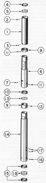
4G1. Description of the seventh, eighth, and
ninth reduced tube sections. Figure 4-18 shows the
auxiliary upper telescope system assembly. All
bubble numbers in Section 4G1, 2, and 3 refer
to Figure 4-18 unless otherwise specified.
Ill. No.
Drawing Number
Num- ber Re- quired
Nomenclature
1
P-1306-2
1
Ninth reduced tube section
2
P-1310-11
1
Auxiliary upper eyepiece lens clamp ring lockscrew
3
P-1310-19
2
Ninth and eighth reduced tube section lockscrews
4
P-1314-7
1
Auxiliary upper eyepiece lens clamp ring
5
P-1418-5
1
Auxiliary upper eyepiece lens
6
P-1306-1
1
Eighth reduced tube section
7
P-1179-75
1
Circumferential alignment lockscrew
8
P-1306-3
1
Ninth reduced tube section clamp ring
Ill. No.
Drawing Number
Num- ber Re- quired
Nomenclature
9
P-1306-4
1
Telemeter lens mount
10
P-1306-5
1
Telemeter lens clamp ring
11
P-1310-19
5
Ninth reduced tube section clamp ring and seventh and eighth reduced tube section lockscrews
12
P-1310-20
2
Telemeter lens clamp ring lockscrews
13
P-1418-6
1
Telemeter lens
14
P-1305-7
1
Seventh reduced tube section
15
P-1305-5
2
Auxiliary upper objective lens clamp rings
16
P-1310-21
4
Sixth and seventh reduced tube section lockscrews
17
P-1310-22
2
Auxiliary upper objective lens clamp ring lockscrews
18
P-1418-7
1
Auxiliary upper objective lens
69
Figure 4-18. Auxiliary upper telescope system
assembly.
a. Sections. The auxiliary upper telescope
system consists of three reduced tube sections
of a unit power telescope, making up the necessary length and carrying parts which locate
the lenses in appropriate relation to their focal
lengths. This system consists of the seventh,
eighth, and ninth reduced tube sections.
b. Ninth reduced tube section. The ninth
reduced tube section (1) is made of brass tubing and is 4 7/16 inches in length. Its upper part
is a sliding fit into the bore of the lower part
of the skeleton head (20, Figure 4-17). At
assembly, four shallow vertical recess fiats are
located on the periphery to provide clearance for
the prism tilt and change of power shifting
wire tapes (38, Figure 4-28). The inside diameter is bored for light transmission and is provided with anti-reflection threads.
The upper part is counterbored a short distance to serve as a mount for the auxiliary upper
eyepiece lens (5). It has an additional counterbored section which is threaded to receive the
auxiliary upper eyepiece lens clamp ring (4).
The clamp ring is secured with a lockscrew (2)
which screws into the tapped hole in the upper
part of this reduced tube section.
The lower part of the ninth reduced tube
section (1) is counterbored with an additional
counterbored and internal threaded section of
1.125 inches in length. The smooth counterbored
section is a sliding fit over the upper part of the
eighth reduced tube section (6) and serves as an
alignment support section. The threaded part
of the additional counterbored section screws
vertically on the threaded periphery of the
eighth reduced tube section (6) to provide the
necessary vertical focusing travel of the mounted
auxiliary upper eyepiece lens (5). The necessary
movement of this lens in atmospheric pressure
to compensate for the introduction of nitrogen
is explained under Section 4U8, Step 18, and
Section 4V7. The lower part of the ninth reduced tube section (1) is secured with two
lockscrews (3) which are inserted into tapped
holes in the upper part of the eighth reduced
tube section.
c. Auxiliary upper eyepiece lens. The auxiliary upper eyepiece lens (5) is made of two optical elements, consisting of a divergent meniscus
flint element cemented to a double convex crown
70
element, forming a positive doublet. It is mounted
in the upper part of the ninth reduced tube section (1) with the crown element resting in the
seat of the counterbored section, and is secured
with an auxiliary upper eyepiece lens clamp ring
(4) secured with a lockscrew (2).
d. Auxiliary upper eyepiece lens clamp
ring. The auxiliary upper eyepiece lens clamp ring
(4) is threaded on its periphery to screw into the
upper part of the ninth reduced tube section (1)
to retain the auxiliary upper eyepiece lens with
sufficient tension. It is kept from backing out by
a lockscrew (2) protruding into the spotted recess in the threaded, periphery from the tapped
hole in the ninth reduced tube section (1). The
clamp ring has opposite slots in the upper face to
permit it to be tightened or loosened.
e. Eighth reduced tube section. The eighth
reduced tube section (6) is made of brass tubing
and is 5.150 inches in length. Its inside diameter
is bored for light transmission and is provided
with anti-reflection threads. At assembly, the
large periphery has four shallow vertical recess
grooves to provide clearance for the prism tilt
and change of power shifting wire tapes (38, Figure 4-28). The upper part is turned to a sliding
clearance fit and serves as an alignment support
in the ninth reduced tube section (1).
The threaded periphery of the eighth reduced
tube section is threaded an ample distance to
accommodate the ninth reduced tube section
clamp ring (8) and to permit the vertical focusing
adjustment of the ninth reduced tube section.
The lower part of the eighth reduced tube section has a smooth counterbored section to carry
the telemeter lens mount (9) which is a sliding
fit. It also serves as an alignment support section
for the upper alignment support section of the
seventh reduced tube section (14). Two opposite air channels are located in this counterbored
section for the upward passage of nitrogen. A
circumferential slot with an additional circumferential recess is provided a short distance from
the lower end of this counterbored section to
accommodate an angular alignment lockscrew
(7). It is used to permit angular adjustment of
the telemeter lens mount during collimation, so
that the telemeter lens line lies in a true vertical
plane. The circumferential alignment lockscrew
extends through the circumferential slot into a
tapped hole in the telemeter lens mount (9),
while the head of the lockscrew rests on the
radial recess face. The lower part of the smooth
counterbored section of this reduced tube section
has an additional counterbored threaded section
to screw on the threaded periphery in the upper
part of the seventh reduced tube section (14). It
is secured to the seventh reduced tube section
with four lockscrew (11). These lockscrew are
inserted into countersunk clearance holes in the
lower part of this reduced tube section and
screwed into tapped holes in the upper alignment
support section of the seventh reduced tube
section.
f. Ninth reduced tube section clamp ring.
The ninth reduced tube section clamp ring (8) is
made of nominal thickness and width. The inside
diameter is threaded to screw on the threaded
periphery of the upper part of the eighth reduced
tube section, and is provided with two opposite
drilled holes to accommodate a special spanner
wrench. This clamp ring screws up tightly against
the lower face of the ninth reduced tube section
after its final adjustment and is secured with a
lockscrew (11). This lockscrew extends into a
tapped hole in the threaded periphery of the
eighth reduced tube section. After assembly the
clamp ring is provided with four shallow vertical
flat faces to allow clearance for the prism tilt
and change of power shifting tapes (38, Figure
4-28).
g. Telemeter lens. The telemeter lens (13) is
made of one flint plano convex element. The
plano surface is etched with vertical and horizontal calibrations in degrees of true field, and
provides a means of measuring the angular size of
a target. Refer to Section 4U7, Paragraph (a) for
further detail.
The telemeter lens is placed in the image plane
of the auxiliary upper telescope, and the first real
image plane of the periscope, so that the graduations appear to vibrate in unison with the image
and observation is easier.
The telemeter lens periphery is provided with
a stoned vertical recess groove for the protruding
lockscrew of the telemeter lens mount (9), thus
permitting it to be reassembled in its original
position, and preventing any angular, shift of the
telemeter lens in the mount. The plano surface
of the lens is placed toward the seat of the mount
71
and is secured with a clamp ring (10) and lockscrew (17).
h. Telemeter lens mount. The telemeter
lens mount (9) is made of brass tubing and is
0.562 inch in width. Its inside diameter is bored
for light transmission and threaded for anti-reflection. The mount is a sliding fit in the smooth
counterbored section in the lower part of the
eighth reduced tube section (6), and is secured
after collimation with the circumferential alignment lockscrew (7). The mount is counterbored
to carry the telemeter lens (13) and the telemeter
lens clamp ring (10). The mount is provided with
a small screw located as a permanent fitting and
filed off so that the protruding section of the
screw allows the free disassembly and reassembly
of the telemeter lens in the mount. This protruding section of the screw, when engaged in the
stoned vertical recess groove of the telemeter lens
periphery, prevents it from shifting angularly in
the mount and also provides the original reassembly of the lens in the mount. Two opposite drilled
holes are provided in the lower part of the mount
to receive a special tool which is used to remove
the mount from the eighth reduced tube section.
i. Telemeter lens clamping. The telemeter lens clamp ring (10) is made of brass tubing
and is of nominal thickness and width. It is a
push fit in the counterbored section of the telemeter lens mount (9). This clamp ring fits snugly
against the convex surface of the telemeter lens,
and is secured with two opposite lockscrews (12).
These lockscrews extend into tapped holes in the
upper part of the telemeter lens mount and into
the partially tapped hole of each clamp ring.
j. Seventh reduced tube section. The
seventh reduced tube section (14) is made of
brass tubing and is 8.161 inches in length. At
assembly it is provided with four shallow vertical
recess grooves the entire length to allow sufficient
clearance for the prism tilt and change of power
shifting wire tapes (38, Figure 4-28). The upper
part is machine-turned to serve as an alignment
support section, and is a sliding fit in the small
counterbored section in the lower part of the
eighth reduced tube section (6). The threaded
periphery section in the upper part receives the
counterbored threaded section in the lower part of
the eighth reduced tube section (6) and is secured
with four lockscrews (11). These lockscrews are
inserted into countersunk clearance holes in the
lower part of the eighth reduced tube section, and
screwed into tapped holes in the upper alignment support section of the seventh reduced tube
section. Two opposite air holes of 0.060-inch
diameter are located 0.060 inch from the upper
end of the alignment support section in the upper
part of this reduced tube section.
The inside diameter is bored for light transmission and threaded for anti-reflection. The
lower part of the seventh reduced tube section
has a counterbored threaded section of 1 1/16
inches. This counterbored threaded section
serves as a mount for the auxiliary upper objective lens (18), and is secured with two auxiliary
upper objective lens clamp rings (15). One clamp
ring serves as a seat for the flint element of the
lens doublet in the upper part of this section,
while the second clamp ring secures snugly
against the crown element of the lens doublet
in the lower part of this section. Each clamp ring
is secured with a lockscrew (17). Two opposite
shallow vertical grooves in the threaded wall of
this section provide for nitrogen passage.
An additional counterbore of 1.157 inches in
length is provided to serve as an alignment support section with the lower part of 0.340-inch
length of this section threaded. This threaded
section screws on the threaded periphery of the
sixth reduced tube section (1, Figure 4-19) of
the auxiliary lower telescope system and is secured with four lockscrews (16). These lockscrews extend into countersunk clearance holes
and into tapped holes in the alignment support
section of the sixth reduced tube section.
k. Auxiliary upper objective lens. The auxiliary upper objective lens (18) is made of two
optical elements, consisting of a divergent meniscus flint element cemented to a double convex
crown element, forming a positive doublet. It is
mounted in the threaded counterbore section in
the lower part of the seventh reduced tube section (14) with two auxiliary upper objective lens
clamp rings (15) located on opposite sides of the
lens.
l. Auxiliary upper objective lens clamp
rings. The auxiliary upper objective lens clamp
rings (15) are made of brass tubing and are of
nominal thickness and width. Both clamp rings
are identical, with the periphery threaded, and
72
each has opposite slots in one of the side faces to
accommodate a special wrench.
One clamp ring is inserted into the threaded
counterbore in the lower part of the seventh
reduced tube section before insertion of the
auxiliary upper objective lens (18). The second
clamp ring contacts the lower side of the objective lens. Each clamp ring is secured with a
lockscrew (17), which extends into the countersunk clearance hole in the dower part of the
seventh reduced tube section (14) and into the
tapped hole in each clamp ring.
4G2. Disassembly of the seventh, eighth, and ninth
reduced tube sections. The seventh, eighth, and
ninth reduced tube sections are disassembled
in the following manner:
1. Remove the two lockscrews (11) from the
lower part of the eighth reduced tube section
6). These lockscrews are unscrewed from tapped holes in the upper part of the external
alignment support section of the seventh reduced tube section (14).
2. Unscrew the seventh reduced tube section
14) from the eighth reduced tube section (6).
3. Remove the two lockscrews (17) from
the lower part of the seventh reduced tube
section. These lockscrews are unscrewed from
tapped holes in the two auxiliary upper objective lens clamp rings (15).
4. Remove the lower clamp ring (15), unscrewing it with a special wrench from the
lower part of the seventh reduced tube section.
5. The auxiliary upper objective lens (18)
slides out easily. This is done by turning this
reduced tube section on its lower end over clean
lens tissue, and tapping, around the periphery
with a light rawhide mallet. Make certain that
the lens drops lightly on soft lens tissue.
6. Unscrew the upper clamp ring (15) in the
same manner as noted under Step 4.
7. Remove the two lockscrews (3) from the
lower part of the ninth reduced tube section (1).
8. Unscrew the ninth reduced tube section
(1) from the eighth reduced tube section (6).
9. Remove the lockscrew (11) from the ninth
reduced tube section clamp ring (8). This
lockscrew is unscrewed from the tapped hole in the
threaded periphery of the eighth reduced tube
section. Unscrew the clamp ring (8) from the
eighth reduced tube section.
10. Remove the circumferential alignment
lockscrew (7). This lockscrew is unscrewed from
the tapped hole in the telemeter lens mount (9),
and is removed from the circumferential slot in
the eighth reduced tube section.
11. Remove the telemeter lens mount (9)
from the lower part of the eighth reduced tube
section. This is done by means of a special pair
of calipers. The two rounded ends of the calipers
fit into opposite drilled holes in the lower part
of the mount.
12. Remove the two lockscrews (12) from
opposite sides of the telemeter lens mount (9).
These lockscrews are unscrewed from tapped
holes in the telemeter lens clamp ring (10).
13. Turn the telemeter lens mount (9) with
its upper face on a piece of lens tissue. If necessary, using a piece of lens tissue, press downward
on the upper side of the telemeter lens (13),
removing both the lens and the clamp ring (10).
Wrap the lens in clean lens tissue and store in a
box to prevent scratches and breakage.
14. Remove the lockscrew (2) from the upper
part of the ninth reduced tube section (1). This
lockscrew is unscrewed from the tapped hole in
the auxiliary upper eyepiece lens clamp ring (4).
15. Unscrew the auxiliary upper eyepiece lens
clamp ring (4), using a special wrench.
16. Place the upper end of the ninth reduced
tube section on a piece of lens tissue. If necessary, tap lightly on the periphery of this reduced
tube section with a small rawhide mallet. The
auxiliary upper eyepiece lens (5) should slide
out easily.
17. Wrap all lenses in clean lens tissue and
place to one side, to prevent scratches and
breakage.
4G3. Reassembly of the seventh, eighth, and ninth
reduced tube sections. The seventh, eighth, and
ninth reduced tube sections are reassembled in
the following manner:
1. Using an air line pressure hose, blow out
the internal surfaces of the seventh reduced
73
tube section. If a circular brush is available, it
should be used first. This procedure should be
carried out with each succeeding reduced tube
section, and with the clamp rings and lens
mounts.
2. Place the upper clamp ring (15) in the
threaded counterbored section in the lower
part of the seventh reduced tube section and
screw it in until the lockscrew holes coincide.
3. Insert and secure the lockscrew (17) in
the countersunk clearance hole in the lower part
of the seventh reduced tube section and screw
it into a tapped hole in the upper clamp ring (15).
4. Clean the auxiliary upper objective lens
(18) with clean lens tissue. Surface dust can be
removed with a rubber air bulb and a camel's
hair brush. A vacuum brush used with ether is
also effective.
5. Place the objective lens of this system
in the lower part of the seventh reduced tube
section, turning the flint side of the lens doublet
toward the lower face of the upper clamp ring
(15).
6. Place the lower clamp ring (15) in the
same threaded counterbored section on the
lower face or crown side of the objective lens.
Screw this clamp ring tightly against the objective lens with a special wrench. The lockscrew
holes should coincide when this lens is tightened
sufficiently.
7. Insert and secure the lockscrew (17) in
the countersunk clearance hole in the lower part
of the seventh reduced tube section and screw
it into a tapped hole in the lower clamp ring
(15).
8. Place the ninth reduced tube section clamp
ring (8) on the threaded periphery of the eighth
reduced tube section (6), screwing it beyond its
locking position.
9. Clean the telemeter lens (13) in similar
manner to that outlined under Step 4.
10. Place the telemeter lens (13) in the telemeter lens mount (9) with the etched graduations
resting against the shoulder of the mount, and
the stoned vertical recess groove meshing with
the inward protruding screw in the mount.
11. Slide the telemeter lens clamp ring (10)
into the telemeter lens mount so that it coincides
with the lockscrew holes in the mount.
12. Insert and secure the two lockscrews (12)
in the tapped holes in the mount and clamp
ring (10).
13. Slide the telemeter lens (13) with its
mount (9) into the lower part of the eighth reduced tube section with the etched graduated
surface facing the lower part of this reduced
tube section and the curvature facing upward.
14. Insert the circumferential alignment lockscrew (7) through the circumferential slot in
the lower part of the eighth reduced tube section. This lockscrew extends into the tapped
hole in the telemeter lens mount (9).
15. Screw the lower part of the eighth reduced tube section (6) on the upper part of
the seventh reduced tube section (14) until the
lockscrew holes coincide. The upper face of the
seventh reduced tube section almost contacts
the lower face of the telemeter lens mount, and
prevents axial movement of the mount.
16. Secure the seventh and eighth reduced
tube sections with four lockscrews (11). These
lockscrews are inserted in countersunk clearance holes in the eighth reduced tube section
and screwed into tapped holes in the upper part
of the alignment support section of the seventh
reduced tube section.
17. Clean the auxiliary upper eyepiece lens
(5) in similar manner to that outlined in Step 4.
18. Place the auxiliary upper eyepiece lens
in the seat of the upper part of the ninth reduced tube section with the crown side of the
lens doublet against the seat of this section.
19. Screw the auxiliary upper eyepiece lens
clamp ring (4) into and against the lens tightly
to insure that the tapped holes coincide.
20. Place the lockscrew (2) in the tapped
holes in both the ninth reduced tube section (1)
and the clamp ring (4) for securement.
21. Place an auxiliary telescope at the lower
part of the seventh reduced tube section. Set
the auxiliary telescope diopter at infinity for
the observer. (This setting should be based on
74
at least five observations of an infinity target
which give consistent readings.) Check the
definition on the telemeter lens through the
auxiliary upper objective lens. It should correspond to the diopter setting on the auxiliary
telescope. Should the focusing of this lens
doublet indicate that the previous factory
setting is correct, the-auxiliary upper eyepiece
lens is assembled.
22. Screw the lower part of the ninth reduced
tube section (1) onto the upper part of the eighth
reduced tube section (6).
23. With the use of an infinity target, primary collimation of this auxiliary upper telescope system is carried out in the following
manner. The ninth reduced tube section is
moved downward, focusing the auxiliary upper
eyepiece lens until the image of the target is
apparent on the telemeter lens. At this setting,
the auxiliary telescope is focused from plus
diopter to the observer's diopter reading. Check
at this diopter reading to ascertain that the
telemeter graduations are in sharp definition
and that there is no parallax apparent on the
telemeter lens.
24. This auxiliary upper telescope system,
being of unit power magnification, requires
the use of an auxiliary telescope to set the system to zero diopter. This constitutes the primary collimation of this telescope system. Any
error in this telescope system when assembled
to the rest of the instrument is apparent when
magnified at 6 power.
25. Keep the lockscrews (3) which secure the
ninth reduced tube section (1) to the eighth reduced tube section (6) and the ninth reduced
tube section clamp ring lockscrew (11) in a small
box until the final collimation on a distance target of 1200 feet at atmospheric pressure is
completed.
H. AUXILIARY LOWER TELESCOPE SYSTEM
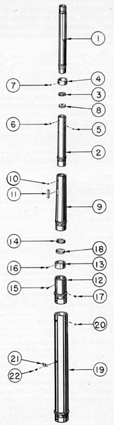
4H1. Description of the second, third, fourth,
fifth, and sixth reduced tube sections. Figure 4-19
shows the auxiliary lower telescope system assembly. All bubble numbers in Sections 4H1, 2,
and 3 refer to Figure 4-19 unless otherwise
specified.
Ill. No.
Drawing Number
Num- ber Re- quired
Nomenclature
1
P-1305-6
1
Sixth reduced tube section
2
P-1305-2
1
Fifth reduced tube section
3
P-1305-5
1
Auxiliary lower objective lens clamp ring
4
P-1305-8
1
Taper guide
5
P-1310-22
1
Auxiliary lower objective lens clamp ring lockscrew
6
P-1310-23
4
Fifth and sixth reduced tube section lockscrews
7
P-1310-24
4
Taper guide lockscrews
8
P-1418-7
1
Auxiliary lower objective lens
9
P-1305-1
1
Fourth reduced tube section
10
P-1310-24
4
Fourth and fifth reduced tube section lockscrews
11
P-1361-7
1
Air line adapter
12
P-1304-9
1
Third reduced tube section
Ill. No.
Drawing Number
Num- ber Re- quired
Nomenclature
13
P-1305-3
1
Auxiliary lower eyepiece lens mount
14
P-1305-4
1
Auxiliary lower eyepiece lens clamp ring
15
P-1310-25
4
Third and fourth reduced tube section lockscrews
16
P-1310-26
1
Auxiliary lower eyepiece lens clamp ring lockscrew
17
P-1310-27
2
Auxiliary lower eyepiece lens mount lockscrews
18
P-1418-8
1
Auxiliary lower eyepiece lens
19
P-1304-8
1
Second reduced tube section
20
P-1310-28
4
Second and third reduced tube section lockscrews
21
P-1362-13
1
Air line strap
22
P-1422-1
2
Air line strap lockscrews
a. Sections. The auxiliary lower telescope
system consists of five reduced tube sections of a
unit power telescope which make up the necessary length and carry six parts which locate the
lenses in appropriate relation to their focal
lengths. The system consists of the second, third,
fourth, fifth, and sixth reduced tube sections,
b. Sixth reduced tube section. The sixth
reduced tube section (1) is made of brass tubing
75
Figure 4-19. Auxiliary lower telescope system assembly.
and is 10.309 inches in length. It serves to provide
only the necessary distance between the auxiliary upper and lower telescope systems. At assembly, four vertical shallow recess grooves are
provided 3 1/2 inches from the upper part, to allow
clearance for the prism tilt and change of power
shifting wire tapes (38, Figure 4-28). Its inside
diameter is bored for light transmission and is
provided with anti-reflection threads.
The upper part is turned a sliding fit and
serves as an alignment support section in the
counterbored alignment support section in the
lower part of the seventh reduced tube section.
The threaded periphery section in the upper part
of this reduced tube section receives the counterbored threaded section in the lower part of the
seventh reduced tube section (14, Figure 4-18)
and is secured with four lockscrews (16) of the
auxiliary upper telescope system assembly.
The lower part is turned a sliding fit and serves
as an alignment support section in the counterbored alignment support section in the upper
part of the fifth reduced tube section (2). The
threaded periphery section in the lower part
screws into the threaded counterbore in the upper
part of the fifth reduced tube section, and is secured with four lockscrews (6) which are inserted into countersunk clearance holes in the
upper part of the fifth reduced tube section (2)
and screwed into tapped holes in the lower alignment support section of the sixth reduced tube
section (1). The lower part has a shoulder 1/4 inch
wide and its diameter coincides with the diameter
of the upper part of the fifth reduced tube
section.
c. Fifth reduced tube section. The fifth reduced tube section (2) is made of brass tubing,
and is 7.187 inches in length. The upper part of
its external wall is straight turned a distance of
4 inches. A taper guide is located on this surface
with a center distance of approximately 2 1/4
inches from the upper face and is secured to this
reduced tube section with four lockscrews (7).
From the 4-inch turned section, the lower part of
this reduced tube section is tapered outward for
1 15/16 inches at which point there is a shoulder
1/8 inch wide. The diameter of this shoulder coincides with the diameter of the upper part of the
fourth reduced tube section (9). The part below
the large shoulder is straight turned a short
76
distance to serve as an alignment support section
with a threaded periphery section above it. The
alignment support section is a sliding fit into the
counterbored alignment support section, while
the threaded periphery screws into the threaded
counterbored section in the upper part of the
fourth reduced tube section. It is secured with
four lockscrews (10) which are inserted in countersunk clearance holes in the lower part of the
fourth reduced tube section and screwed into
tapped holes in the upper alignment support section of the fifth reduced tube section.
This reduced tube section is bored to a diameter of 0.946 inch for light transmission. The
lower part is counterbored with a taper, which
tapers inward from the lower end and upward for
a distance of 3 15/16 inches. From this point it
remains a straight counterbored section for a distance of 2 3/16 inches. The tapered and straight
counterbored sections are provided with anti-reflection threads. This reduced tube section tapers
principally to allow sufficient space, and to form
a wall around the marginal or oblique light ray
bundles. These bundles diverge downward from
the auxiliary lower objective lens (8), through
the fourth reduced tube section (9) to the auxiliary lower eyepiece lens (18) of the third reduced
tube section (12).
The upper part of the fifth reduced tube section is counterbored an appropriate distance to
serve as a mount for the auxiliary lower objective
lens (8) with an internal threaded section to accommodate the auxiliary lower objective lens
clamp ring (3). Two opposite shallow air channels
located in the inner wall of this mount section
and protruding into the seat of the mount permit passage of the charging nitrogen. An additional counterbored section serves as an alignment support section with an internal threaded
section above it to receive the upper alignment
support section and the threaded periphery of
the 6th reduced tube section (1).
d. Taper guide. The taper guide (4) is made
of brass tubing, with a nominal wall thickness,
and is 5/8 inch in width. The upper part is tapered
slightly at assembly to allow about 0.005 inch
clearance on the diameter with the inside wall of
the outer taper section (1, Figure 4-15). The bore
of the taper guide is a push fit on the upper part
of the fifth reduced tube section (2). The inside
walls have four vertical shallow recess grooves,
two opposite each other to provide clearance for
the prism tilt and change of power shifting wire
tapes (38, Figure 4-28). It is secured with four
lockscrews (7) which extend into countersunk
clearance holes in the taper guide and screw into
tapped holes in the fifth reduced tube section.
The taper guide provides a support for the reduced tube sections in the outer taper section (1,
Figure 4-15).
e. Auxiliary lower objective lens. The auxiliary lower objective lens (8) is identical to the
auxiliary upper objective lens (18, Figure 4-18)
of the auxiliary upper telescope system. The flint
element of this doublet is secured against the
shoulder seat in the fifth reduced tube section by
means of a threaded auxiliary lower objective
lens clamp ring (3) which is secured with a lockscrew (5).
f. Auxiliary lower objective lens clamp
ring. The auxiliary lower objective lens clamp
ring (3) is identical to the auxiliary upper objective lens clamp rings (15, Figure 4-18) of the
auxiliary upper telescope system. The clamp ring
is inserted in the threaded counterbore in the
lower part of the fifth reduced tube section, and
contacts the crown element side of the auxiliary
lower objective lens to secure the lens doublet
snugly. The clamp ring is secured from unscrewing by the insertion of a lockscrew (5) which is
inserted into a countersunk clearance hole in the
lower part of the fifth reduced tube section and
screwed into a tapped hole in the clamp ring.
g. Fourth reduced tube section. The
fourth reduced tube section (9) is made of brass
tubing, and is 7.937 inches in length. Its external
diameter is tapered, with the inside diameter
tapered in the same proportion allowing the wall
a nominal thickness. It is provided with antireflection threads.
The lower part of the fourth reduced tube section has a shoulder 3/16 inch in width, located at
the lower part of the taper. Its diameter coincides
with the diameter in the upper part of the third
reduced tube section (12). Below this shoulder,
the lower part is turned straight, and is provided
with an alignment support section and threaded
periphery. The alignment support section is a
sliding fit in the upper counterbored alignment
section in the third reduced tube section, while
77
the threaded periphery screws into the threaded
counterbored section of the same reduced tube
section. It is secured with four lockscrews (15)
which are inserted in countersunk clearance
holes in the upper part of the third reduced tube
section and screwed into tapped holes in the
lower alignment support section of the fourth reduced tube section.
The upper part is counterbored straight a
depth of 1.130 inches, to serve as an alignment
support section with a portion threaded to receive the alignment support section and threaded
periphery in the lower part of the fifth reduced
tube section. In the upper part a 1/8-inch diameter hole is drilled through the wall and is located
1.571 inches from the upper end, for the assembly
of an air line adapter (11).
h. Air line adapter. The air line adapter (11)
consists of a piece of flat brass air line, with the
upper end closed, provided with a 1/8-inch diameter drilled hole located 7/64 inch from the upper
end. The adapter is soldered to the periphery in
the upper part of the fourth reduced tube section
(9) with 1/8-inch holes in coincidence. The lower
opening of the adapter receives the air line section (18) shown on the upper telescope system
Part I assembly (Figure 4-20).
i. Third reduced tube section. The third
reduced tube section (12) is made of brass tubing
and is 3.562 inches in length. It is bored straight
for light transmission, and carries the auxiliary
lower eyepiece lens mount (13) which is a sliding
axial fit in its central part.
Its external diameter is a step larger than
the preceding reduced tube section, and it has a
large shoulder 1/8 inch in width. This shoulder
forms a flange, with a diameter that coincides
with the diameter of the upper part of the
second reduced tube section (19). The part
below the shoulder flange is turned straight,
with a threaded periphery and an alignment
support section. The alignment support section
is a sliding fit into the counterbored alignment
support section in the upper part of the second
reduced tube section, while its threaded periphery screws into the internal threaded section in
the same counterbored section. It is secured
with four lockscrews (20) which are inserted
into countersunk clearance holes in the upper
part of the second reduced tube section and
screwed into tapped holes in the lower alignment support section of the third reduced tube
section.
The center part of this reduced tube section
has opposite axial slots of appropriate length in
which the auxiliary lower eyepiece lens (18)
and its mount (13) are focused in the primary
and final collimation of the auxiliary upper and
lower telescope system.
The bore of the upper part is provided with
a partially threaded section to receive the
threaded periphery of the lower part of the
fourth reduced tube section, while the bore
serves as an alignment support section for the
lower alignment support section of the fourth
reduced tube section.
The lower part is counterbored a depth of
1.125 inches upward to provide clearance for
light transmission and to lighten the reduced
tube section. The air line section (18) shown
on the upper telescope system Part I (Figure
4-20) extends downward from the fourth reduced tube section over this reduced tube
section.
j. Auxiliary lower eyepiece lens. The auxiliary lower eyepiece lens (18) is made of two
optical elements, consisting of a double convex
crown element cemented to a divergent meniscus
flint element, forming a positive doublet. It is
mounted in the auxiliary lower eyepiece lens
mount (13) with the flint element resting in
the seat of the counterbored section of the
mount, and is secured with an auxiliary lower
eyepiece lens clamp ring (14) which is secured
with a lockscrew (16).
k. Auxiliary lower eyepiece lens mount.
The auxiliary lower eyepiece lens mount (13)
is made of brass tubing, and is 0.780 inch in
length. It is bored for light transmission, and is
provided with two counterbored sections. The
small counterbored section carries the auxiliary
lower eyepiece lens (18), while the large counterbored section is threaded to receive the auxiliary
lower eyepiece lens clamp ring (14) which is
secured with a lockscrew (16). The mount is a
sliding fit in the bore of the third reduced tube
section, and is moved axially to focus the auxiliary lower eyepiece lens (18) for fine
78
adjustments for the removal of parallax at primary
and final collimation.
Two opposite narrow air channels in the
periphery permit passage of charging nitrogen.
A tapped hole is provided to receive a screw
which is inserted temporarily through the axial
slot of the third reduced tube section during
collimation, to focus the mount axially, thus
carrying the auxiliary lower eyepiece lens (18)
vertically for adjustments required.
The face of the mount is beveled inward at
45 degrees to prevent restriction to the light rays that
are deflected downward. The mount is secured
with two lockscrews (17) which are inserted
into countersunk clearance holes in the third
reduced tube section and screwed into tapped
holes in the mount. Two opposite drilled holes
are provided in the upper wall of the mount
to receive a special tool which is used to remove
the mount from the third reduced tube section.
l. Auxiliary lower eyepiece lens clamp
ring. The auxiliary lower eyepiece lens clamp
ring (14) is made of brass tubing and is of
nominal thickness and width. The periphery
is threaded to screw into the threaded counterbore of the auxiliary lower eyepiece lens mount
(13) to secure the lens. The upper face of the
clamp ring is beveled at 30 degrees with a matching
inside bevel from an undercut groove of the
bore, thus providing a 1/64-inch upper wall to
secure the lens sufficiently and a shock support
to the crown element of the lens. The remaining bore is tapered outward. Two opposite
slots are provided in the side face of the clamp
ring for the insertion of a special wrench. The
clamp ring is secured with a lockscrew (16)
which is inserted in a countersunk hole in the
mount and screwed into a tapped hole in the
clamp ring.
m. Second reduced tube section. The
second reduced tube section (19) is made of
brass tubing, and is 16.300 inches in length.
It serves to enclose the light rays to the designed clear aperture area, and to provide the
necessary distance between the auxiliary lower
telescope system and the upper telescope system assembly Part I. Its outside diameter is
uniform for its entire length, with the exception
of the lower part. This part has a shoulder flange
3/16 inch in width, the outside diameter coinciding
with the diameter of the upper part of
the first reduced tube section shown in Figure
4-20 of the upper telescope system assembly
Part I.
The lower part below the shoulder flange is
turned to serve as an alignment support section and is a sliding fit in the counterbored
alignment support section in the first reduced
tube section (1, Figure 4-20). The threaded
periphery screws into the threaded section of
the same counterbore. It is secured with four
lockscrews (8) which are inserted in countersunk clearance holes in the upper part of the
first reduced tube section (1, Figure 4-20) and
screwed into tapped holes in the lower alignment
support section of the second reduced tube section (19).
The inside diameter is bored for light transmission and is provided with anti-reflection
threads up to the upper alignment support
section. The bore in the upper part serves as
an alignment support section and is threaded
above the upper part, to receive the lower
alignment support section and the threaded
periphery of the third reduced tube section (12).
The air line section (18, Figure 4-20) of the
upper telescope system assembly Part I, extends downward the entire length of this reduced tube section. It is secured to it with a
removable air line strap (21) which is secured
with two lockscrews (22). These lockscrews
are inserted in clearance holes in the air line
strap (21) and screwed into tapped holes in
the wall of this reduced tube section.
4H2. Disassembly of the second, third, fourth,
fifth, and sixth reduced tube sections. The second,
third, fourth, fifth, and sixth reduced tube
sections are disassembled in the following
manner:
1. Remove the four lockscrews (6) from the
upper part of the fifth reduced tube section (2).
These lockscrews are unscrewed from tapped
holes in the lower alignment support section of
the sixth reduced tube section (1).
2. Unscrew the sixth reduced tube section
(1) from the fifth reduced tube section (2).
3. Remove the lockscrew (5) from the upper
part of the fifth reduced tube section (2). This
79
lockscrew is unscrewed from the tapped hole in
the auxiliary lower objective lens clamp ring (3).
4. Using a special wrench, unscrew the
clamp ring (3).
5. Place the upper end of the fifth reduced
tube section (2) on a piece of clean lens tissue,
allowing the auxiliary lower objective lens (8)
to slide out.
6. Remove the four lockscrews (7) from the
taper guide (4). These lockscrews are unscrewed
from tapped holes in the wall of the fifth reduced
tube section (2).
7. Carry the taper guide (4) off the upper
part of the fifth reduced tube section (2).
8. Remove the four lockscrews (10) from
the upper part of the fourth reduced tube section. These lockscrews are unscrewed from the
tapped holes in the lower alignment support
section of the fifth reduced tube section (2).
9. Unscrew the fifth reduced tube section
(2) from the upper part of the fourth reduced
tube section (9).
10. Remove the four lockscrews (15) from
the upper part of the third reduced tube section (12). These lockscrews are unscrewed from
the tapped holes in the lower alignment support
section of the fourth reduced tube section (9).
11. Unscrew the fourth reduced tube section
(9) from the upper part of the third reduced
tube section (12).
12. Remove the two lockscrews (17) from the
central part of the third reduced tube section
(12). These lockscrews are unscrewed from
tapped holes in the auxiliary lower eyepiece lens
mount (13).
13. Turn the assembled third and second reduced tube sections so that the third reduced
tube section is facing downward. Tap lightly on
the periphery of the third reduced tube section
(12) with a light rawhide mallet. The assembled
auxiliary lower eyepiece lens (18) and its mount
(13) with the clamp ring (14) should slide out
easily.
14. Remove the lockscrew (16) from the
periphery of the auxiliary lower eyepiece lens
mount (13), unscrewing it from the tapped hole
in the clamp ring (14).
15. Using a special wrench, unscrew the clamp
ring (14) from the auxiliary lower eyepiece lens
mount (13).
16. Place the upper end of the mount (13)
on a piece of clean lens tissue. The auxiliary
lower eyepiece lens (18) should drop out easily.
If difficulty should be encountered, place a piece
of clean lens tissue over the mount and push
downward.
17. Remove the four lockscrews (20) from the
upper part of the second reduced tube section
(19). These lockscrews are unscrewed from
tapped holes in the lower alignment support
section of the third reduced tube section (12).
18. Unscrew the third reduced tube section
(12) from the upper part of the second reduced
tube section (19).
19. Place the lens doublets of this telescope
system to one side, to prevent scratches or
breakage.
4H3. Reassembly of the second, third, fourth,
fifth, and sixth reduced tube sections. The second
third, fourth, fifth, and sixth reduced tube sections are reassembled in the following manner:
1. Using an air hose, blow out the internal
surface of the sixth reduced tube section. If a
circular brush is available, it should be used before the air hose. This procedure is carried out
with each reduced tube section of this assembly,
and also with the clamp rings and lens mounts.
2. Clean the auxiliary lower objective lens
(8) with clean lens tissue. Surface dust can be
removed with a rubber air bulb and a camel's
hair brush; a vacuum brush used with ether is
also effective.
3. Place the objective lens of this system in
the upper part of the fifth reduced tube section
(2). The lens doublet should be placed so that the
flint element is resting against the seat of the
mount section.
4. Place the clamp ring (3) in the threaded
counterbored section of the upper part of the
fifth reduced tube section (2). Screw the clamp
ring tight against the crown element of the lens
doublet. The lockscrew holes should coincide
when this lens is tightened sufficiently.
80
5. Insert and secure the lockscrew (5) in the
countersunk clearance hole in the upper part of
the fifth reduced tube section (2) and screw it
into the tapped hole in the clamp ring.
6. Assemble the taper guide (4) over the
upper part of the fifth reduced tube section (2).
Push this taper guide on, noting the reference
numerals to determine its correct assembly with
the lockscrew holes. The tapered part faces
upward.
7. Insert and secure the four lockscrews (7).
These lockscrews are inserted in countersunk
clearance holes in the taper guide (4) and screwed
into tapped holes in the periphery of the fifth
reduced tube section (2).
8. Insert the threaded periphery of the lower
part of the sixth reduced tube section (1) in the
threaded counterbored section in the upper part
of the fifth reduced tube section (2). Screw it
tight until the lockscrew holes coincide.
9. Secure the sixth and fifth reduced tube
sections with the four lockscrews (6). These lockscrews are inserted in countersunk clearance
holes in the fifth reduced tube section and screwed
into tapped holes in the lower alignment support
section of the sixth reduced tube section.
10. Insert the threaded periphery of the lower
part of the fifth reduced tube section (2) in the
threaded counterbored section in the upper part
of the fourth reduced tube section (9). Screw it
tight until the lockscrew holes coincide.
11. Secure the fifth and fourth reduced tube
sections with four lockscrews (10). These lockscrews are inserted in countersunk clearance holes
in the upper part of the fourth reduced tube section (9) and screwed into tapped holes in the
lower alignment support section of the fifth reduced tube section (2).
12. Clean the auxiliary lower eyepiece lens
(18) in similar manner to that described in Step 2.
13. Place the auxiliary eyepiece lens (18) in
the mount (13) so that the flint element of this
lens doublet rests in the seat of the mount.
14. Place the clamp ring (14) in the threaded
counterbored section in the mount. Using a special wrench, screw the clamp ring tight against
the crown element of this lens doublet. The lockscrew
holes should coincide when the lens is
tightened sufficiently.
15. Insert and secure the lockscrew (16) in the
countersunk clearance hole in the mount (13) and
screw it into the tapped hole in the clamp ring
(14).
16. Slide the mounted auxiliary lower eyepiece lens (18) with the mount (13) into place in
the central part of the third reduced tube section
(12). Place the mount so that the clamp ring side
remains toward the upper part. Insert the one
lockscrew (17) temporarily to hold the mount in
place.
17. The auxiliary lower eyepiece lens mount
(13) is not secured with the two lockscrews (17)
during the primary collimation of the auxiliary
lower telescope system. The lockscrews should
be placed in a small box until the final collimation is completed.
18. Place the upper part of the third reduced
tube section (12) on the lower alignment support
section of the fourth reduced tube section (9),
screwing it on the threaded periphery.
19. Secure the fourth and third reduced tube
sections (9 and 12) with four lockscrews (15).
These lockscrews are inserted into countersunk
clearance holes in the upper part of the third
reduced tube section (12) and screwed into
tapped holes in the lower alignment support
section of the fourth reduced tube section.
20. Insert the threaded periphery of the
lower part of the third reduced tube section (12)
into the threaded counterbore of the upper part
of the second reduced tube section (19).
21. Secure the third and second reduced tube
sections (12 and 19) with four lockscrews (20).
These lockscrews are inserted into countersunk
clearance holes in the upper part of the second
reduced tube section (19) and screwed into
tapped holes in the lower alignment support
section of the third reduced tube section.
22. Assemble the auxiliary lower telescope
system assembly to the auxiliary upper telescope
system assembly. Insert the threaded periphery
of the upper part of the sixth reduced tube section (1) into the threaded counterbore of the
lower part of the seventh reduced tube section
(14, Figure 4-18).
81
23. Secure the seventh and sixth reduced tube
sections with four lockscrews (16). These lockscrews are inserted into countersunk clearance
holes in the lower part of the seventh reduced
tube section (14) and screwed into tapped holes
in the upper alignment support section of the
sixth reduced tube section (1).
24. Place an auxiliary telescope at the lower
end of the second reduced tube section. Set the
auxiliary telescope diopter at infinity for the
observer. (This setting should be based on at
least five observations of an infinity target
which give consistent readings.)
25. Move the auxiliary lower eyepiece lens in
until the image of the infinity target is apparent
on the telemeter lens. The movement of the
auxiliary lower eyepiece lens requires fine movement, as the image is lost with very little movement.
When the target is sharply apparent on
the telemeter lens there should be no parallax
observed.
26. Focus the auxiliary telescope from plus to
observe the diopter reading, taking a series of
observations to determine the correct setting of
the auxiliary lower eyepiece lens. This telescope
system, being of unit power magnification, requires the use of an auxiliary telescope to set
the system to zero diopter. This constitutes
primary collimation of the auxiliary lower telescope system to the auxiliary upper telescope
system.
27. Any error in the auxiliary lower telescope
system, when assembled to the rest of the instrument, is apparent when magnified at 6 power.
This error can be compensated during final
collimation.
I. UPPER TELESCOPE SYSTEM
4I1. Part I of the upper telescope system. The
upper telescope system is divided into two individual assemblies, namely: Part I: first reduced
tube section, fifth, and sixth inner tube sections.
Part II: second, third, and fourth inner tube
sections.
The upper telescope system is divided principally to permit familiarization as to nomenclature, description, disassembly, and reassembly.
It is composed of three lenses, namely: a
positive upper eyepiece lens doublet, a plano
convex collective, lens, and an air space upper
objective lens doublet. This system is used in
reverse to decrease the lower telescope system
to a 6 power magnification.
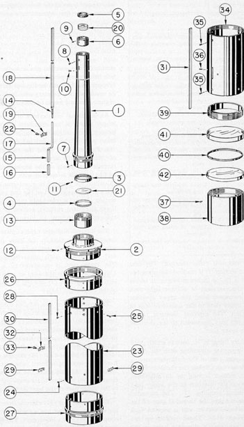
Part I: a. First reduced tube section and
fifth and sixth inner tube sections. Figure
4-20 shows the upper telescope system assembly
Part I. All bubble numbers in Section 4I1, 3
and 4 refer to Figure 4-20 unless otherwise
specified.
Ill. No.
Drawing Number
Num- ber Re- quired
Nomenclature
1
P-1304-5
1
First reduced tube section
2
P-1304-1
1
Reducing coupling
3
P-1304-2
1
Collective lens mount
Ill. No.
Drawing Number
Num- ber Re- quired
Nomenclature
4
P-1304-3
1
Collective lens clamp ring
5
P-1304-6
1
Upper eyepiece lens clamp ring
6
P-1304-7
1
Upper eyepiece lens mount
7
P-1310-7
2
Collective lens mount and diaphragm lockscrews
8
P-1310-29
4
First and second reduced tube section lockscrews
9
P-1310-30
1
Upper eyepiece lens clamp ring lockscrew
10
P-1310-31
2
Upper eyepiece lens mount lockscrews
11
P-1310-32
1
Collective lens clamp ring lockscrew
12
P-1310-33
4
Reducing coupling and first reduced tube section lockscrews
13
P-1314-14
1
Diaphragm
14
P-1362-3
1
Air line coupling
15
P-1362-6
1
Flat air line coupling
16
P-1362-7
1
Air line section (short)
17
P-1362-8
1
Air line section (bent)
18
P-1362-9
1
Air line section
19
P-1362-12
1
Air line strap
20
P-1418-9
1
Upper eyepiece lens
21
P-1418-10
1
Collective lens
22
P-1422-1
2
Air line strap lockscrews
23
P-1204-3
1
Sixth inner tube section
24
P-1179-24
8
Sixth inner tube section lower end lockscrews (soldered)
82
Ill. No.
Drawing Number
Num- ber Re- quired
Nomenclature
25
P-1179-30
4
Sixth inner tube section and reducing coupling lockscrews
26
P-1204-2
1
Sixth inner tube section upper end coupling
27
P-1204-4
1
Sixth inner tube section lower end coupling
28
P-1310-34
8
Sixth inner tube section upper end coupling lockscrews (soldered)
29
P-1361-3
2
Tape straps
30
P-1362-7
1
Air line section (soldered)
31
P-1362-7
1
Air line section (short)
32
P-1362-13
1
Air line strap
33
P-1422-1
2
Air line strap lockscrews
34
P-1204-5
1
Fifth inner tube section
35
P-1179-23
8
Fifth inner tube section lockscrews, upper and lower ends
36
P-1179-23
6
Upper objective lens mount lockscrews
37
P-1179-35
1
Upper objective lens clamp ring lockscrew
38
P-1204-6
1
Upper objective lens mount
39
P-1204-7
1
Upper objective lens clamp ring
40
P-1417-5
1
Upper objective lens spacer
41
P-1418-11A
1
Upper objective lens flint element
42
P-1418-11B
1
Upper objective lens crown element
b. First reduced tube section. The first
reduced tube section (1) is made of cast phosphor
bronze, and is 18.750 inches in length. It serves
to enclose the marginal or oblique light rays
diverging downward from the upper eyepiece
lens in the upper part to the collective lens in
the lower part. The external diameter tapers
from the upper part downward to the shoulder
flange in the lower part.
The shoulder flange is 3/16 inch in width, with
the outside diameter coinciding with the diameter of the upper part of the reducing coupling
(2). In the lower part below the shoulder flange
is a turned section serving as an alignment
support section for insertion in the upper part
of the reducing coupling (2). The threaded
periphery screws into the threaded part of the
same counterbored section and is secured with
four lockscrews (12). These lockscrews are
inserted in countersunk clearance holes in the
upper part of the reducing coupling and screwed
into tapped holes in the lower alignment support
section of the first reduced tube section (1).
The upper part is counterbored straight for a
depth of 3.062 inches and carries the mounted
upper eyepiece lens (20) and mount (6). An
axial slot of appropriate length is provided in the
wall near the lower part of the counterbored
section for the insertion of a screw in the tapped
hole in upper eyepiece lens mount (6). The upper
eyepiece lens (20) can be focused vertically with
its mount during primary and final collimation
of the upper and lower telescope systems.
An additional counterbore of 1.250 inches in
length serves as an alignment support section
to receive the alignment support section in the
lower part of the second reduced tube section
(19, Figure 4-19), while the threaded section
of this counterbored section receives the
threaded periphery of the second reduced tube
section (19). It is secured with four lockscrews
(8) which are inserted in countersunk clearance
holes in the upper part of the first reduced tube
section (1) and screwed into tapped holes in the
lower alignment support, section of the second
reduced tube section (19, Figure 4-19).
The internal diameter tapers upward from the
counterbored section in the lower part to the
small counterbored section in the upper part,
and is provided with anti-reflection threads.
The lower part is counterbored a depth of
1 5/16 inches, and is threaded to receive the collective lens mount (3) and the threaded section
of the diaphragm (13).
The lower part of this reduced tube section is
provided with an air line strap (19) to retain the
bent air line (17). It is secured with two lockscrews (22) which are inserted in clearance holes
in the air line strap and screwed into tapped
holes in the wall of the first reduced tube section
(1). The air line section (18) extends downward
from the preceding reduced tube section to the
lower part. At this point the soldered air line
coupling (14) soldered to its lower part connects
in the upper part of the bent air line (17).
The bent air line (17) extends over the reducing coupling (2) and has a soldered flat air line
coupling (15) at its lower part. The flat air line
coupling (15) has a short air line section (16)
soldered to its lower part. This short air line
83
Figure 4-20. Upper telescope system assembly, Part 1.
84
section (16) fits into the upper opening in the soldered air line (30) of the sixth inner tube
section (23).
c. Upper eyepiece lens. The upper eyepiece
lens (20) is made of two optical elements, consisting of a plano concave flint element cemented
to a double convex flint element, forming a
positive doublet. It is mounted in the upper
eyepiece lens mount (6) with the curvature surface of the doublet resting against the seat of the
mount and is secured with an upper eyepiece
lens clamp ring (5) and a lockscrew (9).
d. Upper eyepiece lens mount. The upper
eyepiece lens mount (6) is made of brass tubing
and is 1.120 inches in length. It has two counterbored sections. The smaller smooth turned
counterbored section carries the upper eyepiece
lens doublet (20). The larger counterbored section is threaded to receive the threaded periphery of the upper eyepiece lens clamp ring (5).
The upper face is chamfered from the bore at a
45 degrees angle outward. The mount is a sliding fit in
the small counterbored section in the upper part
of the first reduced tube section (1). The mount
is moved vertically during collimation by a
temporarily inserted screw extending through
the axial slot of the first reduced tube section
into a tapped hole in the mount. This vertical
focusing of the upper eyepiece lens (20) is necessary to obtain correct adjustment for definition
and to eliminate parallax in the upper and lower
telescope system during primary and final
collimation. The mount is secured in the first
reduced tube section (1) with two lockscrews
(10). These lockscrews are inserted in countersunk clearance holes in the reduced tube section
and screwed into tapped holes in the mount.
Two opposite narrow vertical air channels are
provided in the periphery of the mount to allow
sufficient clearance for the passage of nitrogen.
e. Upper eyepiece lens clamp ring. The
upper eyepiece lens clamp ring (25) is made of
brass tubing, and is of nominal thickness and
width. The periphery is threaded to screw into
the threaded counterbored section in the upper
eyepiece lens mount (6) to secure the lens doublet. The upper face of the clamp ring is chamfered
at a 30 degrees angle outward from the bore, with a
matching inside chamfer from the undercut
groove of the bore. This provides a 1/64-inch
upper wall to secure the lens sufficiently and also
provides a shock support to the plano surface
of the flint element of the lens doublet. Two
opposite slots are provided in the face of the
clamp ring for the insertion of a special wrench.
The clamp ring is secured with a lockscrew (9)
which protrudes from the tapped hole in the
mount into the partially tapped hole in the
clamp ring.
f. Collective lens. The collective lens (21)
is made of one plano convex crown optical
element. Refer to Section 4U8 Step 10 for further
detail. The plano side of the lens rests against
the seat in the collective lens mount (3) and is
secured with a collective lens clamp ring (4)
which is secured with a lockscrew (11).
g. Collective lens mount. The collective
lens mount (3) is made of brass tubing of
nominal thickness and width. Its periphery is
threaded to screw into the threaded counterbored section in the lower part of the first reduced tube section (1). The mount has two
counterbored sections. The smaller counterbored
section carries the collective lens (21) and the
larger is threaded to carry the clamp ring (4).
The upper face of the mount is chamfered at a
45 degrees angle outward from the bore. The mount is
secured with a lockscrew (7). This lockscrew is
inserted in a tapped hole in the lower alignment
support section of the first reduced tube section
(1) and screwed into the partially tapped hole in
the mount. Two opposite narrow air channels
are provided in the periphery of the mount to
allow sufficient clearance for nitrogen passage.
h. Collective lens clamp ring. The collective lens clamp ring (4) is made of brass tubing
material of nominal thickness and width. The
periphery is threaded to screw into the larger
threaded counterbored section in the collective
lens mount (3) to secure the lens. The upper
face of the clamp ring is chamfered at a 30 degrees
angle outward from the bore, with a matching
inside chamfer from the undercut groove of the
bore. This provides a 1/64-inch upper wall to
secure the lens sufficiently and also provides a
shock support to the curvature face of the collective lens. Two opposite slots are provided in
the lower face of the clamp ring for the insertion
of a special wrench. The clamp is secured in the
mount with a lockscrew (11). This lockscrew is
85
inserted in a tapped hole in the mount and
screwed into the partially tapped hole in the
clamp ring.
i. Diaphragm. The diaphragm (13) is made
of brass tubing and is 1.868 inches in length. It
confines the light rays to the required aperture
area, thus preventing any unwanted reflection
of light which might result from striking the
walls of the next inner tube section. The outer
diameter is threaded a distance of 1/2 inch with
the remaining section smooth turned below the
root diameter of the threaded section.
It is bored for light transmission, with a
counterbore provided with anti-reflection threads.
The 0.060-inch shoulder in the lower part is
chamfered at a 45 degrees angle outward from the bore.
j. Reducing coupling. The reducing coupling (2) is made of cast phosphor-bronze material.
Its lower part is designed to fit in the sixth inner
tube section upper end coupling (26), while its
upper part has a reduction which carries the
lower part of the first reduced tube section (1).
It has a large bearing flange 1/16 inch wide, and
its diameter is a few thousandths of an inch
smaller than the inner diameter of the outer
tube. This flange serves as a bearing to stabilize
the reduced tube sections and the upper part of
the sixth inner tube section (23) in the outer
tube (2, Figure 4-15). The reducing coupling is
bored for light transmission, and has a threaded
section in the upper part of the bore to receive
the threaded periphery of the lower part of the
first reduced tube section (1). The smooth part
of the bore serves as an alignment support
section for the lower alignment support section
of the first reduced tube section (1). The reduced
diameter of the upper part of this coupling has
sufficient wall thickness for stabilization of the
reduced tube sections above it. The first reduced
tube section (1) and the reducing coupling (2)
are secured with four lockscrews (12). These
lockscrews are inserted in countersunk clearance
holes in the upper part of the reducing coupling
and screwed into tapped holes in the lower
alignments support section of the first reduced
tube section.
The lower part of the reducing coupling below
the bearing flange is smooth turned to serve as
an alignment support section with a threaded
periphery in the upper part. It is a sliding fit in
the bore of the sixth inner tube section upper end
coupling (26), with the threaded periphery
screwing into the internal threaded section in
the upper part of the sixth inner tube section
upper end coupling (26).
The bearing flange has four vertical slots,
two opposite the others to provide clearance for
the prism tilt and power shifting wire tapes (38,
Figure 4-28). An air line slot is provided at right
angles to, the tape slots at assembly in the bearing flange for the air line coupling (15).
k. Sixth inner tube section. The sixth
inner tube section (23) is made of brass tubing
and is 75 1/2 inches in length. Its inner and outer
diameter are uniform the entire length. An air
line section (30) of 71 3/8 inches in length is
soldered on its periphery 2 inches from the upper
end. Openings are provided on each end for the
insertion of air line sections. The upper end receives the short air line section (16) while the
lower end receives the air line section (31).
The air line strap (32) is provided between
the lower end of the soldered air line section (30)
and the end of this inner tube section. It is
secured over the air line section (31) after its
assembly with two lockscrews (33). These lockscrews are inserted in clearance holes in the air
line strap (32) and screwed into tapped holes in
the inner tube section.
The upper part is a push fit and is soldered
on the lower alignment support section of the
sixth inner tube section upper end coupling (26)
with eight lockscrews (28). These lockscrews
are inserted in soldered countersunk clearance
holes in the upper part of the sixth inner tube
section and screwed into soldered tapped holes in
the lower alignment support section in the sixth
inner tube section upper end coupling (26) to
form a permanent joint.
Two opposite tape straps (29) are soldered to
the periphery of this inner tube section, located
3 3/4 inches from the lower end. These straps
retain the shifting wire tapes (38, Figure 4-28) to
the inner tube section and prevent them from
binding and breaking as a result of looseness in
the disassembly and reassembly of the inner tube
in the outer tube (2, Figure 4-15).
The lower part of the inner tube section is a
push fit and is soldered on the upper alignment
86
support section of the sixth inner tube section
lower end coupling (27) with eight lockscrews
(24). These lockscrews are inserted in soldered
countersunk clearance holes in the lower part
of the sixth inner tube section and screwed into
soldered tapped holes in the upper alignment
support section of the sixth inner tube section
lower end coupling (27) to form a permanent
joint.
l. Sixth inner tube section upper end
coupling. The sixth inner tube section upper
end coupling (26) is made of cast phosphor
bronze, and is 2.750 inches in length. It forms a
joint between the lower part of the sixth inner
tube section and the upper part of the fifth
inner tube section. The upper part has a large
bearing flange 3/4 inch in width, and its diameter
is a few thousandths of an inch smaller than the
inner diameter of the outer tube. This flange
serves as a bearing to stabilize the upper part
of the sixth inner tube section (23) in the outer
tube, providing sufficient clearance for the
prism tilt and power shifting wire tapes (38,
Figure 4-28) and also the air line sections (16,
30, and 31). The lower shoulder of the bearing
flange is chamfered at a 30 degrees angle.
In the lower part below the chamfered flange,
a straight turned section-serves as an alignment
support section and fits in the upper part of the
sixth inner tube section (23). This alignment
support section is turned a push fit into the
upper part of the sixth inner tube section and
soldered to it with eight lockscrews (28). Two
air ports opposite each other are provided
through the upper part of the sixth inner tube
section 1 inch from the upper end. These ports
are a small hole in the coupling, with a larger
hole in the inner tube section. A wire screen is
placed in the large hole, with a brass bushing
soldered into this hole against the wire screen.
The bushing is filled down to conform to the
contour of the inner tube section periphery.
The internal diameter of the coupling is bored
for light transmission. The upper part has an
internal threaded section to receive the threaded
periphery of the lower part of the reducing
coupling (2), while the alignment support section
below the threaded periphery is a sliding fit in
the bore of the coupling. The reducing coupling
(2) and the sixth inner tube section upper end
coupling are secured with four lockscrews (25).
These lockscrews are inserted in countersunk
clearance holes in the upper part of the sixth
inner tube section, and clearance holes in the
lower alignment support section of the sixth
inner tube section upper end coupling (26)
and screwed into the tapped holes in the lower
alignment support section of the reducing
coupling (2).
Four tape slots are provided in the bearing
flange of the coupling, two opposite the others.
A radial cross slot 4 inch from the upper end
intersects the two outside shoulders of the two
opposite tape slots for the insertion of two
0.040-inch bronze wires. These wires are soldered in place, and serve as, retainers for the
prism tilt and change of power shifting wire
tapes (38, Figure 4-28) to hold them in the slots.
An air line slot is provided at right angles to the
tape slots at assembly for the air line coupling
(1S).
m. Sixth inner tube section lower end
coupling. The sixth inner tube section lower
end coupling (27) is made of phosphor bronze
and is 4.125 inches in length. In the upper part
it has a straight turned section which serves as
an alignment support section for the lower part
of the sixth inner tube section (23). This alignment support section is soldered and tinned a
push fit in the lower part of the sixth inner tube
section and secured with eight lockscrews (24).
These lockscrews are inserted in soldered countersunk clearance holes in the lower part of the
sixth inner tube section and screwed into soldered
tapped holes in the upper alignment support
section of the sixth inner tube section lower end
coupling (27) to form a permanent joint.
The central part is provided with a large
bearing flange 5/8 inch in width, and its diameter
is a few thousandths of an inch smaller than the
inner diameter of the outer tube. This flange
serves as a bearing to stabilize the lower part
of the sixth inner tube section (23) and the
upper part of the fifth inner tube section (34)
in the outer tube, providing sufficient clearance
for the prism tilt and change of power shifting
wire tapes (38, Figure 4-28) as well as the air
line sections (30 and 31). Four tape slots are
provided in the bearing flange of the coupling,
two opposite the others. A radial cross slot
87
located in the center intersects the two outside
shoulders of the two opposite tape slots for the
insertion of two 0.040-inch bronze wires. These
wires are soldered in place, and serve as retainers
for the prism tilt and change of power shifting
wire tapes (38, Figure 4-28) to hold them in the
slots. An air line slot is provided at right angles
to the tape slots at assembly for the air line
section (31). The inner diameter is bored for
light transmission.
The lower part of the coupling is provided
with a threaded periphery and an alignment support section to receive the smooth bore and
threaded part in the upper part of the fifth inner
tube section. It is secured to the fifth inner tube
section (34) with four lockscrews. These lockscrews are inserted in countersunk clearance
holes in the upper part of the fifth inner tube
section (34) and screwed into tapped holes in the
lower alignment support section of the sixth
inner tube section lower end coupling.
n. Fifth inner tube section. The fifth inner
tube section (34) is made of cast phosphor bronze
and is 10 inches in length. The inner and outer
diameters are uniform throughout the entire
length. The upper part has an internal threaded
section 5/8 inch deep to screw on the threaded
periphery of the lower part of the sixth inner
tube section lower end coupling (27) which is
secured with four lockscrews (35).
A 2-inch axial slot in the wall of this inner tube
section located 2.625 inches from the lower end
provides a means of axial movement for the
upper objective lens mount (38). The axial
focusing of this lens is necessary for primary and
final collimation of the upper and lower telescope
systems. The mount is secured, in this inner tube
section with four lockscrews (36).
The lower part of this inner tube section has
an internal threaded section 5/8 inch long to screw
on the threaded periphery in the upper part of
the fourth inner tube section upper end coupling
(5). It is secured with four lockscrews (35).
A shallow vertical recess groove is provided at
assembly the entire length of this inner tube
section for the air line section (31). Four tape
slots are provided in this inner tube section, two
opposite the others for free movement of the
prism tilt and change of power shifting wire tapes
(38, Figure 4-28).
o. Upper objective lens. The upper objective
lens is made of two optical elements. One is a
plano concave flint element (41) separated with
a spacer ring (40). The second is a double convex
crown element (42) forming an air-space doublet.
The doublet is mounted in the upper objective
lens mount (38) and secured with a threaded
clamp ring (39) and lockscrew (37).
p. Upper objective lens mount. The upper
objective lens mount (38) is made of cast phosphor bronze and is 5 inches in length. The external diameter of this mount is a sliding fit in the
bore of the fifth inner tube section (34). Its
internal diameter is bored for light transmission.
The upper part has two counterbored sections.
The smaller counterbored section accommodates
the upper objective lens flint element (41) and
crown element (42) separated by a spacer ring.
The seat of the small counterbored section has
two opposite air channels to provide sufficient
clearance for the passage of nitrogen. The crown
element (42) of the air-space doublet having the
shortest radius rests against the seat in the
mount. The upper objective lens clamp ring
screws into the threaded section of the large
counterbored section in the mount, and screws
against the piano side of the flint element (41)
which is secured with a lockscrew (37).
The lower part below the shoulder seat is
counterbored and has anti-reflection threads. The
lower part of the shoulder seat is chamfered to
this counterbore at an angle of 8 degrees.
The mount is secured in the fifth inner tube
section (34) with six lockscrews (36) after primary and final collimation. These lockscrews are
inserted in countersunk clearance holes in the
fifth inner tube section and screwed into tapped
holes in the mount.
q. Upper objective lens spacer ring. The
upper objective lens spacer ring (40) is made of
aluminum tubing and is 0.062 inch wide. It is a
sliding fit in the mount, and is placed between the
concave surface of the flint element (41) and
the longest radius surface of the crown element
(42). The spacer ring is required between this
doublet because lenses of large diameter cannot
be cemented because of the difference in the
thermal expansion coefficients of crown and flint
glasses.
88
r. Upper objective lens clamp ring. The
upper objective lens clamp ring (39) is made of
cast phosphor bronze and is 1 inch long. Its
periphery is threaded, with the internal diameter
bored for light transmission, and is provided
with anti-reflection threads. This clamp ring
screws into the threaded section in the upper part
of the upper objective lens mount (38), to contact the plano flint surface of the upper objective
lens with sufficient tightness. Two opposite slots
are provided in the upper face for the insertion
of a special wrench. The clamp ring is secured in
the lens mount with a lockscrew (37) which is
inserted in a countersunk clearance hole in the
mount and screwed into a tapped hole in the
clamp ring. The inside face of the clamp ring
has two opposite air channels to provide sufficient clearance for the passage of nitrogen.
4I2. Part II: Upper telescope system.a. Description of the second, third, and fourth
inner tube sections. These three inner tube
sections have no lenses, but form the necessary
inner tube bodies to enclose the inter-objective
parallel light rays that are deflected downward to
the magnifying lower telescope system. Figure
4-21 shows the upper telescope system assembly
Part II. All bubble numbers in Sections 4I2, 5,
and 6 refer to Figure 4-21 unless otherwise
specified.
Ill. No.
Drawing Number
Num- ber Re- quired
Nomenclature
1
P-1205-1
1
Fourth inner tube section
2
P-1179-24
8
Fourth inner tube section upper end coupling lockscrews soldered
3
P-1179-24
8
Fourth inner tube section lower end coupling lockscrews soldered
4
P-1179-24
4
Third and fourth inner tube section coupling lockscrews
5
P-1204-8
1
Fourth inner tube section upper end coupling
6
P-1205-2
1
Fourth inner tube section lower end coupling
7
P-1207-5
1
Diaphragm
8
P-1310-13
3
Diaphragm lockscrews
9
P-1361-3
2
Tape straps
10
P-1362-7
1
Air line section
11
P-1205-1
1
Third inner tube section
12
P-1179-24
4
Second and third inner tube section coupling lockscrews
Ill. No.
Drawing Number
Num- ber Re- quired
Nomenclature
13
P-1179-24
8
Third inner tube section upper end coupling lockscrews soldered
14
P-1179-24
8
Third inner tube section lower end coupling lockscrews soldered
15
P-1179-53
6
Diaphragm lockscrews
16
P-1205-2
1
Third inner tube section lower end coupling
17
P-1205-3
1
Third inner tube section upper end coupling
18
P-1207-6
2
Diaphragms
19
P-1361-3
2
Tape straps
20
P-1362-7
1
Air line section soldered
21
P-1362-7
1
Air line section short
22
P-1205-1
1
Second inner tube section
23
P-1179-24
8
Second inner tube section upper end coupling lockscrews soldered
24
P-1179-24
8
Second inner tube section lower end coupling lockscrews soldered
25
P-1205-3
1
Second inner tube section upper end coupling
26
P-1205-4
1
Second inner tube section lower end coupling
27
P-1361-3
2
Tape straps
28
P-1362-3
1
Airline coupling
29
P-1362-5
1
Air line section
30
P-1362-13
1
Air line strap 31 P-1362-14 3 Air line straps soldered
32
P-1422-1
2
Air line strap lockscrews
b. Fourth inner tube section. The fourth
inner tube section (1) is made of brass tubing
and is 90.292 inches long. The inner and outer
diameters are uniform throughout the entire
length. An air line section (10) 86 1/2 inches long
is soldered to the periphery of this inner tube
section 1 5/8 inches from the upper end. The air,
line section is open at both ends to, receive the
air line section (31, Figure 4-20) in the upper
opening, while in the lower opening it receives
the short unsoldered air line section (21).
Two tape straps (9) are soldered to opposite
sides on the periphery to retain the prism tilt
and change of power shifting wire tapes (38,
Figure 4-28) to their required vertical centerline
position.
The internal diameter of this inner tube section carries a diaphragm (7) which is located in
89
Figure 4-21. Upper telescope system assembly, Part II.
90
the central part and is secured with three lockscrews (8).
The upper part of the fourth inner tube section
(1) is a push fit and is soldered on the alignment
support section in the lower part of the fourth
inner tube section upper end coupling (5) with
eight lockscrews (2). These lockscrews are
inserted into soldered countersunk clearance
holes in the upper part of the fourth inner tube
section (1) and screwed into soldered tapped
holes in the lower alignment support section of
the fourth inner tube section upper end coupling
(5) to form a permanent joint.
The lower part of the fourth inner tube section
(1) is a push fit and is soldered on the alignment
support section in the upper part of the fourth
inner tube section lower end coupling (6) with
eight lockscrews (3). These lockscrews are
inserted into soldered countersunk clearance
holes in the lower part of the fourth inner tube
section (1) and screwed into soldered tapped
holes in the upper alignment support section
of the fourth inner tube section lower end
coupling (6).
c. Fourth inner tube section upper end
coupling. The fourth inner tube section upper
end coupling (5) is made of cast phosphor bronze
and is 4.125 inches long. It forms a joint between
the lower part of the fifth inner tube section
and the upper part of the fourth inner tube
section.
In the upper part, it is provided with a
threaded periphery and-an alignment support
section to receive the internal threaded section
and smooth bore of the lower part of the fifth
inner tube section which is secured with four
lockscrews (35, Figure 4-20).
The central part is provided with a large
bearing flange 5/8 inch wide, and its diameter is a
few thousandths of an inch smaller than the
inner diameter of the outer tube. This flange
serves as a bearing to stabilize the upper part
of the fourth inner tube section (1) and the
lower part of the fifth inner tube section (34,
Figure 4-20) in the outer tube, and to provide
sufficient clearance for the prism tilt and change
of power shifting wire tapes (38, Figure 4-28)
along with the air line sections (31 and 10,
Figure 4-20). The inner diameter is bored for
light transmission and has anti-reflection threads.
Four tape slots are provided in the bearing
flange of the coupling, two opposite the others.
Two radial cross slots located in the center
intersect the two outside shoulders of each
opposite set of tape slots for the insertion of two,
0.040-inch bronze wires. These wires are soldered
in place, and serve as retainers for the prism
tilt and change of power shifting wire tapes (38,
Figure 4-28) to hold them in the slots. An air
line slot is provided at right angles to the tape
slots at assembly for the air line section (10).
In the lower part it has a straight turned
section which serves as an alignment support
section to receive the upper part of the fourth
inner tube section. This alignment support
section is tinned a push fit in the upper part
of the fourth inner tube section and is secured
with eight lockscrews (2) and soldered. These
lockscrews are inserted in soldered countersunk
clearance holes in the upper part of the fourth
inner tube section and screwed into tapped holes
in the lower alignment support section of the
fourth inner tube section upper end coupling
(5) to form a permanent joint.
d. Diaphragm. The diaphragm (7) is made
of 1/32-inch spun brass of light weight and is
2 inches in length. It is located in the central
part of the fourth inner tube section. The side
wall of the diaphragm has an opening sufficient
to permit the necessary light transmission. The
diaphragm restricts the light rays from striking
the inner wall of the inner tube section and confines it to the necessary clear aperture required.
Three equally spaced brass strips are soldered
on the inner wall of the diaphragm. It is a push
fit in the inner tube section and is secured with
three lockscrews (8). These lockscrews are
inserted in countersunk clearance holes in the
fourth inner tube section and screwed into
tapped holes in the soldered strips in the
diaphragm.
e. Fourth inner tube section lower end
coupling. The fourth inner tube section lower
end coupling (6) is made of cast phosphor bronze
4.125 inches in length. It forms a joint between
the lower part of the fourth inner tube section
(1) and the third inner tube section upper end
coupling (17).
In the upper part it has a straight turned
section which serves as an alignment support
91
section for the lower part of the fourth inner
tube section (1). This alignment support section
is tinned a push fit into the lower part of the
fourth inner tube section and is secured with
eight lockscrews (3) and soldered. These lockscrews are inserted into soldered countersunk
clearance holes in the lower part of the fourth
inner tube section and screwed into soldered
tapped holes in the upper alignment support of
the fourth inner tube section lower end coupling
(6) to form a permanent joint.
Near the central part it is provided with a
large bearing flange 5 inch in width, and its
diameter is a few thousandths of an inch smaller
than the inner diameter of the outer tube. This
flange serves as a bearing to stabilize the lower
part of the fourth inner tube section (1) in the
outer tube, providing sufficient clearance for the
prism tilt and change of power shifting wire tapes
(38), the air line section (10), and the short air
line section (21).
Four tape slots are provided in the bearing
flange of the coupling, two opposite the others.
Two radial cross slots located in the center
intersect the two outside shoulders of each
opposite set of tape slots, for the insertion of
two 0.040-inch bronze wires. These wires are
soldered in place, and serve as retainers for the
prim tilt and change of power shifting wire
tapes (38, Figure 4-28) to hold them in the
slots. An air line slot is provided at right angles
to the tape slots at assembly for the air line
section (21). The inner diameter is bored for
light transmission and has anti-reflection threads.
In the lower part below the large bearing
flange it has a straight turned section which is
larger in diameter than the alignment support
section located in the upper part of the bearing
flange. This section is counterbored and is
threaded a depth of 5/8 inch. It serves as an
alignment support section to receive the alignment support section in the upper part of the
third inner tube section upper end coupling
(17) and provides a removable joint between
these couplings. It receives the threaded periphery of the third inner tube section upper end
coupling (17) and is secured with four lockscrews
(4). These lockscrews are inserted into countersunk clearance holes in the lower part of the
fourth inner tube section lower end coupling
(6) and screwed into tapped holes in the upper
alignment support section of the third inner
tube section upper end coupling (17).
f. Third inner tube section. The third
inner tube section (11) is made of brass tubing
and is 90.292 inches in length. The inner and
outer diameters are uniform throughout its
length. An air line section (20), 86 1/2 inches long,
is soldered to the periphery of this inner tube
section two inches from the upper end. This air
line section is open on both ends to receive air
line sections over the joints. The short air line
section (21) fits into the upper opening, while
the air line section (29) fits into the lower opening. Two tape straps (19) are soldered to opposite
sides on the periphery of this inner tube section
near the lower part, to retain the prism tilt
and change of power shifting wire tapes (38,
Figure 4-28) to their required vertical centerline
position.
The upper part is a push fit and is soldered on
the alignment support section in the lower
part of the third inner tube section upper end
coupling (17) with eight lockscrews (13). These
lockscrews are inserted in soldered countersunk
clearance holes in the upper part of the third
inner tube section (11) and screwed into the
soldered tapped holes in the lower alignment
support section of the third inner tube section
upper end coupling (17) to form a permanent
joint.
The lower part of the inner tube section is a
push fit and is soldered on the upper alignment
support section of the third inner tube section
lower end coupling (16).
g. Third inner tube section upper end
coupling. The third inner tube section upper
end coupling (17) is made of cast phosphor
bronze and is 4.125 inches in length. It forms
a joint between the fourth inner tube section
lower end coupling (6) and the upper part of the
third inner tube section (11).
It is similar to the fourth inner tube section
upper end coupling (5) and is soldered to the
upper part of the third inner tube section (11)
with eight soldered lockscrews (13) to form a
permanent joint.
The upper alignment support section is a
sliding fit into the counterbore of the fourth
92
inner tube section lower end coupling (6), while
the threaded periphery screws into the threaded
section in the same counterbore.
A diaphragm (18) is secured in the lower part
of this coupling with the side wall facing downward, and is secured with three lockscrews (15).
h. Diaphragms. The two diaphragms (18)
are similar to the diaphragm (7) of the fourth
inner tube section (1) except for the outside
diameter. One is secured in the bore in the lower
part of the third inner tube section upper end
coupling (17) with its side wall facing downward.
It is secured with three lockscrews (15), which
are inserted in countersunk clearance holes in
the upper part of the third inner tube section
(11) through clearance holes in the lower alignment support section of the third inner tube
section upper end coupling (17) and screwed
into tapped holes in the-diaphragm (18).
The second diaphragm (18) is secured in the
bore in the upper part of the third inner tube
section lower end coupling (16) with the side
wall facing upward. It is secured with three
lockscrews (15) which are inserted into countersunk clearance holes in the lower part of the
third inner tube section (11) through clearance
holes in the upper alignment support section
of the third inner tube section lower end coupling
(16) and screwed into tapped holes in the
diaphragm (18).
i. Third inner tube section lower end
coupling. The third inner tube section lower
end coupling (16) is identical to the fourth
inner tube section lower end coupling (6).
It forms a joint between the lower part of the
third inner tube section (11) and the second
inner tube section upper end coupling (25).
The alignment support section in the upper
part is tinned a push fit and soldered in the lower
part of the third inner tube section (11) with
eight lockscrews (14) to form a permanent joint.
The bore of this upper part carries the diaphragm
(18) with the side wall of the diaphragm facing
upward.
The bore and threaded section in the lower
part of this coupling receives the upper alignment support section and threaded periphery
of the second inner tube section upper end
coupling (25) as a removable joint between
these couplings.
j. Second inner tube section. The second
inner tube section (22) is made of brass tubing
and is 43 1/4 inches in length. The inner and
outer diameters are uniform throughout the
entire length. An air line section (29) extends
downward from the lower opening of the soldered
air line section (20) of the third inner tube section
(11) over the entire length of this inner tube
section.
Four air line straps are spaced equally over
the air line section (29) of the second inner tube
section. Three of these air line straps (31) are
soldered to the periphery while the removable air
line strap (30) is secured with two lockscrews
(32). These lockscrews are inserted into clearance
holes in the air line strap (30) and screwed into
tapped holes in the periphery wall.
Two tape straps (27) are soldered to opposite
sides on the periphery of the lower part, to
retain the prism tilt and change of power shifting
wire tapes (38, Figure 4-28) to their required
vertical centerline position.
The upper part of this inner tube section is a
push fit and is soldered on the lower alignment
support section of the second inner tube section
upper end coupling (25) with eight lockscrews
(23). These lockscrews are inserted in soldered
countersunk clearance holes in the upper part
of the second inner tube section and screwed
into soldered tapped holes in the lower alignment
support section of the second inner tube section
upper end coupling (25) to form a permanent
joint.
The lower part of the second inner tube
section (22) is a push fit on the tinned upper
alignment support section of the second inner
tube section lower end coupling (26). It is
soldered at assembly with eight lockscrews
(24). These lockscrews are inserted in soldered
countersunk clearance holes in the lower part
of the second inner tube section and screwed
into soldered tapped holes in the upper alignment support of the second inner tube section
lower end coupling (26) to form a permanent
joint.
k. Second inner tube section upper end
coupling. The second inner tube section upper
end coupling (25) is identical to the third inner
tube section upper end coupling (17) and similar
to the fourth inner tube section upper end
93
coupling (5). It forms a joint between the
third inner tube section lower end coupling
(16) and the upper part of the second inner tube
section.
It is soldered to the upper part of the second
inner tube section (22) with eight soldered
lockscrews (23) to form a permanent joint.
The upper alignment support section is a
sliding fit into the counterbored section in the
third inner tube section lower end coupling (16),
while the threaded periphery screws into the
threaded section of the same counterbored
section.
1. Second inner tube section lower end
coupling. The second inner tube section lower
end coupling (26) is made of cast phosphor
bronze and is 3.687 inches in length. It forms a
joint between the lower part of the second
inner tube section (22) and the upper part of
the lower (split) objective lens coupling sleeve
(34, Figure 4-23) of the lower telescope system.
In the upper part it has a straight turned
section which serves as an alignment support
section for the lower part of the second inner
tube section (22). This alignment support section
is tinned a push fit into the lower part of the
second inner tube section and is soldered at assembly and secured with eight lockscrews (24).
These lockscrews are inserted in soldered
countersunk clearance holes in the lower part
of the second inner tube section and screwed
into soldered tapped holes in the upper alignment support section of the second inner tube
section lower end coupling (26) to form a permanent joint.
Near the central part it is provided with a
large bearing flange 3/8 inch in width, and its
diameter is a few thousandths of an inch smaller
than the inner counterbore of the lower part
of the outer tube. This flange serves as a bearing
to stabilize the lower part of the second inner
tube section (22) in the counterbore of the outer
tube, providing sufficient clearance for the
prism tilt and change of power shifting wire
tapes (38, Figure 4-28) as well as the air line
section (29).
Four tape slots are provided in the bearing
flange of the coupling, two opposite the others.
An air line slot is provided at right angles to
the tape slots at assembly for the air line section (29).
In the lower part below the bearing flange,
it has a straight turned section which is larger
in diameter than the alignment support section
in the upper part of the bearing flange, and is
provided with a threaded periphery section.
This alignment support section is a sliding fit
in the bore in the upper part of the lower (split)
objective lens coupling sleeve (34, Figure 4-23)
while the threaded periphery screws into the
internal threaded section in the upper part of
this coupling sleeve. It is secured with four
lockscrews (22, Figure 4-23) which are inserted
in countersunk clearance holes in the coupling
sleeve and screwed into tapped holes in the
lower alignment support section of this coupling.
The inner diameter is bored for light transmission and provided with anti-reflection threads.
The lower part is counterbored a depth of 1 7/16
inches and provided with anti-reflection threads.
4I3. Disassembly of Part I. The first reduced
tube section and the fifth and sixth inner tube
sections are disassembled in the following
manner:
1. Separate the lower part of the first reduced
tube section (1) from the upper part of the
reducing coupling (2) as follows:
2. Remove the four lockscrews (12) from
the reducing coupling (2). These lockscrews
are unscrewed from tapped holes in the first
reduced tube section (1).
3. Unscrew the first reduced tube section
(1) from the upper part of the reducing coupling (2).
4. Remove the lockscrew (7) from the
diaphragm (13), unscrewing it from the tapped
hole in the diaphragm (13).
5. Remove the diaphragm (13) by unscrewing it.
6. Remove the lockscrew (7) from the collective lens mount (3). This lockscrew is unscrewed from the tapped hole in the mount.
7. Unscrew the collective lens mount (3) and
remove the assembled mount with the collective
lens (21) and the clamp ring (4).
94
8. Remove the lockscrew (11), unscrewing
it from the tapped hole in the mount (3) and
the clamp ring (4).
9. Using a special wrench, unscrew the
clamp ring (4). Remove the clamp ring from the
mount (3).
10. Turn the collective lens mount (3) on a
piece of lens tissue, placing it on its lower face.
Using a piece of lens tissue on the opposite side,
press downward on the lens tissue and the collective lens (21) for its removal.
11. Remove the two lockscrews (10) from the
upper eyepiece lens mount (6). These lockscrews
are unscrewed from tapped holes in the mount,
and are carried out of countersunk clearance
holes in the first reduced tube section (1).
12. Using a special pair of calipers inserted
in opposite holes in the upper part of the upper
eyepiece lens mount (6), slide the upper eyepiece
lens mount (6) out from the upper part of the
first reduced tube section (1), removing the
mount, upper eyepiece lens (20), and clamp
ring (5).
13. Remove the lockscrew (9) from the upper
eyepiece lens mount (6) and clamp ring (5).
This lockscrew is unscrewed from the tapped
hole in the mount and the clamp ring.
14. Using a special wrench, unscrew the
upper eyepiece lens clamp ring (5) and remove
it from the mount (6).
15. Place the upper eyepiece lens mount (6)
on a piece of lens tissue, turning it on its upper
face. Using a piece of lens tissue on the opposite
side, press downward on the lens tissue and the
upper eyepiece lens (20) for its removal. Wrap
the lens doublet in clean lens tissue and store
it in a box to prevent scratches and breakage.
16. Separate the lower part of the reducing
coupling (2) from the upper part of the sixth
inner tube section upper end coupling (26) as
follows:
17. Remove the four lockscrews (25) from
the upper part of the sixth inner tube section
(23). These lockscrews are unscrewed from
tapped holes in the lower alignment support
section of the reducing coupling (2).
18. Remove the reducing coupling (2) from
the sixth inner tube section upper end coupling
(26) by unscrewing the reducing coupling.
19. Separate the fifth inner tube section (34)
from the sixth inner tube section lower end
coupling (27) as follows:
20. Remove the four lockscrews (35) from
the upper part of the fifth inner tube section
(34). These lockscrews are unscrewed from
tapped holes in the lower alignment support
section of the sixth inner tube section lower end
coupling (27).
21. Remove the fifth inner tube section (34)
from the lower part of the sixth inner tube section lower end coupling (27) by unscrewing the
fifth inner tube section.
22. Remove the six lockscrews (36), unscrewing them from the tapped holes in the upper
objective lens mount (38).
23. Remove the upper objective lens mount
(38) from the fifth inner tube section (34).
The mount can be slid out from either end.
Remove the assembled mount (38) with the
upper objective lens (41 and 42), upper objective
lens spacer ring (40), and the upper objective
lens clamp ring (39).
24. Remove the lockscrew (37) from the
upper objective lens mount (38). This lockscrew
is unscrewed from the tapped hole in the clamp
ring (39).
25. Using a special wrench, unscrew the
upper objective lens clamp ring (39) from the
upper part of the lens mount (38).
26. Place the upper objective lens mount (38)
over a special padded block. The mount slides
down over the block, with the upper objective
lens elements (41 and 42) and the, upper objective lens spacer ring (40) remaining on the
padded part of the block.
27. Wrap the flint and crown elements of
the upper objective lens doublet (41 and 42)
with lens tissue and store them in a box to
prevent scratches and breakage.
414. Reassembly of Part I. The reassembly of the
first reduced tube section and the fifth and
sixth inner tube sections is effected in the
following manner:
95
1. Using an air hose, blow out the internal
surfaces of the first reduced tube section. If a
circular brush is available, it should be used
first. This procedure should be carried out with
each succeeding inner tube section, and with
the clamp rings and lens mounts.
2. Clean the upper eyepiece lens (20) with
clean lens tissue. Surface dust can be removed
with a rubber air bulb and a clean camel's hair brush or a vacuum brush used with ether.
3. Place the upper eyepiece lens (20) in
the upper eyepiece lens mount (6). The convex
face of this doublet is placed toward the seat of
the mount.
4. Place the upper eyepiece lens clamp ring
(5) in the threaded section in the upper part
of the mount (6). Screw this clamp ring tight
against the plano face of the upper eyepiece lens
doublet. The lockscrew holes should coincide
when the lens is tightened sufficiently.
5. Insert and secure the lockscrew (9),
screwing it into the tapped hole in the mount
(6) and the partially tapped hole in the clamp
ring (5).
6. Slide the assembled upper eyepiece lens
mount (6) into the upper part of the first
reduced tube section (1). The clamp ring side
of the assembled mount should be located
upward.
7. The lockscrews (10) should not be inserted
in the countersunk clearance holes in the first
inner tube section (1) and the tapped holes in the
mount (6) until completion of the primary and
final collimation of both the upper and lower
telescope systems. One lockscrew (10) should
be inserted temporarily until ready for collimation. Place the remaining lockscrews in a small
box until ready for the securement of the
mount.
8. Clean the collective lens (21) in similar
manner to that outlined in Step 2.
9. Place the collective lens (21) in the collective lens mount (3). The plano face of the lens
is placed toward the shoulder seat of the mount.
10. Place the collective lens clamp ring (4)
in the threaded counterbore of the upper part
of the mount. The lockscrew holes coincide when
the collective lens (21) is tightened sufficiently
by the clamp ring.
11. Insert and secure the lockscrew (11),
screwing it into the tapped hole of the mount
(3) and the partially tapped hole of the clamp
ring (21).
12. Place the assembled collective lens mount
(3) in the threaded counterbore in the lower
part of the first reduced tube section (1). The
mount is placed with the clamp ring side facing
downward. Screw the mount into this reduced
tube section until the tapped hole in the mount
coincides with the clearance hole in the reduced
tube section.
13. Insert and secure the lockscrew (7),
screwing it into the tapped hole in the mount (3).
14. During the primary collimation of the
upper telescope system with the lower telescope
system, it is necessary to install a temporary
mechanical crossline adapter with attached
crosswires (Figure 4-56). This requires that
the replacement of the diaphragm (13) and its
lockscrew (7) be deferred until after primary
collimation.
15. The lower part of the temporary crossline
adapter is angularly adjusted so that the repairman can square its crossline section for a
temporary orientation. A lockscrew, inserted
through the circumferential slot of the squaring
mount into the tapped hole in the body of the
adapter, enables the repairman to secure the
crosswires at a fixed position.
16. The purpose of the mechanical crosswise
is to establish a target on which the upper
objective lens is focused, and also to provide a
reference point from which the correct position of
the collective lens is found. Refer to Section 4V4.
17. Place the diaphragm (13) and its lockscrew (7) to one side until after primary
collimation.
18. Connect the lower part of the first
reduced tube section (1) to the upper part of
the reducing coupling (2) as follows:
19. Screw the lower part of the first reduced
tube section (1) into the threaded section of the
upper part of the reducing coupling (2).
96
20. Insert and secure the four lockscrews
(12) screwing them into tapped holes in the
lower alignment support section of the first
reduced tube section (1).
21. Connect the lower part of the reducing
coupling (2) in the upper part of the sixth
inner tube section upper end coupling (26) as
follows:
22. Screw the lower part of the reducing
coupling (2) into the internal threaded section
in the upper part of the sixth inner tube section
upper end coupling (26).
23. Insert and secure the four lockscrews
(25), inserting them in countersunk clearance
holes in the upper part of the sixth inner tube
section, thence through clearance holes in the
sixth inner tube section upper end coupling
alignment support section and screwing them
into the tapped holes in the lower alignment
support section of the reducing coupling (2).
24. Clean the upper objective lens flint element (41) and crown element (42) in similar
manner to the procedure described under
Step 2.
25. Place the plano side of the flint element
(41) on the special padded surface wooden
block. Place the upper objective lens spacer
ring (40) on the concave surface of the flint
element lace the longest radius of the
double convex crown-element (42) on the spacer
ring. Line up the periphery of both elements
and the spacer ring.
26. Place the upper objective lens mount (38)
with the clamp ring side facing downward over
the assembled upper objective lens doublet
and the padded wooden block. Turn the complete assembly with the padded block over so
that the crown element (42) with the shortest
radius is resting in the shoulder seat of the
mount,
27. Place the clamp ring (39) in the internal
threaded section in the upper part of the upper
objective lens mount (38). Using a special
wrench, screw this clamp ring tightly against
the plano side of the flint element (41). The
lockscrew holes should coincide when the lens
is tightened sufficiently.
28. Insert the lockscrew (37) in the clearance
hole in the mount and secure it by screwing it
into the tapped hole in the upper objective lens
clamp ring (39).
29. Slide the upper objective lens mount
(38) into the fifth inner tube section (34). The
clamp ring side of the assembled mount should
face upward.
30. The upper objective lens mount (38) is
not secured until completion of primary and
final collimation.
31. Insert and secure one of the six lockscrews
(36) in the tapped hole in the mount; until
ready for collimation. Place the remaining
five lockscrews in a small box until ready for
the securement of the mount.
32. Connect the fifth inner tube section to
the lower part of the sixth inner tube section
lower end coupling (27) as follows:
33. Screw the upper part of the fifth inner
tube section (34) on the lower alignment support
section and threaded periphery of the sixth
inner tube section lower end coupling (27).
34. Insert and secure the four lockscrews
(35) inserting them in countersunk clearance
holes in the upper part of the fifth inner tube
section (34) and screwing them into the tapped
holes in the lower alignment section of the sixth
inner tube section lower end coupling (27).
4I5. Disassembly of Part II. The second, third,
and fourth inner tube sections are disassembled
in the following manner:
1. Separate the fourth inner tube section
lower end coupling (6) from the third inner
tube section upper end coupling (17) as follows:
2. Remove the four lockscrews (4) from the
fourth inner tube section lower end coupling
(6). These lockscrews are unscrewed from the
tapped holes in the upper alignment support
section of the third inner tube section upper
end coupling (17).
3. Unscrew the lower part of the fourth inner
tube section lower end coupling (6) from the
upper part of the third inner tube section upper
end coupling (17). This removes the fourth
inner tube section and its lower end coupling
97
from its connection with the third inner tube
section and its upper end coupling. The diaphragm (7) should not be removed from the
central part of the fourth inner tube section (1)
unless the periscope is known to be flooded
with sea water. To remove it would require
the removal of either the upper or lower end
couplings which are soldered to form a permanent joint.
4. Separate the third inner tube section lower
end coupling (16) from the second inner tube
section upper end coupling (25) as follows:
5. Remove the four lockscrews (12) from the
third inner tube section lower end coupling
(16). These lockscrews are unscrewed from the
tapped holes in the upper alignment support
section of the second inner tube section upper
end coupling (25).
6. Unscrew the upper part of the second
inner tube section upper end coupling (25)
from the lower part of the third inner tube
section lower end coupling (16). This removes
the second inner tube section and its upper end
coupling from its connection with the third
inner tube section and its lower end coupling.
7. If it is necessary to remove the two diaphragms (18) from the third inner tube section
upper and lower end couplings (17 and 16),
remove the three lockscrews (15) each from the
upper and lower parts of the third inner tube
section (11). These lockscrews are unscrewed
from tapped holes in each diaphragm (18). The
diaphragms can pulled out easily, as they are
a push fit into these two couplings.
4I6. Reassembly of Part II. The second, third,
and fourth inner tube sections are reassembled
in the following manner:
1. Using an air hose, blow out the internal
surfaces of the second inner tube section. If a
circular brush is available, it should be used first.
This procedure is also carried out with each
succeeding inner tube section.
2. Place the two diaphragms (18) in the third
inner tube section upper and lower end couplings
(17 and 16). The side wall of each diaphragm
should face inward toward the inner part of
this inner tube section.
3. Insert and secure the three lockscrews (15)
in each diaphragm (18). These lockscrews are
inserted in countersunk clearance holes in the
inner tube section thence through clearance
holes in their respective coupling and screwed
into tapped holes in each diaphragm.
4. Screw the upper part of the second inner
tube section upper end coupling (25) into the
internal threaded section of the third inner
tube section lower end coupling (16).
5. Secure the third inner tube section lower
end coupling (16) to the second inner tube
section upper end coupling (25) with four lockscrews (12). These lockscrews are inserted in
countersunk clearance holes in the third inner
tube section lower end coupling and screwed
into tapped holes in the upper alignment support
section of the second inner tube section upper
end coupling (25).
6. Screw the upper part of the third inner
tube section upper end coupling (17) into
the internal threaded section in the lower part
of the fourth inner tube section lower end
coupling (6).
7. Secure the fourth inner tube section lower
end coupling (6) to the third inner tube section
upper end coupling (17) with four lockscrews
(4). These lockscrews are inserted into countersunk clearance holes in the fourth inner tube
section lower end coupling and screwed into
tapped holes in the upper alignment support
section of the third inner tube section upper end
coupling (17).