4A1. Principal characteristics. The submarine
periscope Type II is a general purpose instrument of 40-foot nominal length and 7 1/2-inch
outer diameter. It is equipped with a tilting head
prism capable of elevating the line of sight 74.5 degrees
above the horizontal and of correcting for the
roll or pitch of the vessel. Its optical elements are
treated to increase light transmission. The instrument is designed for high- and low-power
observation, and is supplied with a built-in stadimeter for estimating the range and course angle
of the target. The principal characteristics of the
periscope are as follows:
Characteristic
Value
Magnification
Low power 1.5x High power 6.0x
True field of view
Low power 32 degrees High power 8 degrees
Maximum elevation of line of
sight (above Horizontal)
74.5 degrees
Maximum depression of line
of sight (below Horizontal)
10 degrees
Maximum elevation of edge
of field (above Horizontal)
Low power 90.5 degrees
High power 78.5 degrees
Diameter of exit pupil (both
powers)
4 mm
Over-all length of periscope
41 ft 6 5/8 in.
Optical length
40 ft
Outer diameter of reduced
section
1.414 in.
Outer diameter of body tube
7.500 in.
Maximum diameter of hoisting yoke
14.750 in.
Maximum diameter of outer
external projections
15.250 in.
Characteristic
Value
Net weight of periscope
2000 lb
Material of body tube
CRS
Material of taper section
CRS
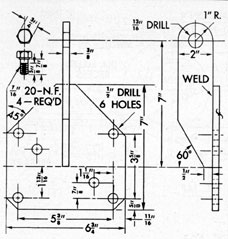
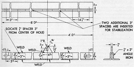
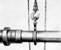
4A2. Shipping, unpacking, and handling. A
modern submarine periscope with a reduced section of small diameter is a fragile instrument, especially during handling and shipment. It is
shipped in a box of sturdy construction, but to
prevent needless stresses it is advisable that the
box, whenever possible, be hoisted or supported
at more than one point, preferably the quarter-points. During rail shipment, the box should be
securely chocked in the car. A reach truck is desirable for highway movement, and in any case
the box should be loaded so that the portion overhanging the truck contains the upper, lighter end
of the periscope. The name plate of the shipping
box is placed at the end containing the lower
heavier portion of the periscope.
The periscope is secured in the box by chocks,
with brass clamps provided to prevent endwise
movement in the box. The clamps should remain
with the box for reuse. The cover of the box when
inverted, serves as a convenient support for the
instrument.
In case of reshipment of the periscope, care
should be taken to see that the brass clamps are
in place, and that all accessories are either
mounted on the instrument or secured inside the
box.
B. HEAD WINDOW AND OUTER HEAD
4B1. General description. The area of the head
window is as small as practicable. Its bezel frame
is secured by screws. These screws are of noncorrosive material. The head window and its
bezel frame are of sufficient strength to withstand an internal 150 psi hydraulic test or an external 300 psi hydraulic test.
In order to be sure that the head window does
not crack as a result of the temperatures to
which the instrument is subjected in service, the
upper 2 feet of the instrument are tested by being
immersed in water and heated to a temperature
of 150 degrees F. This temperature is maintained for at
least one-half hour. The upper 2 feet of the
instrument are then plunged into water of a temperature not more than 70 degrees F and allowed to remain for at least one-half hour. This test is made
after the final installation of the head window,
43
but before the optics are in place. Any further
adjustment of the head window necessitates a
repetition of this test after such adjustment has
been made. In Type II periscopes in which a
joint between the head and the taper section
must be broken when installing optics in the head,
this test may be made upon the head only.
In view of the shocks to which this part of the
periscope may be subjected in service, such as a
depth-charge attack, an ample margin of strength
beyond that necessary to withstand the specified
test is most desirable. This is especially true of
the head window itself.
The metallic seats for the head window, both
in the head and in the bezel frame, should be
scraped as necessary to give a true bearing. An
approved gasket is inserted between the head
window and its seat. Both in the design of the
head window, its securing device, and their final
assembly in the periscope, all possible precautions are taken to prevent setting up unequal
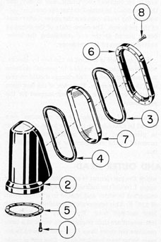
Figure 4-1. Outer head assembly.
strains in the glass caused by unevenness of the
seat, bezel frame, or gaskets, or by uneven setting
up of the securing device, or by other causes.
The inner circumference of the head window
bezel frame is beveled outward and away from its
line of contact with the glass. This increases the
effect of wind in clearing drops of water from the
glass and reduces the lodgment of water and
the deposit of salt by evaporation on the glass
near the inner circumference of the bezel frame.
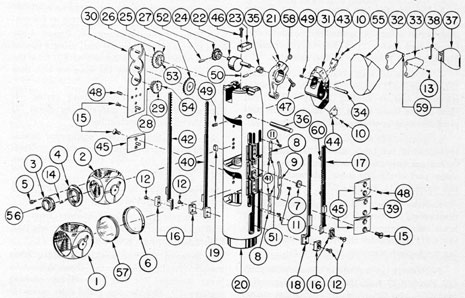
4B2. Outer head assembly. The outer head assembly is composed of the following parts, as
shown in Figure 4-1. All bubble numbers in Sections 4B2, 3, and 4 refer to Figure 4-1 unless
otherwise specified.
Ill. No.
Drawing Number
Num- ber Re- quired
Nomenclature
1
P-1389-2
12
Outer head seat lockscrews (lower)
2
P-1407-1
1
Outer head
3
P-1407-2
1
Head window bezel frame rubber gasket
4
P-1407-3
1
Head window seat rubber gasket
5
P-1407-4
1
Outer head seat rubber gasket
6
P-1409-8
1
Head window bezel frame
7
P-1418-1
1
Head window
8
P-1422-11
20
Head window bezel frame lockscrews
4B3. Description. a. Outer head. The outer
head (2) is made of corrosion-resisting steel material. It is designed to meet the service requirements of a covering for the upper part of the
skeleton head assembly. The bottom face is
counterbored to a nominal depth to accommodate the outer head seat rubber gasket (5). The
smaller counterbore is a push fit over a shoulder
of the outer taper section (1, Figure 4-15). The
machined recess in the outer head is at an angle
of 22 degrees from the vertical centerline. This recess
receives a head window seat rubber gasket (4)
and the head window (7).
The outer face of the outer head has 20 proportionately spaced 6-40 tapped holes to accommodate the head window bezel frame (6). This
frame is secured with 20 corrosion-resisting steel
lockscrews (8).
44
The bottom face, or seat, of the outer head
(2) has 12 equally spaced 4-48 tapped holes to
receive the lockscrews (1).
A recess of nominal depth, 3/8-inch width, and
5/8-inch length is machined in the rear inner wall
of the outer head to provide sufficient clearance
for the movement of the skeleton head eccentric
arm (21, Figure 4-17).
The inside wall of the outer head is provided
with approximately 0.010-inch clearance, so
that it does not touch any part of the skeleton
head mechanism when assembled to the outer
taper section (1, Figure 4-15).
b. Head window bezel frame. The head
window bezel frame (6) is made of phosphor-bronze material. Its lower face has a machined
irregular recess to fit over the head window (7)
with a 45 degrees angle. The 45 degrees angle of the beveled
recess is to accommodate a head window bezel
frame rubber gasket (3) which compresses to
the angle of the head window to form an airtight
seal.
The outer flange of the head window bezel
frame has 20 proportionately spaced clearance
holes with countersunk heads to accommodate
the lockscrews (8). These lockscrews extend into
tapped holes in the face of the outer head (2).
The inner irregular circumference of the head
window bezel frame is beveled outward at an
angle of 22 degrees away from the line of contact with
the glass.
c. Head window. The head window (7) is
made of one crown optical glass element with
parallel surfaces. It is molded with a 45 degrees angle
edge to which a head window bezel frame rubber
gasket (3) is applied. It provides a means of
sealing without obstructing the entering light
rays, and offers a transparent medium through
which light is transmitted.
4B4. Disassembly of the outer head. The outer
head is disassembled as follows;
1. Rotate the revolving grip of the left training handle assembly (2) so that the zero line of
sight graduation of the index ring (6) corresponds to the stationary index line graduation
of the fixed grip (29, Figure 4-43). This places
the head prism at zero line of sight, offering no
obstruction for the removal of the outer head,
and preventing damage to the head prism (55).
Check the right training handle; it should be set
for low power.
2. Remove the AIR OUTLET plug (14,
Figure 4-29) and open the AIR OUTLET valve
(16) of the eyepiece box (11) to allow the internal
gas pressure to be released slowly.
3. Remove the putty from the 12 countersunk holes at the upper part of the outer taper
section flange (1, Figure 4-15). This putty covers
up the screw heads and permits only personnel
familiar with the instrument to break the seal
of the periscope.
4. After the nitrogen pressure is released,
close the AIR OUTLET valve (16) and replace
the AIR OUTLET plug (14, Figure 4-29).
5. Remove the 12 lockscrews (1) from the
upper flange of the outer taper section (1,
Figure 4-15).
6. Remove the outer head assembly from the
outer taper section (1, Figure 4-15) by slowly
pulling off the outer head.
7. Remove the outer head seat rubber
gasket (5) from the outer taper section shoulder
(1, Figure 4-15).
8. Slack off each of 20 head window bezel
frame lockscrews (8) several turns.
9. Assemble the outer head seat rubber
gasket (5) and the outer head (2) to a special jig
with about six lockscrews (1). Apply an internal
air pressure of 15 to 30 psi to the outer head
assembly to break the seal of the head window
(7).
10. Remove the outer head assembly from the
special jig.
11. Remove the 20 head window bezel frame
lockscrews (8).
12. Lift the head window bezel frame (6)
off the outer head (2).
13. Push out the head window (7), placing a
piece of clean lens tissue on its bottom face.
The lens tissue is applied from the lower base
opening of the outer head (2).
14. Remove the head window seat rubber
gasket (4) from the seat of the outer head (2)
and destroy it.
45
4B5. Reassembly of the outer head. The outer
head is reassembled as follows:
1. Scrape the seat of the-outer head, if necessary, to give a true bearing. Mark the head
window (7) in the position it is scraped so that
it cannot be turned end-for-end.
2. Insert the new head window seat rubber
gasket (4) of crude rubber of specified drawing
dimensions into the head window seat of the
outer head (2).
3. Scrape the beveled seat of the head window bezel frame (6), if necessary, to provide a
true bearing surface in conjunction with the
beveled edge of the head window (7).
4. Clean the inner surface of the head window (7) with clean lens tissue, and use a small
air bulb to blow off surface dust.
5. Place the head window (7) in the head
window seat of the outer head (2) on the head
window seat rubber gasket (4).
6. The head window bezel frame rubber
gasket (3) should be approximately 0.072 inch
larger than the head window outer irregular
circumference, except to comply to drawing
dimension as to thickness. Place it in the head
window bezel frame (6) in one solid piece.
Punch a small hole in the center of the rubber
gasket to enable the trapped air to escape.
7. Place the head window bezel frame (6)
with the head window bezel frame rubber gasket
(3) over the head window (7). Insert the four
lockscrews (8) into the tapped holes in the flange
of the outer head, and screw each lockscrew
down flush with the head window bezel frame.
8. Place a flat wooden block 1 inch thick and
slightly smaller than the inner circumference
of the head window bezel frame (6) over the
head window bezel frame rubber gasket (3).
Place a C-clamp over the wooden block and the
outer head to flatten the raised center portion
of the rubber gasket. Use a wooden wedge on the
opposite side of the outer head to tighten the
clamp evenly. The flattening of the rubber
gasket forces the outer edges to adhere to the
inner beveled walls of the head window bezel
frame (6), and utilizes the entire area of the
beveled surface of the head window bezel frame
to maintain the seal.
9. Lubricate the threads of the head window
bezel frame lockscrews (8) lightly with a medium
grease before insertion, and tighten them evenly.
Take each lockscrew down equally in a series of
all-around adjustments and use a feeler gage as
a check around the head window bezel frame (6).
10. It is desirable to wet the head window
bezel frame rubber gasket (3), thereby providing
a lubricant for the brass knife-edge, when cutting
the crude rubber gasket around the inner
irregular circumference of the head window
bezel frame (6). The brass blade does not scratch
the head window surface.
11. Clean the outer surface of the head window
in the same manner as outlined in Step 4 of this
section,
12. Use a lens strain testing device to insure
that unequal strain is not placed on the head
window (7).
13. The outer head seat rubber gasket (5)
and the outer head (2) are not assembled to the
outer taper section (1, Figure 4-15) with lockscrews (1) until complete disassembly, assembly,
and collimation of the instrument have been
completed.
C. REMOVING INNER TUBE
4C1. Disassembly of the inner tube from the outer
tube. The inner tube is removed from the outer
tube as follows:
1. Place the periscope on V-blocks of the
optical I-beam bench. Place it so that sufficient
space remains to permit removal of the inner
tube.
2. Remove the four axial alignment screws
(48, Figure 4-17) located in the small shoulder
of the upper part of the outer taper section (1,
Figure 4-15). Unscrew them from the skeleton
head (20, Figure 4-17) and the outer taper
section. Place these lockscrews, in a small box.
3. Remove side plate and pressure gage lockscrews (5, Figure 4-29) from both sides of the
eyepiece box (11). It may be necessary to tap
out two diagonally opposite holes with an 32
tap in the side plate (9) and the pressure gage
46
assembly (21) for the insertion of special lockscrews to break the seal of the rubber gaskets
(10). Remove the two rubber gaskets (10).
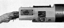
Figure 4-2. Special cord attached to shifting wire
spindles and held with both hands.
4. Using two pieces of special cord of 3-foot
length doubled, secure one end of each piece of
cord to the spindles (1, Figure 4-28) of the power
shifting side, and secure the other two loose ends
to the spindles (1) of the prism shifting side.
Take special care that the end of one cord is
secured to the left spindle (1) of the power
shifting side, while the other end is secured to
the right spindle (1) of the prism shifting side
(Figure 4-2). The second piece of cord is secured
in like manner to permit one man to hold one
set of shifting wire spindles (1) with one hand,
while the other set of spindles (1, Figure 4-28)
a held with the other hand, using the looped
cords.
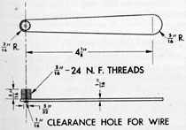
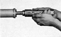
Figure 4-3. Special spindle adjusting nut adapter.
5. By means of a special spindle adjusting
nut removal adapter (Figure 4-3) remove the
four shifting wire spindle adjusting nuts (4,
Figure 4-28) one by one. The adapter has a short
threaded stem which has a clearance hole through
its center axis. The clearance hole permits the
adapter to be carried over the shifting wire (38)
up to the shifting wire spindle adjusting nuts (4).
Each lower adjusting nut (4), when removed
from the shifting wire spindle (1), is turned onto
the short threaded stem of the adapter. This
permits each adjusting nut (4) to be lifted out
through the side plate (9) opening of the eyepiece
box (11, Figure 4-29). The skeleton head
assembly is to be withdrawn (Figure 4-4) sufficiently to expose the clamp blocks (16, Figure
4-17) and remove it from the outer taper section
(1, Figure 4-15).
6. Remove the shifting wire tape (38, Figure 4-28) from the clamp blocks (16, Figure 4-17)
removing and replacing the clamp blocks (16)
and clamp block lockscrews (12) to the prism and
cube shifting racks (40, 42, 17, and 18) of the
skeleton head assembly.
Figure 4-4. The skeleton head assembly is withdrawn.
7. Before proceeding, it is necessary to secure
the tapes in place. This is done by using a special
metal dowel 1 inch in diameter (Figure 4-5) to
which the tapes are tightened sufficiently to pull
the dowel into contact with the ninth reduced
tube section. (1, Figure 4-18). A larger dowel will
not pass through the outer taper section (1, Figure 4-15) while a smaller one may rest on the
auxiliary upper eyepiece lens (5, Figure 4-18), in
the upper part of the ninth reduced tube section
and damage it.
8. After the tapes (38, Figure 4-28) are
tightened to the 1-inch metal dowel, and pulled
down into contact with the ninth reduced tube
section (1, Figure 4-18) by means of the looped
cords, the shifting wire spindles (1, Figure 4-28)
are free of the prism and power shifting racks
(43, 44, 45, and 46) of the eyepiece skeleton
assembly.
47
Figure 4-5. One-inch metal dowel, detail drawing.
9. Turn the stadimeter handwheel (12, Figure 4-24) to the observing position as noted by
the stamped numerals on the stadimeter housing
(67). The number 58 on the height scale dial (52)
should appear approximately opposite the value
2.2 on the range scale dial (50). Values opposite
58 and 2.2 will be found in Figure 2-12. This will
make possible the correct and rapid reassembly
of the stadimeter housing assembly. Remove the
four stadimeter housing bolts (30, Figure 4-24)
and take off the stadimeter housing assembly
with care to prevent bending the stadimeter
transmission shaft (22, Figure 4-27). An automatic stop prevents rotation of the stadimeter
handwheel (12, Figure 4-24) when not in place.
10. Remove the training handles by taking out
the eight hinge bracket bolts (19 and 21, Figures
4-43 and 4-44, respectively) for the left and right
training handle assemblies.
11. Remove the focusing knob assembly by
taking out the four lockscrews (10, Figure 4-39).
12. Remove the rayfilter by pulling outward
on both spring-actuated plunger knobs (24, Figure 4-40).
13. Remove the eyepiece attachments that are
secured to the anchor screw pins (19, Figure
4-29) projecting from the eyepiece box itself.
14. The hoisting yoke assembly is disassembled in the following manner (Figure 7-26)
a. Remove the covering lockscrews (4).
b. Unscrew the cover ring (2) with a spanner
wrench. Remove the hoisting yoke body (1),
phosphor-bronze locating collar (9), lower ball-bearing race (8), ball bearings and retainer (7),
and the upper ball-bearing race (6).
c. Remove the split ring (3). All parts of the
thrust bearing should be protected from dirt or
grit.
d. Remove the cover ring (2).
15. Rotate the periscope on the V-blocks of
the Optical I-beam bench so that the eyepiece
end is down.
Figure 4-6. Shifting wire tapes attached to 1-inch
metal dowel.
48
Figure 4-7. Eyepiece box and outer tube alignment guides.
16. Place the special outer tube alignment
guide on the outer tube over the undercut section. Using a socket wrench, secure it so that the
slotted section is lined up temporarily to the rear
vertical azimuth line of the outer tube (Figure
4-7). Place the eyepiece box alignment guide over
the two flat side portions of the eyepiece box (11,
Figure 4-29), resting it on the front flat portion.
Assemble the radius clamp (Figure 4-7) from the
Figure 4-8. Eyepiece box and outer tube alignment
guide handles in contact.
rear side of the eyepiece box (11, Figure 4-29)
to the two bolt projections of the eyepiece box
alignment guide. Check the outer tube and eyepiece box alignment guide handles to ascertain
their contact (Figure 4-8). Should any separation
be detected, loosen the outer tube alignment
guide bolt with the socket wrench and rotate its
handle in contact with the eyepiece box alignment guide handle and secure it. The purpose of
this outer tube and the eyepiece box alignment
guides is to establish correct entry and removal
guidance for the angular alignment key (1) in the
eyepiece box (11, Figure 4-29), with the keyway
in the lower part of the outer tube (2, Figure
4-15).
17. Remove the two lockscrews (7, Figure
4-29) in the main coupling (2) at the eyepiece
box (11). Unscrew the main coupling (2), using
a special spanner wrench. The main coupling (2)
has a right-hand thread on the outer tube and
a left-hand thread on the eyepiece box (11).
18. Attach a steel lifting plate (Figure 4-9) to
the base of the eyepiece box (11, Figure 4-29)
and insert four bolts in the clearance holes in the
steel lifting plate and the tapped holes in the
49
Figure 4-9. Steel lifting plate, detail drawing.
Figure 4-10. Chain hoist hook in shackle attached to
lifting plate.
Figure 4-11. Adjustable roller stand placed under eyepiece box.
50
Figure 4-12. Hinged clamp, detail drawing.
eyepiece box. Secure the steel lifting plate to the
eyepiece box base (11).
19. Attach a shackle to the lifting projection
of the steel lifting plate, and insert the hook of
the chain hoist (Figure 4-10). Apply a light lifting strain to this end of the eyepiece box.
20. Slowly pull the inner tube section out of
the outer tube until the lower (split) objective
lens coupling sleeve (34, Figure 4-23) is clear of
the outer tube. The inner tube must be guided
parallel to the outer tube and properly centered
in it.
Figure 4-13. Lifting spreader bar, detail drawing.
51
21. Place the adjustable roller stand (Figure
4-11) under the eyepiece box, removing the hook
of the chain hoist and the shackle.
22. Attach and secure the hinged clamp (Figure 4-12) over the lower (split) objective lens
coupling sleeve (34, Figure 4-23). Locate this
hinged clamp at the upper part of the coupling
sleeve.
23. Connect the upper part of the lifting
spreader bar (Figure 4-13) to the lifting projection of the hinged clamp with a bolt. Connect the
lower part of the lifting spreader bar to the lifting
projection of the steel lifting plate with a bolt.
Place the hook of the chain hoist in the center
pad clearance hole of the lifting spreader bar.
24. Take a light strain with the chain hoist on
the lifting spreader bar, and remove the adjustable roller stand (Figure 4-11). Resume the removal of the inner tube slowly until the fifth
inner tube section (34, Figure 4-20) is clear of the
outer tube. The inner tube must be guided parallel with the outer tube and properly centered
in it.
25. Attach and secure another hinged clamp
(Figure 4-14) over the upper part of the fifth
inner tube section (34, Figure 4-20). Attach a
shackle in the hole of the lifting projection of the
hinged clamp, and with the hook of the chain
hoist placed in the shackle, take a light strain
with the chain hoist.
26. Resume the removal of the inner tube
slowly, checking to see that it is guided parallel
with the outer tube and properly centered.
Figure 4-14. Hinged clamp attached to fifth inner
tube section with shackle and inserted chain hoist
hook.
27. Transport the inner tube to the V-blocks
of the second I-beam bench. Remove both chain
hoist hooks, hinged clamps, and the steel lifting
plate.
28. Using canvas-covered galvanized cable
slings, each wrapped once around the outer tube,
remove the outer tube from the V-blocks of the
Optical I-beam bench with both chain hoists and
transport it to the periscope rack.
D. OUTER TAPER SECTION, OUTER TUBE, AND INNER TUBE ASSEMBLIES
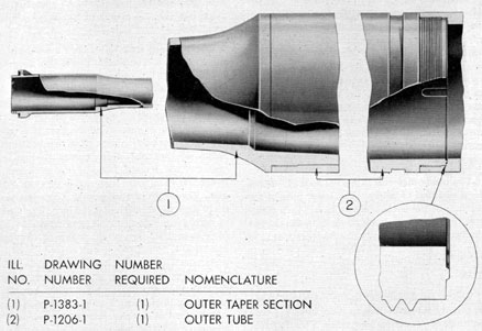
4D1. Outer taper section. The outer taper section (1, Figure 4-15) is made of solid forged corrosion-resisting steel. The external diameter of
the outer taper section is machined at the lower
end for a short distance. This short machined
distance serves as an alignment projection and
fits into the mating counterbored alignment support overlapping section of the upper part of the
outer tube. The threaded part of this machined
section (approximately 1 inch) has 12 threads per
inch, with a 1/16-inch relief to the large shoulder.
This portion is secured in the internal threads of
the counterbore, and has a sliding fit of 0.004
inch. Litharge and glycerin are coated over the
threads to maintain the seal as a permanent
joint.
The outer taper section shoulder has a width
of 1/2 inch. From this shoulder, the outer taper
section is machined at a radius for a short
distance to a diameter of 5 5/8 inches. It then
tapers to a diameter of 1 3/4 inches in a distance
of 37 inches. From this point, it tapers to a
diameter of 1.414 inches in 13 3/8 inches. It then
retains this diameter for a distance of 8 1/8
inches, at which point it is machined at a radius
to a diameter of 1.870 inches. This diameter remains constant for 3 3/16 inches, at which point
a 30 degrees chamfer of the upper flange of 2/12-inch
diameter remains.
The upper end of this flange section is machined with a shoulder which is a push fit in the
counterbored portion of the outer head (2,
Figure 4-1). The face of the flange is counterbored to a nominal depth to accommodate an
outer head seat rubber gasket (5), between the
flange and the outer head (2). In this
52
Figure 4-15. Outer taper section and outer tube, cross-sectional view.
counterbore, 12 equally spaced holes are provided to
accommodate lockscrews (1). The clearance
holes are countersunk from the lower end of the
radius of the flange.
The upper end of the machined 1.414-inch
section is counterbored a short distance with an
additional counterbored section to receive the
skeleton head assembly (Figure 4-17). A keyway,
0.032 inch deep and 0.124 inch wide, is provided
a short distance in the upper part of the counterbored wall. This keyway receives the angular
alignment key (19) of the skeleton head assembly and maintains its angular alignment.
Two tapped holes are provided on each side
in the overlapping shoulder that projects upward from the flange face. These four tapped
holes receive headless lockscrews (48), which retain the skeleton head assembly in the counterbore and extend into mating tapped holes in the
cube bracket (45) and the gear train bracket
(30) of the skeleton head assembly.
The inside diameter of the taper section does
not vary from the calculated diameter at any
point by more than +0.005 inch or -0.000 inch.
The bore of the taper is concentric with the
outside diameter within 0.005 inch.
The inside section of the lower end of the
outer taper section is chamfered at its lower
face at a 30 degrees angle. From this point, with a 6 3/8-inch diameter, it tapers upward to a diameter
of 5.560 inches in a distance of 6.752 inches, with
the shoulder chamfered to a diameter of 4.930
inches.
4D2. Outer tube. The outer tube (2, Figure
4-15) and the outer taper section (1) form the
outer shell of the periscope. It is machined
cylindrically to fit into a series of bronze steady
bearings of the submarine, and is bored cylindrically to receive the assembled inner tube
sections, which consist of a series of five telescope system assemblies (Figure 4-16).
The outer tube is machined from a solid forging of corrosion-resisting steel. It is 34 feet 1 inch
in length and finished to an outside diameter of
7.497 inches, plus 0.000 inch, minus 0.002 inch.
53
The upper part of the outer tube is counterbored a short distance, serving as an alignment
overlapping support for the alignment projection
of the outer taper section (1). The 1-inch
threaded portion of the alignment overlapping
support of 12 threads per inch has a 1/8-inch
relief to provide the external threads of the
alignment projection of the outer taper section
easy entry without crossing the threads. The
upper face is finished smooth to form a metal-to-metal contact with the lower shoulder face of the
outer taper section (1, Figure 4-15) when
assembled.
The inside diameter is ground to 6.375 inches
for a distance of 26 feet. The lower part of the
outer tube has a counterbore of 6 1/2-inch diameter for 7 feet, with a 15 degrees chamfer to the smaller
diameter. This partially counterbored section
provides sufficient clearance for the lower
(split) objective lens coupling sleeve (34, Figure
4-23).
The external diameter at the lower part has a
5/8-inch undercut section to a depth of 5/32 inch
on a side of the vertical centerline. This undercut
section starts 2 inches from the bottom face and
receives two split ring halves (3, Figure 7-26)
of the hoisting yoke assembly. The entire weight
of the periscope is carried by the hoisting yoke
assembled over the halves of the split ring (3).
The lower external part of the outer tube has
a turned shoulder with a threaded section of 12
threads per inch. The threaded section is relieved on each end with a slot, machined for a
width of 0.125 inch.
On the lower face of the outer tube, there is a
triangular annular ridge on the shoulder 1/64 inch
in height and approximately 1/16 inch in width
at the base. The angles, including the apex, are
filleted. The triangular annular ridge detail is
provided to compress a rubber gasket (8, Figure
4-29) into a corresponding triangular annular
groove in the large upper face of the eyepiece
box (11) joint shoulder. The compression of the
rubber gasket (8) into the triangular annular
groove of the eyepiece box (11) insures an airtight sealed joint.
A keyway of 3/8-inch width, 1/16-inch depth,
and length of 1 1/8 inch is provided in the inner
wall of the vertical centerline. This keyway
maintains the angular alignment with the eyepiece box (11) by means of the angular alignment key (1).
Two azimuth scale index lines are scribed on
the outer tube. The second line is 180 degrees from the
first line. Both lines lie in a plane passing through
the axis of the outer tube and coinciding approximately with the plane of sight through the
vertical centerline of the telemeter lens of the
periscope. These lines are in the form of grooves
of rectangular section with sides parallel to that
radius of the tube which passes through the
center of the groove. The width of each groove
is not less than 0.015 inch nor more than 0.020
inch. The depth of each groove is not less than
0.010 inch nor more than 0.015 inch. The center
of each groove does not, at any point, deviate
more than 0.003 inch to either side of a straight
line parallel to the axis of the outer tube of the
periscope. The angle between the plane in which
the grooves are situated and the plane of sight
through the vertical centerline of the telemeter
lens of the instrument is as small as practicable
and does not in any case exceed 15 minutes. The
grooves extend upward from the top of the
hoisting yoke groove along the outer tube for a
distance of 6 feet. In some periscopes the grooves
have been extended to a length of 22 feet above
the hoisting yoke groove.
Numbers are stamped or engraved on the
eyepiece side of the outer tube at intervals of 1
foot for a distance of 6 feet above the hoisting
yoke groove, showing the distance in feet from the axis of the line sight through the head
window of the periscope to the position of the
upper edge of each number. The left edge of the
left digit of each number is located 1/2 inch to
the right of the azimuth index line, each number
is at least 3/8 inch high and is stamped or engraved
to a sufficient width and depth as to be easily
visible to a person standing 5 feet away from the
periscope.
The steady bearings are placed in the submarine periscope supports at intervals to carry the
periscope vertically, and also to provide vertical
guidance. The periscope can be trained through
360 degrees of azimuth, and raised and lowered.
The raising and lowering are accomplished
by one of two systems, electric or hydraulic.
With the electric hoisting system, the wire ropes
54
are attached to the hoisting yoke. The wire ropes
in turn are carried over pulleys to a cable drum,
which is operated by an electric motor. Safety
cutout switches are provided to cut off the power
when the periscope is at the limit of the vertical
travel at the observing position or at the lowered
position.
With the hydraulic hoisting system, the
plunger rods are attached to the bracket connectors secured to the hoisting yoke. The
hydraulic control valve controls the raising and
lowering of the periscope by means of the ship's
hydraulic system under high pressure. A safety
limit stop serves to cut off the hydraulic pressure
when the periscope is at the limit of the vertical
travel or the observing position. The weight of
the periscope causes the hydraulic pistons to act
on the volume of oil in the low-pressure side of
the system, and the friction of the oil in the
return piping to control the lowering of the periscope. No limit stop is provided in lowering the
periscope. The precautions to be taken when
elevating and lowering a periscope are:
1. Notify men working around the vicinity to
stand clear.
2. Remove the cover plate (if fitted) over the
top steady bearing of the submarine.
4D3. Inner tube assemblies.Figure 4-16 shows
the inner tube of the periscope divided into five
telescope systems. Each telescope system is made
up of assemblies as follows:
1. Galilean telescope system: skeleton head
assembly.
Part I. First reduced tube section and fifth
and sixth inner tube sections.
Part II. Second, third, and fourth inner tube
sections.
5. Lower main telescope system.
a. Lower (split) objective lens and mount
assembly.
b. Objective operating mechanism assembly.
c. First inner tube section assembly.
d. Eyepiece skeleton assembly.
e. Eyepiece box and miscellaneous assemblies.
1) One stadimeter transmission shaft packing
gland assembly, and four spring-loaded packing
gland assemblies.
2) Eyepiece window frame assembly.
f. External projections to the eyepiece box.
1) Stadimeter housing assembly.
2) Focusing knob assembly.
3) Rayfilter assembly.
4) Eye buffer and blinder assembly.
5) Variable density polaroid filter assembly.
6) Training handle assemblies.
7) Hoisting yoke assembly.
E. SEPARATION OF THE FIVE TELESCOPE SYSTEMS
4E1. Separation of the Galilean telescope system.
1. The Galilean telescope system is located in
the skeleton head assembly. It has already been
disassembled from the upper end of the outer
taper section (1, Figure 4-15).
2. Remove the prism and power shifting tapes
(38, Figure 4-28) by slacking off the four shifting
wire clamps (2) of the eyepiece skeleton assembly. Remove them from the reduced tube and
inner tube sections.
4E2. Separation of the auxiliary upper telescope
system. This consists of the seventh, eighth, and
ninth reduced tube section assembly.
1. Remove the four lockscrews (16, Figure
4-18) from the lower part of the seventh reduced
tube section (14). These lockscrews are unscrewed from tapped holes in the upper part of
the sixth reduced tube section (1, Figure 4-19).
2. Unscrew the lower part of the seventh reduced tube section (14, Figure 4-18) from the
55
upper part of the sixth reduced tube section (1,
Figure 4-19).
4E3. Separation of the auxiliary lower telescope
system. This consists of the second, third, fourth,
fifth, and sixth reduced tube section assembly.
1. Remove the two lockscrews (22, Figure
4-19) from the removable air line strap (21) and
remove the air line strap. These lockscrews are
unscrewed from tapped holes in the second reduced tube section (19).
2. Pull the air line section (18, Figure 4-20)
outward to disconnect the air line coupling (14)
and remove the air line section (18) from the air
line adapter (11, Figure 4-19) and the attached
coupling (14, Figure 4-20) from the bent air line
section (17).
3. Remove the four lockscrews (8) from the
upper part of the first reduced tube section (1).
These lockscrews are unscrewed from tapped
holes in the second reduced tube section (19,
Figure 4-19).
4. Unscrew the second reduced tube section
(19) from the first reduced tube section (1, Figure 4-20). The second, third, fourth, fifth, and
sixth reduced tube sections are removed together.
4E4. Separation of the upper telescope system.
This consists of two assemblies, Parts I and II.
1. Remove the two lockscrews (22, Figure
4-20) removing the removable air line strap (19)
from the lower part of the first reduced tube
section (1). Remove the bent air line (17) from
this reduced tube section, carrying with it the air
line coupling (15) and short air line section (16)
from the upper opening of the soldered air line
section (30) of the sixth inner tube section (23).
2. Remove the air line section (31) from the
lower opening of the soldered air line section (30)
of the sixth, inner tube section (23) and the upper
opening of the soldered air line section (10) of the
fourth inner tube section (1, Figure 4-21).
3. Remove the air line section (21) pulling it
outward to free it from the lower part of the
soldered air line (10) of the fourth inner tube
section (1) and removing it from the upper part
of the soldered air line section (20) of the third
inner tube section (11).
4. Remove the four lockscrews (35, Figure
4-20) from the lower part of the fifth inner tube
section (34). These lockscrews are unscrewed
from tapped holes in the fourth inner tube section upper end coupling (5, Figure 4-21).
5. Remove the fifth inner tube section (34,
Figure 4-20) unscrewing it from the upper part
of the fourth inner tube section upper end coupling (5, Figure 4-21).
6. Remove the two lockscrews (32) from the
removable air line strap (30) and remove the air
line strap from the lower part of the second inner
tube section (22). These lockscrews are unscrewed from tapped holes in the second inner
tube section.
7. Remove the two lockscrews (24, Figure
4-27) from the removable air line strap (21) and
remove the air line strap from the upper part of
the first inner tube section (1).
8. Lift up both air line sections (29 and 18,
Figures 4-21 and 4-27 respectively) sufficiently to
remove the air line section (29, Figure 4-21) and
the soldered air line coupling (28) from the air
line section (18, Figure 4-27) of the first inner
tube section (1), and remove the air line section
(29, Figure 4-21) from its connection with the
lower opening of the soldered air line section (20)
of the third inner tube section (11).
9. Slide the air line section (18, Figure 4-27)
upward to disconnect the air line coupling (17)
from the bent air line section (16) located at the
lower end of the first inner tube section (1).
10. Remove the two lockscrews (24) from the
removable air line strap (19) and remove the air
line strap from the lower part of the first inner
tube section (1).
11. Remove the bent air line section (16) from
its connection with the long air line coupling (15).
12. Unscrew the long air line coupling (15)
from the flange of the eyepiece skeleton (42, Figure 4-28).
13. Remove the 15 lockscrews (27, Figure
4-23) from the lower part of the lower (split) objective lens coupling sleeve (34). These lockscrews are unscrewed from tapped holes in the
large flange section of the track sleeve (2).
14. Slide the lower telescope system assembly
clear of the coupling sleeve (34) about a foot.
15. Remove the four lockscrews (22) from the
upper part of the lower (split) objective lens
coupling sleeve (34). These lockscrews are unscrewed from tapped holes in the lower part of
56
the second inner tube section lower end coupling
(26, Figure 4-21).
16. Remove the split-objective lens coupling
sleeve (34, Figure 4-23) unscrewing it from the
lower part of the second inner tube section lower
end coupling (26, Figure 4-21) and remove the
second, third, and fourth inner tube section
assembly.
4E5. Separation of the lower telescope system.
The lower telescope system is broken into assemblies in the following manner:
1. Remove the two stadimeter collimating
lockscrews (13, Figure 4-22) and washers (14)
from each of the lower (split) objective lens and
mount assembly halves. These lockscrews are unscrewed from tapped holes in each mounting
plate half (5, Figure 4-23) of the objective operating mechanism assembly. The straight dowel pins
(15, Figure 4-22) are carried out with the mounts
(1 and 2) from the mounting plates (5, Figure
4-23).
2. Remove the taper pin (33) from the upper
part of the stadimeter transmission shaft coupling (14).
3. Remove the two taper pins (10, Figure
4-27) from the two stadimeter transmission
shaft thrust collars (4) located on the stadimeter
transmission shaft (22) on each side of the spider
(2) of the first inner tube section assembly.
4. Remove the stadimeter transmission shaft
(22, Figure 4-27) sliding it out of the stadimeter
transmission shaft coupling (14, Figure 4-23) and
clear of the track sleeve (2). Remove this coupling from the operating gear pinion shaft (13).
5. Remove the four lockscrews (23) from the
lower end of the track sleeve (2). These lockscrews are unscrewed from tapped holes in the
upper part of the first inner tube section upper
end coupling (11, Figure 4-27).
6. Remove the track sleeve (2, Figure 4-23),
unscrewing it from the upper part of the first
inner tube section upper end coupling (11, Figure 4-27) and remove the split-objective operating mechanism assembly (Figure 4-23).
7. Remove the stadimeter transmission shaft
(22, Figure 4-27) from the first inner tube section
assembly, also removing the two thrust collars
(4) from each side of the spider bearing projection (2).
8. Check reference marks on all four spring-loaded packing gland assemblies with corresponding reference marks of the eyepiece box (11, Figure 4-29).
9. Remove the six lockscrews (1, Figure 4-36)
from the stuffing boxes (5) for the left and right
training handle assemblies, and the six lock
screws (3, Figure 4-35) from the stuffing box (6)
for the eyepiece drive packing gland assembly.
10. Remove the four lockscrews (13, Figure
4-32) from the stuffing box (4) for the rayfilter
packing gland assembly.
11. Remove the eyepiece drive and the left and
right training handle packing gland assemblies
(25 and 26, Figure 4-29) using a special packing
gland wrench. Place this wrench over the square
section of each shaft. Using a sideward thrust
movement, remove the assemblies.
12. Remove the rayfilter drive actuating gear
(11, Figure 4-32) from the protruding square
section of the rayfilter drive actuating shaft
(10). Remove the rayfilter drive packing gland
assembly by placing a pair of parallel pliers over
the square section of this shaft, and, using a
slight sideward thrust, pulling outward.
13. Disassembly of the spring type stadimeter
transmission shaft assembly proceeds as follows:
a. Remove the lockscrew (1, Figure 4-30)
from the spring retainer (3) and, using a special
wrench, unscrew the spring retainer (3) from the
stuffing box chamber in the eyepiece box base
(11, Figure 4-29).
b. Remove the packing gland spring (4,
Figure 4-30), packing, and packing gland (2)
from the stuffing box chamber.
14. Where the modified stadimeter transmission shaft packing gland assembly is utilized,
delete Step 13 and follow the disassembly procedure as follows:
a. Remove the lockscrew (1, Figure 4-31)
from the packing retainer (2).
b. Unscrew the packing retainer from the
stuffing box section in the eyepiece box (11,
Figure 4-29) using a special wrench.
c. Remove the one packing retainer brass
washer (6, Figure 4-31) the three separation
brass washers (5), the four Hycar packing
washers (4), and the one gland filler piece (3)
from the stuffing box chamber in the eyepiece
box base (11, Figure 4-29).
57
15. Remove the seven lockscrews (19, Figure
4-40) from each side of the rayfilter plate (2).
These lockscrews are unscrewed from tapped
holes in both rayfilter plate straps (3). Remove
the rayfilter plate (2) and two rayfilter plate
straps (3).
16. Remove the four short and eight long
lockscrews (2 and 3, Figure 4-38) from the eyepiece window frame (7) of the eyepiece window
assembly. These lockscrews are unscrewed from
tapped holes in the counterbored recess face in
the eyepiece box (11, Figure 4-29). Remove this
assembly from the eyepiece box.
17. Remove the eyepiece lens mount (19,
Figure 4-28) by unscrewing it from the eyepiece
prism front retaining plate (24) attached to the
eyepiece prism mount (20). The eyepiece lens
mount (19) contains the eyepiece lens (52), eyepiece lens clamp ring (16), and its lockscrew (41).
18. Move the counterweight to its extreme
upper position in order to have sufficient space
for removal of the eight lockscrews (31). Remove
these lockscrews from the upper face of the
eyepiece skeleton flange. These lockscrews are
unscrewed from the tapped holes of the upper
face of the eyepiece box (11, Figure 4-29).
19. Remove the eyepiece box (11) from the
eyepiece skeleton (42, Figure 4-28) carrying it
off from the lower end.
20. Move the counterweight to its extreme
lower position in order to remove the four lockscrews (37) from the cylindrical bearing surface
in the upper part of the eyepiece skeleton (42).
These lockscrews are unscrewed from tapped
holes in the spider bearing (3, Figure 4-27) of the
first inner tube section assembly.
21. Remove the upper part of the eyepiece
skeleton (42, Figure 4-28), unscrewing it from the
lower part of the spider bearing (3, Figure 4-27).
F. GALILEAN TELESCOPE SYSTEM
4F1. Description of the skeleton head assembly.
Figure 4-17 shows the skeleton head assembly.
All bubble numbers in Sections 4F1, 2, and 3
refer to Figure 4-17 unless otherwise specified.
Figure 4-17. Skeleton head assembly.
58
Ill. No.
Drawing Number
Num- ber Re- quired
Nomenclature
1
P-1306-7
1
Galilean objective lens cube
2
P-1306-8
1
Galilean eyepiece lens cube
3
P-1306-9
1
Galilean eyepiece lens mount
4
P-1306-10
1
Galilean eyepiece lens mount housing
5
P-1306-11
3
Galilean eyepiece lens mount housing lockscrews
6
P-1306-12
1
Galilean objective lens retainer
7
P-1308-10
1
Power shift gear
8
P-1308-16
2
Pawl holders
9
P-1308-17
1
Reinforcing spring
10
P-1310-5
8
Head prism mounting clamp lockscrews
11
P-1310-6
6
Pawl holder and reinforcing spring lockscrews
12
P-1310-7
8
Clamp block lockscrews
13
P-1310-8
4
Head prism side plate lockscrews
14
P-1310-12
1
Galilean eyepiece lens mount lockscrew
15
P-1310-37
12
Various bracket lockscrews
16
P-1315-3
4
Clamp blocks
17
P-1315-4
1
Cube shifting rack (right)
18
P-1315-5
1
Cube shifting rack (left)
19
P-1383-2
1
Angular alignment key
20
P-1385-1
1
Skeleton head
21
P-1386-1
1
Eccentric arm
22
P-1386-2
1
Eccentric shaft
23
P-1386-3
2
Bearing caps
24
P-1386-4
1
Head prism shift actuating gear
25
P-1386-5
1
Fourth intermediate head prism shift gear
26
P-1386-6
1
Third intermediate head prism shift gear
27
P-1386-7
1
Second intermediate head prism shift gear
28
P-1386-8
1
First intermediate head prism shift gear
29
P-1386-9
1
Head prism shift gear
30
P-1386-10
1
Gear train bracket
31
P-1387-1
1
Head prism mount
32
P-1387-2
1
Head prism side plate (left)
33
P-1387-3
1
Head prism side plate (right)
34
P-1387-4
1
Eccentric arm pin
35
P-1387-5
1
Eccentric shaft collar
36
P-1387-6
1
Head prism mount pivot shaft
37
P-1387-7
1
Head prism shade
38
P-1387-8
2
Head prism shade wire links
39
P-1388-1
1
Power shift gear bracket
40
P-1388-2
1
Head prism shifting rack (left)
41
P-1388-3
2
Power shift pawls
42
P-1388-4
1
Head prism shifting rack (right)
Ill. No.
Drawing Number
Num- ber Re- quired
Nomenclature
43
P-1388-6
2
Head prism mounting clamps (left)
44
P-1388-7
2
Head prism mounting clamps (right)
45
P-1388-8
3
Cube brackets
46
P-1389-1
4
Split bearing cap lockscrews
47
P-1389-2
1
Eccentric arm adjusting screw
48
P-1389-3
4
Axial alignment lockscrews
49
P-1389-4
2
Eccentric arm pin lockscrew and head prism base shaft lockscrew
50
P-1389-175
1
Eccentric shaft collar taper pin
51
P-1389-176
4
Rivets for pawl holders and pawls
52
P-1389-177
1
Prism shift actuating gear taper pin
53
P-1389-178
2
Third and fourth intermediate prism shift gear rivets
54
P-1389-179
2
First intermediate and prism shift gear rivets
55
P-1418-2
1
Head prism
56
P-1418-3
1
Galilean eyepiece lens
57
P-1418-4
1
Galilean objective lens
58
1
Eccentric arm spacer washer
59
4
Head prism shade wire link, rivets, attached to head prism side plates and shade
60
2
Right cube shifting rack pins
a. Skeleton head frame. The skeleton head
frame (20) is machined of phosphor-bronze
material. It forms the necessary framework to
carry the prism tilt mechanism, Galilean telescope, and change of power mechanism. The
skeleton head is a push fit in the counterbored
section in the upper 1.890-inch section of the
outer taper section (1, Figure 4-15).
The prism tilt mechanism is composed of
numerous mechanical parts in the upper and
left hand side of the skeleton head to operate one
optical element, the head prism (55).
b. Head prism. The head prism (55) is a
right angle prism made of dense flint optical
glass material. It is used to reflect the light rays
at right angles. The light rays enter from any
position of elevation between 90.5 degrees to 26 degrees depression in low power and from 78.5 degrees elevation
to 14 degrees depression in high power, and are deflected
downward into the instrument.
59
c. Head prism mount. The head prism
mount (31) carries the head prism (55) with
a suitable clamping arrangement. The base
bearing provision of the mount fits between
two machined shoulders of the upper part of the
skeleton head and pivots over the head prism
mount pivot shaft (36). Above the base bearing
provision, a recess is provided for the insertion
of the extended arm bearing section of the eccentric arm (21), attached to the mount with an
eccentric arm pin (34) and secured to the mount
with a headless lockscrew (49). The skeleton
head frame is provided with recesses to allow
clearance for the eccentric arm and the head
prism mount (31) for all degrees of elevation
and depression. The head prism (55) is retained
from sideward movement with two head prism
side plates left and right (32 and 33), and it is
held to the head prism mount (31) with two
pairs of head prism mounting clamps (43 and 44)
secured with two lockscrews each (10).
d. Head prism side plates. The head prism
side plates left and right (32 and 33) are attached to the head prism mount (31) with two
lockscrews (13) each. These side plates retain
the head prism (55) from sideward movement.
Attached to each side plate are two head prism
shade wire links (38) secured with rivets (59).
The opposite ends of each wire link are secured
to each bent-over side of the head prism shade
(37), so that the shade is carried vertically with
the movement of the head prism mount (31).
e. Head prism shade. The head prism shade
(37) is made of sheet brass material, and is
constructed to conform with the contour of the
skeleton head periphery. The sides are bent
downward and again at 90 degrees to fit into a vertical
recess groove in each of the inner side walls of
the skeleton head. Wire links (38) are attached
with rivets (59) to each bent side of the shade.
As the head prism (55) is elevated or depressed,
the head prism shade is carried vertically and is
used principally in the elevated position to
shade the lower 90 degrees face of the head prism (55),
thus preventing a double image.
f. Eccentric arm. The eccentric arm (21) is
made of cast phosphor-bronze material. The
large section has a reamed hole with a stub section having a sawed slot, and fits over the eccentric of the eccentric shaft (22). The stub section
is provided with a spacer washer (58) fitted in the
sawed slot. The front half of the stub section has
a clearance hole with a countersunk section for
the eccentric arm adjusting screw (47). This adjusting screw extends into the tapped hole in the
opposite rear half of the stub section, and, with
the assembled spacer washer, allows only a sufficient sliding clearance over the eccentric of the
eccentric shaft (22). The eccentric arm (21) assembled to the eccentric shaft (22) actuates the
head prism (55) by means of the extended arm
bearing section assembled over the eccentric arm
pin (34) between the two recessed walls of the
head prism mount base (31) for elevation and
depression.
g. Eccentric shaft. The eccentric shaft (22)
is made of corrosion-resisting steel material. The
centerline of the eccentric is offset from both
shaft stems 0.179-inch. The offset provides the
necessary cam movement for the manipulation of
the head prism (55) to all the required degrees of
elevation and depression. Both of the eccentric
shaft stems fit into the lower reamed bearing
halves of the skeleton head (20) and are secured
radially with the upper two reamed bearing cap
halves (23). These bearing caps are secured with
two lockscrews (46) each. The axial displacement
of the eccentric shaft stems is secured individually
on each side. The right side has a thrust collar
(35) secured with a taper pin (50), while the left
side accommodates a head prism shift actuating
gear (24) which also is secured with a taper pin
(52). Both the thrust collar (35) and the head
prism shift actuating gear (24) are secured
snugly against the bearings in the milled recesses
of the skeleton head.
h. Head prism shift actuating gear. The
head prism shift actuating gear (24) is made of
phosphor-bronze material. The large diameter
has 20 teeth of nominal width around the outer
circumference, to mesh with the teeth of the
fourth intermediate prism shift gear (25). The
reamed hole of the actuating gear (24) is a push
fit on the stem section of the eccentric shaft (22)
and is secured with a taper pin (52) through the
hub section.
i. Fourth intermediate head prism shift
gear. The fourth intermediate head prism shift
gear (25) is made of phosphor-bronze material
and has 18 teeth around the outer circumference
which mesh with the teeth of the head prism
60
shift actuating gear (24). This intermediate head
prism shift gear (25) fits into a clearance hole of
the left side of the skeleton head (20). The
reamed hole in the center axis is a sliding fit over
the first integral upper pin projection of the gear
train bracket (30), with two number 60 drilled
holes for the insertion of rivets (53) to secure it
to the undercut shoulder side of the third intermediate head prism shift gear (26).
j. Third intermediate head prism shift
gear. The third intermediate head prism shift
gear (26) is made of phosphor-bronze material
and has 32 teeth around the outer circumference
which mesh with the teeth of the second intermediate head prism shift gear (27). This intermediate head prism shift gear (26) has a reamed
hole in the center axis which is a sliding fit over
the first integral upper pin projection and sets in
the shallow counterbored section in the gear
train bracket (30). It also is provided with two
number 60 drilled holes for the insertion of rivets
53) and is secured to the fourth intermediate
head prism shift gear (25) and riveted.
k. Second intermediate head prism shift
gear. The second intermediate head prism shift
ear (27) is identical to the third intermediate
bead prism shift gear (26) except in the diameter
of its undercut shoulder. The teeth mesh with the
first intermediate head prism shift gear (28). The
reamed hole in its center axis is a sliding fit over
the second integral upper pin projection and sets
in the countersunk recess of the gear train
bracket (30).
1. First intermediate head prism shift
gear. The first intermediate head prism shift
hear (28) is made of phosphor-bronze material,
and has 18 teeth around the outer circumference
which mesh with the second intermediate head
prism shift gear (27). This intermediate head
prism shift gear (28) has a reamed hole in the center axis which is a sliding fit over the second
integral lower pin projection and sets in the
countersunk recess of the gear train bracket (30).
It is also provided with two number 60 drilled
holes for the insertion of rivets (54) and is secured to the head prism shift gear (29) and
riveted.
m. Head prism shift gear. The head prism
shift gear (29) is made of phosphor-bronze material, and has 21 teeth around the outer circumference
which mesh with the gear teeth of the head
prism shifting racks left and right (40 and 42).
This head prism shift gear (29) has a reamed hole
in the center axis which is a sliding fit over the
second integral lower pin projection of the gear
train bracket (30) and sets inside the countersunk
recess of the skeleton head between both the head
prism shifting racks left and right (40 and 42). It
also is provided with two number 60 drilled holes
for the insertion of rivets (54) and is secured to
the first intermediate head prism shift gear (28)
and riveted.
n. Head prism shifting racks. The head
prism shifting racks left and right (40 and 42) are
made of blued, cold rolled steel, and operate in
vertical recess grooves. The left shifting rack (40)
is made of nominal width and thickness and is
provided with 22 gear teeth in the upper part of
the right side in a distance of 1.437 inches to
mesh with the teeth of the head prism shift gear
(29) on the left side. This shifting rack (40) is
offset to the right, and stepped inward toward
the center axis. The outer portion of the stepped
section is provided with a radius contour of
0.607 inch, and the inside portion has a 0.550-inch radius contour to conform to the counterbore of the skeleton head. The lower end has a
45 degrees radius chamfer conforming to a similar mating radius chamfer of the clamp block (16).
Two tapped holes are provided in the radius contour wall of the stepped section to accommodate
clamp block lockscrews (12). The flat monel
metal tape ends of the shifting wire tape (38,
Figure 4-28) of the eyepiece skeleton assembly
are secured to the outer radius contour of the
stepped section with the clamp blocks (16) and
the head prism shifting rack (40). This causes the
shifting wire tape (38, Figure 4-28) to be stepped
at 45 degrees bevel downward sufficiently to carry it
free in the inside radius groove of the skeleton
head. Above the stepped section on the outer
surface of the head prism shifting rack (40) a
protruding stop section of 0.375 inch is located
a distance of 1.125 inches from the lower end, and
its outer surface has a radius slightly below the
contour of the skeleton head periphery. The stop
section in contact with the cube bracket (45) restricts the movement of the head prism in the
elevated position to the designed limits, thus preventing any damage to the head prism (55) and
its operating mechanism.
61
The head prism shifting rack right (42) is similar to the left in design, except for the fact that
it is constructed in opposite manner. Its teeth
mesh with the teeth of the head prism shift gear
(29) on the right side. The integral stop section of
this head prism shifting rack (42) in contact
with the cube bracket (45) restricts the movement of the head prism in the depressed position
to its designed limit.
Both head prism shifting racks left and right
(40 and 42) fit into two vertical slots on each side
of the vertical centerline of the skeleton head
left side wall. Two vertical elongated holes below
the groove seats, and offset toward the vertical
centerline, provide clearance for the stepped sections of both head prism shifting racks and allow
for the attachment of the shifting wire tape (38,
Figure 4-28).
o. Gear train bracket. The gear train
bracket (30) is made of blued, cold rolled steel
material, and serves various functions. It serves
to carry the gear train of the first, second, third,
and fourth intermediate head prism shift gears
(28, 27, 26, 25) and the head prism shift gear
(29) by means of four pin projections integral
with the bracket. It provides a closed housing by
means of countersunk recesses below the three
integral upper pin projections for the 1st, 2nd,
and 3rd intermediate head prism shift gears (28,
27, and 26) and also serves as a retaining plate
for the upper part of the head prism shifting
racks left and right (40 and 42). The lower pin
projection serves as a pivot for the reamed hole
axis of the Galilean eyepiece lens cube (2). All
four integral pin projections are a sliding fit into
the reamed holes in the left side wall of the skeleton head. The bracket is secured to the flat recess face in the skeleton head with four lockscrews (15) located in the lower part. Two
tapped holes are located in the periphery of this
bracket on each side of the centerline in the lower
part to coincide with the tapped holes of the
overlapping section of the outer taper section (1,
Figure 4-15) to maintain the axial alignment of
the skeleton head with lockscrews (48). The periphery of the bracket when assembled on the
skeleton head conforms to its periphery.
p. Cube bracket. The cube bracket (45) is
made of blued, cold rolled steel material. It
serves to retain the lower part of the head prism
shifting racks (40 and 42). The pin projection,
an integral part of this cube bracket, serves as
the pivot for the reamed hole axis in the Galilean
objective lens cube (1). This integral pin projection is a sliding fit in the reamed hole in the
vertical centerline and is secured with two lockscrews (15) which are also located in the centerline on each side of the integral pin projection
securing the bracket to the fiat recess in the skeleton head. This bracket serves as a stop for each
stop of the head prism shifting racks (40 and 42)
for the elevation and depression position of the
head prism (55).
q. Angular alignment key. The angular
alignment key (19) is inserted in the vertical
centerline in the left side of the skeleton head
and is located in the center part. This key is a
sliding fit in the vertical keyway in the upper
part of the counterbore wall of the outer taper
section, and maintains the angular alignment of
the skeleton head (20).
The Galilean telescope system is composed of
two lenses; namely, a negative Galilean eyepiece
lens doublet and a positive Galilean objective
lens doublet. It is used in reverse to effect a low
power magnification and increase the true field
of view.
r. Galilean eyepiece lens. The Galilean eyepiece lens (56) is made of two optical elements,
one is a divergent meniscus flint element, cemented to the equi-concave crown element, forming a negative doublet. The divergent meniscus
element cemented to the equi-concave element
of the Galilean eyepiece lens corrects for spherical and chromatic aberration. It is mounted in a
Galilean eyepiece lens mount (3) and burnished
in place. The threaded mount can be screwed
vertically in the threads of the Galilean eyepiece
lens mount housing (4) by using a sharp pointed
scribe inserted in any one of a series of eight
shallow drilled recesses. This vertical movement
provides a means of focusing for elimination of
parallax.
s. Galilean eyepiece lens mount housing.
The galilean eyepiece lens mount housing (4) is
provided with an internal threaded bore to carry
the mounted Galilean eyepiece lens (56) and
mount (3) movement to eliminate parallax. The
housing flange has three equally spaced clearance
holes. One hole is used as a pivot hole, while the
62
other two are elongated for collimation. A tapped
hole located in the outer undercut shoulder receives the lockscrew (14) used to secure the
mounted Galilean eyepiece lens (56) and mount
after parallax removal.
t. Galilean eyepiece lens cube. The Galilean eyepiece lens cube (2) is constructed of a
suitable framework for holding the Galilean
eyepiece lens mount housing (4). By means of
integral pin projections of the cube bracket (45)
and the gear train bracket (30) protruding in
the reamed hole axis in opposite sides of the
cube, it can be rotated for change of power. The
undercut shoulder of 0.010-inch width and
0.437-inch diameter on each side face provides
sufficient bearing wall. All corners are rounded
off with a radius of 0.750 inch. The two 90 degrees
V-grooves in the right side wall located at 90 degrees,
receive the upper pawl (41) attached to the pawl
holder (8) with rivets (51). The pawls are held
in the grooves with a reinforcing spring (9) to
maintain the cube in either the IN or OUT position (low or high power). The 90 degrees rotation of the
cube is accomplished by the upper pin projection (60) of the right cube shifting rack (17),
protruding into the elongated slot in the right
side face. The clearance hole in the upper face
of the cube allows the lower undercut shoulder
sufficient free movement for collimation of the
Galilean eyepiece lens (56). Three equally spaced
tapped holes in the upper face receive lockscrews (5) to secure the Galilean eyepiece lens
mount housing (4) after collimation. The lower
wall is bored out and provided with antireflection threads, and also the front and rear walls,
thus offering no obstruction for the entering light
rays in either high or low power. The skeleton
head (20) is machined out, leaving only the side
walls and the center support to accommodate
sufficient clearance for the assembly, disassembly, and manipulation of this cube.
u. Galilean objective lens. The Galilean
objective lens (57) is made of two optical elements, consisting of a double convex flint element cemented to a divergent meniscus dense
crown element, forming a positive objective
lens doublet. It is mounted in the Galilean
objective lens cube (1) and secured with a
Galilean objective lens retainer (6). The retainer is spot soldered to the Galilean objective
lens cube (1) to prevent it from unscrewing.
v. Galilean objective lens cube. The Galilean objective lens cube (1) is constructed
similarly to the Galilean eyepiece lens cube (2).
The lower part is counterbored a shallow depth
to serve as a mount for the Galilean objective
lens (57), while its outer shoulder is threaded to
receive the internal threaded section of the
Galilean objective lens retainer (6). The upper,
front, and rear walls are bored and provided with
antireflection threads, thus offering no obstruction for the entering light rays in either high or
low power. The two 90 degrees V-grooves in the right
side wall located at 90 degrees, receive the lower pawl
(41) attached to the pawl holder (8) with rivets
(51). The pawls held in the grooves with a reinforcing spring (9) to maintain the cube in either
the IN or OUT position (low or high power).
The 90 degrees rotation of the cube is accomplished by
the lower pin projection (60) of the right cube
shifting rack (17) protruding into the elongated
slot in the right side face. The center support
of the skeleton head is bored and provided with
antireflection threads, and is machined out in
the lower part in similar manner to the Galilean
eyepiece lens cube (2), leaving only the side
walls, to accommodate sufficient clearance for
the assembly, disassembly, and manipulation of
this cube.
The change of power mechanism is located on
the right side wall of the skeleton head frame (20)
and is composed of numerous parts to operate
the Galilean telescope system.
w. Cube shifting racks. The cube shifting
racks right and left (17 and 18) operate in
vertical recess grooves, located in the right side
wall of the skeleton head. These shifting racks
are made of blued, cold rolled steel material, and
are constructed similarly to the head prism
shifting racks left and right (40 and 42). The
right cube shifting rack (17) is wider than the
left, and is provided with two assembled and
riveted pins (60). These two pins protrude
through two elongated slots in the wide vertical
recess groove to the right of the vertical centerline and into the elongated slot in the Galilean
eyepiece lens and objective lens cubes (2 and 1).
These protruding pins (60), by movement of the
right or left cube shifting racks (17 and 18),
shift the Galilean telescope system to the IN or
OUT position. That is, each cube carrying one
lens doublet each of the Galilean telescope is
63
shifted simultaneously to place the lenses in the
line of sight for low power, or out of the line of
sight to allow the light rays free passage through
the cubes for high power.
The cubes (1 and 2) are maintained in either
position by means of pawls (41) protruding
through two elongated slots under spring tension
into the 90 degrees V-groove in the right side wall of
each cube. The right and left cube shifting racks
(17 and 18) are provided with 10 teeth, each
located 2 1/2 inches from the lower end in a distance of 11/16-inch, to engage the power shift
gear (7) on opposite sides. The left cube shifting
rack, (18) is narrower than any of the head prism
shifting racks (40 and 42) and the right cube
shifting rack (17).
This left cube shifting rack (18) operates in
the vertical recess groove to the left of the vertical centerline. When it is pulled downward by
the shifting wire tape (38, Figure 4-28) its teeth
engage with the power shift gear (7) causing it
to rotate. The power shift gear (7), also engaged
with the teeth of the right cube shifting rack
(17), causes it to be carried upward, and by
means of the protruding pins (60) extending
through the elongated slots in the skeleton head
(20) into the elongated slots of each cube,
rotates the cubes to the OUT position and vice
versa.
The integral stops of the cube shifting racks
protruding outward in each vertical recess
groove, contact the lower side face of the lower
cube bracket (45) to restrict the movement of
each cube beyond the 90 degrees V-groove engagement
of both pawls (41).
Both cube shifting racks right and left (17
and 18) are stepped outward from the vertical
centerline. The inward stepped sections that
tend toward the center axis, for the attachment
of the shifting wire tape (38, Figure 4-28) clamp
blocks (16), and the clamp block lockscrews (12)
are constructed identically to the stepped sections of the head prism shifting racks (40 and 42).
x. Power shift gear. The power shift gear (7)
is made of corrosion-resisting steel material, and
is provided with 12 teeth in the outer circumference. Both sides of the gear have undercut
shoulders, and it sets in the countersunk recess in
the vertical centerline and center part of the
right side wall of the skeleton head (20). The
gear teeth engage with the teeth of both cube
shifting racks right and left (17 and 18). A
reamed hole in the center axis of the gear is a
sliding fit over the pin projection of the power
shift gear bracket (39). This gear serves to provide movement to the opposite cube shifting
rack, carrying it upward as one cube shifting
rack is pulled downward and vice versa.
y. Power shift pawls. The two power shift
pawls (41) are made from tool steel material
with an over-all length of 0.375 inch. The detent
section is constructed at a 90 degrees angle, to engage in
the 90 degrees V-grooves of each Galilean objective
lens and eyepiece lens cube (1 and 2) through the
elongated slots in the outer left vertical recess
groove in the right side wall of the skeleton
head.
Each pawl is attached to a pawl holder (8)
made of sheet bronze material with two rivets
(51). The left vertical recess groove has three
enlarged recess sections to accommodate the
wider sections of the pawl holders (8) and the
reinforcing spring (9) and are secured with two
lockscrews (11) each. The reinforcing spring (9)
is made of clock spring material, bent to shape,
with a wide center section for the insertion of
two lockscrews (11). The upper and lower narrow
sections of the reinforcing spring (9), overlapping the ends of the power shift pawls (41),
provide sufficient spring tension to maintain the
detent in the 90 degrees V-grooves for either the IN or
OUT position of the cubes.
z. Cube brackets and power shift gear
bracket. 1. Cube brackets. The three cube
brackets (45) are made of blued, cold rolled steel
material, and have integral pin projections. The
integral pin projection of the upper bracket is a
sliding fit in the reamed hole in the vertical
centerline of the skeleton head, and protrudes
further into the reamed hole axis of the right
side of the Galilean eyepiece lens cube to serve
as a pivot for this side. The bracket has a recessed section which fits over the upper part of
the reinforcing spring (9) to allow clearance for
this part of the spring when the detent pawl (41)
lifts on the smooth area between the two 90 degrees
V-grooves in the cubes. The bracket is secured
on the flat milled recess over the upper part of
the cube shifting racks right and left (17 and 18)
64
with two lockscrews (15). Two tapped holes are
located in the periphery opposite the centerline,
to coincide with the tapped holes of the overlapping section of the outer taper section (1,
Figure 4-15) to maintain the axial alignment of
the skeleton head with lockscrews (48).
The lower cube bracket serves the same purpose as noted above for the Galilean eyepiece
lens cube (2) except that it is used for the
Galilean objective lens cube (1) minus the tapped
holes in the periphery. The lower side of this
cube bracket serves as a stop for the protruding
stops integral sections of the cube shifting racks
right and left (17 and 18), as they contact it
alternately for the IN and OUT position of the
cubes.
2. Power shift gear bracket. The power
shift gear bracket (39) is similar in construction
to the cube brackets (45) except for length. It is
provided with a pin projection, an integral part
of the bracket, which has a countersunk recess to
accommodate sufficient clearance for part of the
power shift gear (7). The pin projection serves
as a pivot for the power shift gear (7) and is a
sliding fit in the reamed hole in the vertical
centerline of the skeleton head. It is secured over
the cube shifting racks right and left (17 and 18)
to the flat milled recess of the skeleton head with
two lockscrews (15).
4F2. Disassembly of the skeleton head assembly.
The skeleton head assembly is disassembled as
follows:
1. Move the cube shifting racks right and
left (17 and 18), shifting the Galilean telescope
system to the OUT position or high power. This
allows the Galilean objective lens (57), Galilean
objective lens retainer (6), Galilean eyepiece
lens (56), Galilean eyepiece lens mount (3), and
the Galilean eyepiece lens mount housing (4)
to be removed.
2. Remove the three lockscrews (5) from the
flange of the Galilean eyepiece lens mount housing (4). These lockscrews are unscrewed from
tapped holes in the Galilean eyepiece lens cube
(2). Remove the Galilean eyepiece lens mount
housing (4) with the mounted Galilean eyepiece
lens (56) and its mount (3). Remove the lockscrew (14), unscrewing it from the housing and
the mounted Galilean eyepiece lens (56).
3. Scrape the spot solder from the Galilean
objective lens retainer (6), unscrew the retainer,
and remove the Galilean objective lens (57). Wrap
the lens doublet in clean lens tissue and store it
in a box to prevent scratches and breakage.
4. Remove the four lockscrews (15) from the
gear train bracket (30). These lockscrews are unscrewed from tapped holes in the left side wall
of the skeleton head (20). Careful attention and
skill are required to remove the gear train bracket.
Since the gear train bracket (30) has four integral pin projections, it must be lifted evenly.
5. Remove the head prism shift gear (29) and
the first intermediate head prism shift gear (28)
together.
6. Remove the second intermediate head
prism shift gear (27).
7. Remove the third and fourth intermediate
head prism shift gears (26 and 25).
8. Remove the two lockscrews (15) from the
cube bracket (45) on the left side of the skeleton
head (20). These lockscrews are unscrewed from
the tapped holes in the centerline of the skeleton
head. This cube bracket (45) must be raised carefully in order not to break its integral pin
projection.
9. Remove the head prism shifting racks left
and right (40 and 42) carrying with them the assembled clamp locks (16) and lockscrews (12).
10. Remove the two lockscrews (15) from each
of the two cube brackets (45) on the right side of
the skeleton head (20). These lockscrews are unscrewed from the tapped holes in the skeleton
head. Remove both cube brackets (45), raising
each one carefully in order not to break the integral pin projection of each cube bracket.
11. Remove the two lockscrews (15) from the
power shift gear bracket (39). These lockscrews
are unscrewed from the tapped holes in the right
side wall of the skeleton head. Remove the power
shift gear bracket (39), raising it carefully in
order not to break the integral pin projection of
the bracket.
12. Remove the cube shifting racks right and
left (17 and 18), carrying with them the assembled clamp blocks (16) and lockscrews (12).
13. Remove the power shift gear (7).
65
14. Remove the Galilean objective lens and
eyepiece lens cubes (1 and 2) sliding them out
from the center and front of each opening in the
skeleton head.
15. Remove the two lockscrews (11) from the
reinforcing spring (9), and remove the reinforcing spring.
16. Remove the two lockscrews (11) from each
upper and lower pawl holder (8) and remove the
pawl holder (8) and pawls (41). All lockscrews
(11) for (8 and 41) are unscrewed from the
tapped holes in the enlarged recesses of this
outer left vertical recess groove in the right side
wall of the skeleton head (20).
17. Remove the two lockscrews (46) from each
bearing cap (23), and remove the two bearing
caps. These lockscrews are unscrewed from the
tapped holes in the top face of the skeleton head.
18. Remove the lockscrew (49), unscrewing it
from its contact with the head prism mount
pivot shaft (36). Remove the head prism mount
pivot shaft (36).
19 Remove the head prism mount (31), head
prism (55), head prism mounting clamps (43 and
44), head prism side plates (32 and 33), head
prism shade wire links (38), eccentric arm (21),
and eccentric shaft (22), in the assembled position, sliding out the head prism shade (37) from
the upper part of the skeleton head (20).
20. Remove the lockscrew (49), unscrewing it
from its contact with the eccentric arm pin (34),
and remove the eccentric arm pin.
21. Remove the eccentric arm (21) from between the two recess side walls of the head prism
mount base (31).
22. Remove the two lockscrews (13) from the
left and right head prism side plates (32 and 33),
and remove both side plates. The head prism
shade wire links (38) and the head prism shade
(37) are carried assembled with the side plates.
23. Remove the two lockscrews (10) from each
of the upper two head prism mounting clamps
(43 and 44). These lockscrews are unscrewed
from tapped holes in the beveled side faces in the
upper part of the head prism mount (31). Remove the head prism mounting clamps and the
head prism (5,5). Wrap the head prism in a clean
piece of lens tissue and store it in a box to prevent scratches and breakage.
24. Remove the taper pin (50) from the eccentric shaft collar (35), and remove the collar.
25. Release the eccentric arm adjusting lockscrew (47). Remove the eccentric shaft (22) with
the head prism shift actuating gear (24). The
lockscrew (47) is unscrewed from the tapped
hole in the lower split stub section of the eccentric arm (21). The spacer washer (58) is also
removed.
26. Remove the taper pin (52) from the hub
section of the head prism shift actuating gear
(24), and remove the gear from the eccentric
shaft (22).
4F3. Reassembly of the skeleton head assembly.
The skeleton head assembly is reassembled in the
following manner:
1. Apply Lubriplate No. 110 lightly to all
rotating parts as the assembly procedure is
followed.
2. Place the head prism shift actuating gear
(24) on the left side of the eccentric shaft stem
section (22). A reference scribed line on the left
side of the eccentric designates the proper side
for reassembling the above gear, with the hub
section of the gear facing the eccentric. Insert the
taper pin (52) in the shoulder of the hub section
to secure the gear to the eccentric shaft stem
section.
3. Assemble the eccentric shaft collar (35) on
the right stem section of the eccentric shaft (22).
Place the taper pin (50) in the collar to secure it
to the eccentric shaft.
4. Place the eccentric arm (21) over the assembled collar (35) and rotate the eccentric
shaft (22) sufficiently to slide the eccentric arm
over the eccentric. Place the spacer washer (58)
in the slot of the eccentric arm stub section, and
insert the adjusting lockscrew (47) in the front
stub section, tightening it sufficiently to provide
a snug sliding fit. It is important to remember
that any wear of the eccentric and the eccentric
arm bearing surface decreases the designed
limits of the head prism travel for elevation and
depression.
5. Assemble the complete eccentric assembly
into the lower bearing halves of the upper part of
66
the skeleton head (20). Assemble the two bearing
caps (23) to their respective sides of the eccentric
over the eccentric shaft stem sections (22). Insert two lockscrews (46) in each bearing cap to
retain the eccentric shaft to the skeleton head.
Check the eccentric assembly and observe its free
operation in the skeleton head bearings.
6. Assemble the left and right side plates (32
and 33) to the head prism mount (31) on both
sides. Secure the side plates with two lockscrews
(13) each in the tapped holes in the head prism
mount.
7. Clean the head prism (55) using clean lens
tissue; also clean off the surface dust. Place the
head prism with its hypothenuse face of the
scraped head prism mount (31) sliding the lower
part under the 60 degrees prongs of the two lower assembled head prism mounting clamps (43 and
44). Apply two head prism mounting clamps (43
and 44) to the upper beveled side faces of the
head prism mount, securing each with two lockscrews (10). Take precautions to note that the
60 degrees prongs touch the 90 degrees faces of the head prism
(55).
8. Swing the extended arm bearing of the eccentric arm (21) to the front of the skeleton head
(20). Place the recess walls of the head prism
mount base over the extended arm bearing section, and insert the eccentric arm pin (34)
through the reamed hole in the recess wall into
the reamed hole in the extended arm bearing
section and through the opposite recess side wall.
Secure this pin with a lockscrew (49) which
screws into the right recess side wall tapped hole
in the head prism mount base, and contacts the
spotted recess in the eccentric arm pin (34).
9. Insert the prism shade (37) in the two vertical grooves cut in the inner side walls of the
skeleton head (20).
10. Check the reference scribed lines of the
eccentric (22) and the eccentric arm (21) on the
left side, and rotate them into coincidence.
The coincidence of both scribed lines designates
the full elevated position of the head prism (55).
11. With the position of the eccentric shaft
(22) and the eccentric arm (21) as noted above,
the head prism mount (31) is set in place. Insert
the head prism mount pivot shaft (36) in the
reamed hole in the outer right side wall of the
skeleton head, then through the reamed hole in
the base of the head prism mount (31) into the
opposite side wall of the skeleton head. Secure
the pivot shaft with a lockscrew (49) placed
in the tapped hole in the rear wall located on the
right side of the skeleton head. The lockscrew extends into the spotted recess in the head prism
mount pivot shaft (36).
12. Place the Galilean objective lens and eyepiece lens cubes (1 and 2) in their respective openings in the skeleton head (20). Check the cubes
to ascertain that they are located for the IN
position or low-power.
13. Place the pawl holders (8) and the assembled pawls (41) in the outer vertical recess groove
in the right side wall of the skeleton head. The
pawls fit in the elongated slots, and the pawl
holders in the enlarged recesses in the upper and
lower part of this vertical recess groove. Secure
each pawl holder (8) with two lockscrews (11)
which screw into the tapped holes in the enlarged recess face.
14. Place the reinforcing spring (9) over the
pawls in the center enlarged recess of the above
vertical recess groove and secure it with two
lockscrews. The lockscrews are inserted in clearance holes in the spring and screwed into tapped
holes in the enlarged recess face.
15. With the Galilean objective lens and eyepiece lens cubes (1 and 2) located in the IN position, apply the right cube shifting rack (17),
placing the assembled protruding pins (60)
through the elongated slots in the outer right
vertical recess groove in the right side wall.
16. Place the left cube shifting rack (18) in the
center of the three vertical recess grooves in the
skeleton head, right side wall (20).
17. Assemble the two cube brackets (45) to
the two flat recesses in the right side wall of the
skeleton head over the cube shifting racks right
and left (17 and 18). Place the integral pin projection of each cube bracket in the reamed holes
in the skeleton head and the reamed hole axis
in each cube. Carefully push the integral pin
projection of the cube bracket down into the
reamed hole axis in each cube. Secure each cube
bracket with two lockscrews (15). These lockscrews extend into tapped holes in the right
sidewall of the skeleton head.
67
18. Place both head prism shifting racks left
and right (40 and 42) in the vertical recess
grooves in the left side wall of the skeleton
head (20).
19. Assemble the cube bracket (45) over the
head prism shifting racks (40 and 42). The
integral pin projection of this cube bracket
extends into the reamed hole in the skeleton
head and into the reamed hole axis in the
Galilean objective lens cube (1). Carefully
push the integral pin projection of the cube
bracket down into the reamed hole axis in the
cube. Secure the bracket with two lockscrews
(15) which extend into tapped holes in the recess face.
20. To align the gear train for the head prism
shift mechanism, check the scribed line of the
eccentric of the eccentric shaft (22) and the
eccentric arm (21) for coincidence. This position places the head prism (55) in the full elevated position. In this position move the left
head prism shifting rack (40) upward until its
integral stop is in contact with the lower side
face of the cube bracket (45). Move the right
head prism shifting rack (42) downward and
measure a distance of 0.875 inch from the lower
side face of the cube bracket (45) to the upper
shoulder of the stop integral with this head
prism shifting rack. This distance is required
to shift the head prism (55) to 74.5 degrees elevation
and 10 degrees depression.
21. Reassembly of the gear train (Steps 20
to 23 inclusive) proceeds as follows: Place the
head prism shift gear (29) and the assembled
first intermediate head prism shift gear (28)
in the countersunk recess in the skeleton head.
Check the reference line on the face of the first
intermediate head prism shift gear (28) and
place it so that the reference line is in the upper
centerline of the skeleton head. The head prism
shift gear teeth (29) engage on opposite sides
with the head prism shifting racks (40 and 42).
22. Place the second intermediate head prism
shift gear (27) so that its reference line tooth
meshes with the reference line tooth of the first
intermediate head prism shift gear (28) on the
flat recess of the skeleton head (20).
23. Place the third intermediate head prism
shift gear (26) so that its reference line tooth
meshes with the reference line tooth of the
second intermediate head prism shift gear (27)
on the skeleton head. The fourth intermediate
head prism shift gear (25) assembled with the
third intermediate head prism shift gear (26)
engages with the head prism shift actuating
gear (24) in the clearance hole in the left side
wall of the skeleton head.
24. Make a careful check to see that all bearing holes of this gear train align with the reamed
holes in the flat recess face of the skeleton head.
Carefully place the integral pin projections of
the gear train bracket (30) in the center bearing
holes of the gear train and press downward
slowly. The first lower integral pin projection
enters first, and protrudes into the skeleton
head and further into the reamed hole axis
of the Galilean eyepiece lens cube (2), while
the other three integral pin projections enter
the gear train to protrude further into the
skeleton head. Secure the gear train bracket
(30) with four lockscrews (15) which extend
into tapped holes in the skeleton head.
25. With the use of a surface gage and dial
indicator attachment, stand the skeleton head
on a surface plate. Measure the front and rear
sides of the upper face of the Galilean eyepiece
lens cube (2). Release the two lockscrews (11)
and move the upper pawl holder (8) and pawl
(41) axially to obtain a true horizontal measurement. Secure the two lockscrews (11) after the
true horizontal measurement is ascertained.
Follow the same procedure for the Galilean
objective lens cube (1), using the lower face
of the cube for determining the true horizontal
measurement. Release the two lockscrews (11)
and move the lower pawl holder (8) and pawl
(41) axially to obtain a true horizontal measurement. This measurement determination places
the mechanical alignment of the Galilean telescope mechanism in a true horizontal position,
so that upon the assembly of the lenses, the
optical line of sight of this system is parallel
to the optical line of sight of the remaining
telescope systems. This procedure prevents a
pronounced general aberration which results
when the IN position of the pawl holders (8)
and pawls (41) have a faulty alignment.
26. With the Galilean objective lens and eyepiece lens cubes (1 and 2) located in the IN
68
position, place the left cube shifting rack (18)
with its integral stop against the lower side
face of the lower cube bracket (45). In this
position insert the power shift gear (7) to coincide its reference scribe line with the mating
scribe line of the right cube shifting rack (17)
in the countersunk recess in the right side wall
of the skeleton head. The teeth of the gear mesh
with the gear teeth of the right and left cube
shifting racks (17 and 18) on opposite sides.
27. Assemble the power shift gear bracket
(39), placing its integral pin projection in the
bearing hole of the power shift gear (7) and
further into the reamed hole in the flat recess
of the skeleton head. Slowly push the integral
pin projection of this bracket into place in
the flat recess, and secure it with two lockscrews (15) which screw into tapped holes in
the recess of the skeleton head.
28. Check the movement of the Galilean
objective lens and eyepiece lens cubes (1 and 2)
in the IN and OUT positions to insure that a
pronounced and distinct operation of the pawls
is obtained.
29 Shift the Galilean objective lens and
eyepiece lens cubes (1 and 2) to the OUT
position.
30. Clean the Galilean eyepiece lens (56),
using clean lens tissue; also clean off the surface
dust.
31. Assemble the mounted Galilean eyepiece
lens (56) and mount (3) in the Galilean eyepiece lens mount housing (4). Attach the housing to the Galilean eyepiece lens cube (2), placing
the pivot hole downward, and securing it with
three lockscrews (5). These lockscrews extend
into tapped holes in the face of the cube. Collimation of this lens doublet is accomplished
in the final stage of collimation of the instrument.
32. Clean the Galilean objective lens (57),
using clean lens tissue; also clean off any surface
dust. Place this lens doublet in the Galilean
objective lens cube (1). With the longest radius
facing upward in the IN position, apply the retainer ring (6). Spot solder the retainer ring to
the cube to prevent its backing off the threaded
periphery of the cube.
33. Shift the head prism to the zero line of
sight by eyesight and shift the Galilean telescope system to the IN position. Wrap the
skeleton head assembly in clean lens tissue
and store conveniently to preserve it from
damage until the assembly is required for
collimation.