2A1. Gas drying. Suitable and adequate provision is made for drying out the interior of the
periscope by circulation of dry nitrogen through
the instrument. The drying gas enters the periscope through a drying inlet plug in the lower
part of the eyepiece box casting, and exhausts
from the periscope through a similarly located
drying outlet plug.
2A2. Insuring circulation. To insure the complete circulation of the drying gas throughout
the instrument, an internal circulating pipe is led
to the lower end of a reduced tube section and,
if practicable, to the extreme top of the instrument. Circulation of gas is upward through this
pipe, which discharges upward, and then downward through the optical tube or tubes and the
space between the optical tube or tubes and the
external casing of the periscope. If the optical
tube is made practically airtight, the circulation
of gas is upward through the interior of the optical tube, discharging upward against the head
window, then downward through the space between the optical tube or tubes and the external
casing. A combination of these two methods may
be used.
In cases in which the circulation of gas in the
interior of the optical tube and between the optical tube and the external casing are in the same
direction, suitably placed and fitted diaphragms
or bearing collars are provided between the optical tube and the external casing at such points
and in such manner that the drying gas is forced
to circulate through the space between each successive pair of optical surfaces. Provisions are
made to insure that there are no dead pockets in
the interior of the instrument through which, the
drying gas is not forced to circulate.
Diaphragms installed to produce circulation of
drying gas are secured in the manner specified
for securing bearing collars. The openings which
permit circulation of the drying gas through each
closed space in the interior of the periscope are of
such dimensions that there is no danger of collapse of the optics, or structure forming the closed
space, because of the admission of the drying gas
at the most rapid rate permitted by the valve
in the drying inlet plug when the drying gas in
the external connection to the plug is under a
pressure of 100 pounds per square inch (psi).
2A3. Circulation arrangements. Special care is
taken in making arrangements for causing circulation of the drying gas to prevent undue difficulties and complications in the method of assembling and disassembling the periscope, and
for cleaning, overhauling, renewing, and adjusting the optics and internal mechanisms.
2A4. Inlet and outlet plugs. A drying inlet plug
and a drying outlet plug are located in the eyepiece box casting below the hoisting yoke. No
other drying inlet or outlet plugs are provided.
The preferred location of these plugs is on the
side of the tube approximately diametrically
opposite the eyepiece. These plugs are as specified
in Bureau of Ships Plan No. 549601, Standard
drying plug. A suitable lead washer is installed
between each plug and its seat. The word inlet
or outlet, as appropriate, is legibly stamped or
cut in the external casing of the periscope in the
immediate vicinity of each drying plug.
2A5. Drying gas. Nitrogen gas in accordance with Navy Department Specifications 51N3b
dated 1 November 1941 (abstracted below), is
used as the drying gas. Special care is taken to
insure that the nitrogen used is free from moisture and from dust or other foreign matter.
Abstract from Navy Department Specifications 51N3b, 1 November 1941, Superseding
51N3a, 2 January 1929; Nitrogen For Use In
Optical Instruments; and Cylinders Therefor:
1. a) Applicable specifications:
A-1. The following Navy Department specifications, of the issue in effect on date of invitation for bids, form a part of this specification,
and bidders and contractors should provide themselves with the necessary copies:
General Specifications for Inspection of Material 51C31, -Cylinders, Compressed-Gas, ICC3A
10
Type (for pressures not exceeding 1,800 pounds
per square inch).
2. b) Grade:
B-1 Nitrogen covered by this specification
shall be of but one grade.
3. d) General requirements:
D-1. See Section E.
4. e) Detail requirements:
E-1. The nitrogen shall be at least 99.5 percent pure and free from acid, dust, and objectional impurities.
E-2. Cylinders: Nitrogen shall be shipped in
cylinders which, unless otherwise specified in the
contract or order will be furnished by the Government, and which will conform to Navy Department Specification 51C31, listed in Section A.
E-3. Marking: The cylinders charged with
nitrogen shall be painted around the neck with
two light gray bands, 3 inches wide, separated by
a black band 2 inches wide. The remainder of the
body of the cylinder shall be painted black. In
addition, each cylinder shall be stencilled on the
painted band with the notation Special for use
in optical instruments. Painted bands and
stencilled notation shall be clear and distinct at
time of delivery.
E-4. When Government-owned cylinders are
not furnished, the contractor shall furnish cylinders conforming to the latest issue of Interstate
Commerce Commission Specification 3-A. The
valve outlet shall be male and threaded with
national form left-hand threads. There shall be
14 threads to the inch and the threaded portion
shall be at least 5/8 inch long. The thread diameters shall be in accordance with original
specification.
E-5. Cylinders furnished by the contractor or
supplied by the Government shall be rated at
1,800 pounds normal pressure, and at this pressure shall contain approximately 184 cubic feet of
gas at atmospheric pressure.
5. f) Methods of sampling, inspection,
and tests:
F-1. Volume: A test shall be conducted on
each cylinder to determine its volumetric contents as indicated by the pressure of the gas.
Each cylinder shall contain not more than 5 percent by volume, in excess of the volume required
by the contract or order. The entire volume required by the contract or order shall be considered as the cumulative volume of all cylinders
required by the contract or order. Cylinders shall
be at normal volume at 1,800 pounds at 70 degrees F, and a lesser volume shall be considered
cause for rejection of the cylinders. Compensation for pressure shall be made as provided by
Table I (not reproduced here).
F-2. Purity of gas: The gas from one cylinder shall be tested for compliance with the requirements of paragraph E-1.
F-3. Dewpoint: A dewpoint test of bottled
nitrogen was taken in the New London Optical
Shop. This test showed a dewpoint of -56 degrees centigrade. However, this does not hold true of every
bottle, as there may be variance, either plus or
minus.
B. FOGGING
2B1. Importance of watertightness. When periscopes are assembled at the factory, the greatest
care is used to make sure that the contained
nitrogen-air mixture is absolutely free of moisture. A periscope, when new, is charged with dry
nitrogen-air mixture at a pressure of 7 1/2 psi and
-50 degrees C to -69 degrees C dewpoint. Since the optical
qualities of most of the periscopes presently in
use are excellent, there is usually no reason for
opening the periscope unless water enters.
If a periscope is reassembled with moisture in
the contained nitrogen-air mixture, no trouble is
experienced until the next submerged run. Sea
water then cools the tube and optics, moisture is
deposited on them, and the field becomes clouded
or completely obscured. If this should occur, the
only remedy is to dry the contained nitrogen-air
mixture.
The most frequent cause of periscope failure in
normal service is fogging of the optics resulting
from internal moisture. Internal moisture is
caused chiefly by leakage of gas past the packing
glands of the operating shafts, accompanied by
the breathing action of the periscope during
temperature changes.
2B2. Kinds of fogging. Fogging of periscopes is
caused by condensation of water vapor on the
11
optics. There are two types of fogging, external and
internal. External fogging is temporary, and can
be readily identified and easily eliminated. Internal fogging is of a more serious nature and its
elimination requires skilled techniques and special equipment.
2B3. External fogging. External fogging can
take place on the outside of the eyepiece window
or on the outside of the head window whenever
the temperature of the glass is below the dewpoint of the air to which it is exposed. Temporary
fogging of the outside of the eyepiece window
may occur as a result of moisture in the observer's breath, or when the periscope is first
raised after being housed in the cold periscope
well over a long period of time when the air in
the submarine is particularly humid. The condensation that forms on the outside of the eyepiece under these conditions can be wiped off
with lens paper. Continuation of this fogging
ceases as the instrument becomes warmer.
External fogging of the outside of the head
window rarely occurs, but is possible when the
temperature of the sea water is appreciably lower
than the dewpoint of the outside air. This kind of
fogging can be recognized by the fact that when
the periscope is first raised clear of the water
and the outside surface of the window is still
wet, there is no apparent fog, but as the surface
dries, condensation slowly appears. This condensation can be rapidly eliminated by occasionally lowering the periscope and wetting the
window.
2B4. Internal fogging. Internal fogging is caused
by the presence, within the periscope, of water
vapor which condenses on one or more optical
surfaces whenever the temperature of the optics
falls below the dewpoint. Obviously, the most
practical remedy for this condition is to reduce
the amount of water vapor to a point where condensation cannot take place at the temperatures
likely to be met by the periscope in service. This
can be accomplished by evacuating the assembled periscope to a low absolute pressure and
then recharging it with dry nitrogen.
2B5. Elimination of internal fogging. A new
method of servicing periscopes to eliminate internal fogging has been tested and is recommended for adoption by periscope overhauling
activities. It should, if possible, be undertaken
only by personnel who are skilled in the maintenance and care of submarine periscopes, and
who are sufficiently familiar with each step of the
correct procedure. It can be performed with the
periscope installed in the submarine; however,
when the temperature is under 50 degrees F it is preferable that it be done ashore or on a tender, to
take advantage of higher temperature, and to
maintain the safety factor. Using a vacuum
pump, an absolute pressure of 4 mm-of-mercury
is attained, thereby removing any significant
amount of water present in the instrument. The
instrument is then filled with nitrogen that has
been passed through a silica-gel dryer and cotton
filter, or through a cold trap of acetone-CO2
mixture.
As a preliminary step, the periscope should
first be tested for tightness with nitrogen under
pressure. This obviates the extremely difficult
task of locating leaks while the periscope is under
vacuum. The periscope is filled slowly, taking 2
hours to build up a pressure of 100 psi gage.
Strong gas currents in the periscope should be
avoided at all times to prevent the deposit of
dust on the optical surfaces; too rapid building
up of pressure may derange the optical system.
After the pressure has been built up, the instrument is thoroughly checked with soap for leaks.
When it has been made tight, the pressure is
slowly released over another 2-hour period.
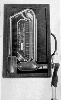
Before evacuating the periscope, the pump
should be checked by attaching a mercury manometer to the suction side. The manometer
reads in millimeters. It does not begin to register until a vacuum of 29 inches is reached. If
the pump is operating properly, it pulls a flat
vacuum, that is, the height of the mercury in
both legs of the manometer becomes equalized.
Care must be taken to keep the pump level to
prevent loss of oil from the exhaust port.
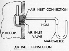
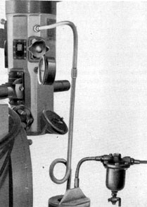
Connections are made for evacuating as illustrated in Figures 2-1 and 2-2. All leads should
be kept as short as possible. A sealing compound
should be used to insure tight joints at the periscope air inlet and outlet valves and at other
connections in the evacuating system. It may
also be necessary to seal over the inlet and outlet air-valve screws. Sealing compound should
not be used on any other part of the instrument.
12
The periscope is then evacuated until a vacuum of preferably 2 mm absolute (and in no case
more than 4 mm) is attained. The time required
to reach this pressure is usually from three to six
hours, depending on the amount of moisture
present. When this pressure has been attained,
the air outlet valve is closed and the pump secured. The vacuum is then held for three hours
as a check on the tightness of the periscope and
the removal of all water vapor. If a slight rise in
pressure occurs, it will be caused by residual
moisture and further pumping will be required.
The periscope is now ready for filling with nitrogen. The nitrogen bottle is connected to the
instrument through a silica-gel dryer and filter,
Figure 2-1. Cross-sectional view of air inlet valve
body.
or cold trap of acetone-CO2 mixture. A small
amount of nitrogen should be bled to the atmosphere before making final connection at the periscope air inlet to remove any water vapor or dust
in the line from the filter. The nitrogen is then
slowly introduced, building the pressure up to 8
pounds. Nitrogen should not be taken from a
bottle in which the pressure has fallen as low as
400 psi.
The Bureau of Ordnance Mark 3 Mod 0 Instrument Dryer, or the Bureau of Ships nitrogen
dryer manufactured by the Navy Yard, Philadelphia, Pa., can be used for drying the nitrogen,
provided they are modified. This equipment utilizes silica-gel. Tests have demonstrated that this
material is satisfactory for periscope work, provided freshly reactivated gel is used for each
servicing. The color test should not be used to
determine the dryness of silica-gel. Reactivating
can be accomplished by heating in a covered kettle or pan to a temperature of 480 degrees to 500 degrees F for
2 hours.
Where silica-gel is used, there is a possibility
of introducing particles of the gel into the periscope and it is not possible to check the drying
procedure by making a dewpoint test. For these
reasons, the method of drying using the acetone-CO2 (dry ice) mixture should be used wherever
dry ice is available.
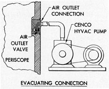
Figure 2-2. Cross-sectional view of air outlet valve
body.
In making connections to the air inlet and air
outlet valves on the periscope, the air-valve connection, supplied with the periscope tool and
spare parts boxes is utilized.
The Bureau of Ships instructs the manufacturer of periscopes and the building yards to
treat each new periscope by a process similar to
that just described before installation in new submarines and to attach an appropriate tag to each
instrument so treated. Under the following circumstances the Bureau requests that the forces
afloat dry and recharge periscopes in service as
just described and attach a tag to show date and
pressure of recharging:
1. When the internal pressure of any periscope
falls to 4 psi or less. If the pressure is found to be
between 4 and 7 1/2 psi, it should be increased to
10 psi with nitrogen dried by a silica-gel dryer or
by the cold trap method and bled down to 7 1/2
psi.
13
2. When a periscope is overhauled or disassembled.
3. When a periscope is reported to be fogging,
if internal fogging is indicated.
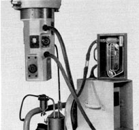
C. INSTRUCTIONS FOR CYCLING
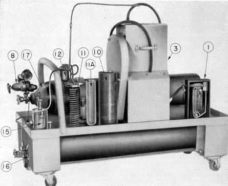
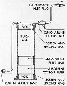
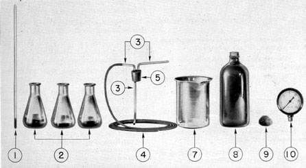
2C1. Cycling equipment. The following equipment is used in cycling (Figure 2-3).
6. Silica-gel dryer (Figure 2-17). (Note: Silica-gel should not be used where CO2 is available.)
7. Silica-gel.
8. Reducing valve for nitrogen flask.
9. Apiezon soft wax.
10. Thermos jar of pyrex, 2 3/4 inches inside
diameter, and 12 inches deep, properly insulated
in a metal container having 1/2-inch cork insulation surrounding the flask, and a wax seal covering the joint between insulation and the flask.
11. Copper coil of 3/8-inch tubing, 15 feet long,
coiled to 2 1/2 inches outside diameter and inserted in the flask.
11a. Wire screen.
12. Cuno air filter attached in the line between the nitrogen tank and the copper coil. (A
filter using a sintered bronze Porex disk may also
be used.)
Figure 2-3. Cycling equipment.
14
13. 0.5 liter of liquid acetone, technical grade.
14. Three pounds of CO2 to fill the flask.
15. Snow Man CO2 machine.
16. CO2 Supply (20 bottles).
17. Nitrogen bottle.
Note: In the cold trap method of drying, items
10, 11, 13, 14, 15, 16, and 17 are required and
items 6 and 7 are not. If silica-gel drying is used,
the reverse is true.
2C2. The Snow Man CO2 machine. The Snow
Man is a small, compact, automatic machine for
producing solid carbon dioxide with a temperature of 114 degrees F below zero. From one 50-pound
bottle of CO2 gas, the machine will make about
ten 12-ounce solid CO2 cakes.
The machine is operated in the following
manner:
1. Lay the bottle of CO2 on its side and raise
the bottom of the tank so that it is about 4 inches
higher than the valve end. Connect one end of
the copper tubing to the drum and the other to
the valve on the side of the Snow Man, using the
fiber washers attached to the machine.
2. Before turning on the gas, be sure that the
cover of the Snow Man is clamped down tight,
and the handle valve is closed. Then open the
valve at the CO2 bottle, and the machine is ready
for operation.
3. Open the handle valve just slightly, until
the gas is heard going into the machine. Hold this
valve open for about 3 minutes or until the safety
valve blows. When the safety valve blows, it indicates that the cavity is filled with dry ice. Close
the handle valve and raise the cover. The cavity
contains a cake of dry ice weighing 12 ounces.
4. Do not open the handle valve wide. Doing
so only wastes gas, and does not form a solid cake
of dry ice.
5. While the machine is in operation and a
cake of dry ice is being formed, do not become
alarmed at the escape of gas from the sides and
bottom of the machine. This is the excess gas that
escapes from the machine during and after the
making of each cake of dry ice.
6. After making each cake, clean the opening
leading to the safety valve.
7. As the volume of gas in the tank decreases,
the time necessary to make additional cakes of
dry ice increases.
2C3. Steps in cycling. Cycling a periscope should
be accomplished as follows:
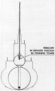
1. If the procedure is carried out on board a
submarine, the periscope is first elevated from
Figure 2-4. Periscope elevated.
the periscope well of the submarine to a height
sufficient to give the repairman access to the air
inlet and outlet connections (Figure 2-4).
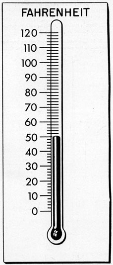
2. In no case should the periscope be cycled
at a temperature less than 50 degrees F as the partial
pressure of the water vapor below this temperature is too low to insure complete drying (Figure
2-5). If the temperature is less than 50 degrees F, the
periscope should be removed from the submarine
and transported to a convenient building where
15
Figure 2-5. Safe cycling temperature.
cycling can be accomplished and where a temperature above 50 degrees is maintained.
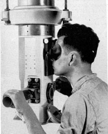
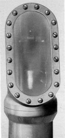
3. Inspect the periscope by observing through
it, checking first for external fogging on the head
and eyepiece window (Figures 2-6, 2-7, 2-8).
Clean lens paper or a selvyt cloth should be
used to wipe off any external fog.
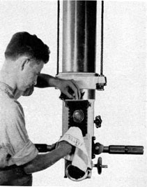
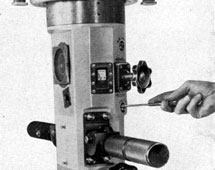
4. Remove the OUTLET PLUG from the
AIR OUTLET connection of the periscope (Figure 2-9).
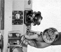
5. On periscopes without a built-in pressure
gage, place a 0 to 25 psi or 0 to 50 psi gage in this
outlet connection (Figure 2-10).
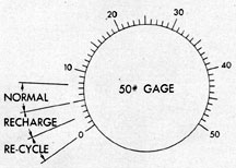
6. Slowly open the AIR OUTLET valve. A
pressure of 5 to 7 1/2 psi is normal, but one
Figure 2-6. Observing through periscope.
between 2 and 5 psi indicates that the periscope
should be recharged at the first opportunity.
Pressure lower than 2 psi denotes a dangerous
condition and may indicate that the periscope is
breathing and hence likely to become fogged internally without warning (Figure 2-11). Continued loss of pressure in the periscope, or the
excessively free movement of any operating
shaft in the eyepiece box, should be cause for an
investigation into the tightness of the packing
glands. When a periscope is cold, the observer's
breath may cause temporary fogging of the outside of the eyepiece window. This condensation
can be removed by opening the rayfilter housing
16
Figure 2-7. External fogging of head window.
and the condition ceases as the instrument becomes warmer.
7. Close the AIR OUTLET valve.
8. Remove the pressure gage from the outlet
connection of the periscope (on periscopes without a built-in pressure gage).
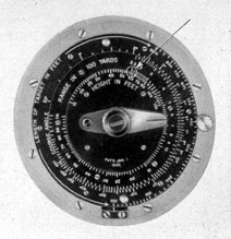
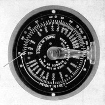
9. To remove the stadimeter housing assembly turn the stadimeter handwheel (12) to the
observing position, as noted by the stamped
numerals located on the stadimeter housing (67
Figure 2-8. Wiping off external fog from eyepiece
window.
and 8, Figures 4-24 and 6-8, respectively). The
number 58 on the height scale dial (52) should
appear approximately opposite the value 2.2 on
the range scale dial (50, Figure 4-24). Opposite
values of 58 and 2.2 are illustrated in Figure
2-12. In periscopes without the course angle, the
number 15 on the height scale dial (13) should
appear approximately opposite the value 220 on
the range scale dial (14, Figure 6-8). This setting
is shown in Figure 2-13. This will make possible
Figure 2-9. Removal of air outlet plug.
17
Figure 2-10. Insertion of 50 psi gage in outlet
connection and opening outlet valve.
the rapid reassembly of the stadimeter housing assembly. Remove the four stadimeter housing bolts
(30, Figure 4-24) and then takeoff the stadimeter
housing assembly with care to avoid bending the
stadimeter transmission shaft (22 and 12, Figures 4-27 and 6-10, respectively). An automatic
stop prevents rotation of the stadimeter handwheel (12, Figure 4-24) when not in place.
10. If the periscope requires recycling, remove
all the external projection fittings on the eyepiece box, such as the stadimeter housing, training handles, focusing knob, and rayfilter attachment. Access to the packing glands is thus given
so that they may be tested for leaks under a 100-psi nitrogen pressure. Testing is preferably done
by immersion in water but an application of
soapy water may be used.
Figure 2-11. Internal nitrogen pressure ranges for
servicing.
Figure 2-12. Infinity setting of stadimeter dials of
Type II periscope.
11. Release the internal gas pressure, if any,
by opening the AIR OUTLET valve.
12. After the internal gas pressure is released,
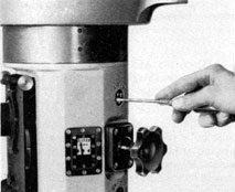
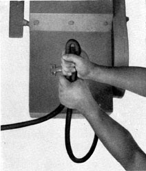
close the AIR OUTLET valve. 13. Remove the INLET PLUG from the AIR
INLET connection (Figure 2-14).
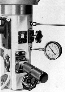
14. Insert the hose fitting in the AIR INLET
connection of the periscope. Steps 14 and 15 are
illustrated in Figure 2-15.
Figure 2-13. Infinity setting of stadimeter dials of
Type III periscope.
18
Figure 2-14. Removal of air inlet plug.
15. Insert a 0 to 150 psi gage in the AIR OUTLET connection.
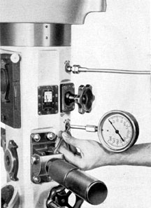
16. Open the AIR OUTLET valve (Figure
2-16).
17. The hose pressure from the reducing valve
of the nitrogen bottle is reduced from high to low
Figure 2-15. Insertion of nitrogen fitting in inlet
connection and pressure gage In outlet connection.
Figure 2-16. Opening the air outlet valve with an
Figure 2-16. Opening the air outlet valve with an offset screwdriver.
Figure 2-17. Silica-gel dryer.
19
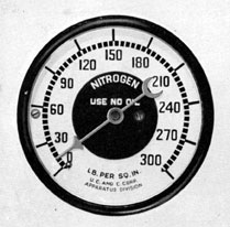
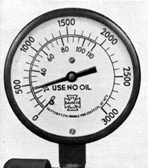
Figure 2-18. Nitrogen gage indicating 10 psi.
pressure so that in filling the periscope a low
charging rate may be used.
18. Attach a silica-gel dryer and filter (Figure
2-17) or the cold trap acetone-CO2 mixture (Figure 2-29) in the line connecting the reduced pressure nitrogen to the AIR INLET connection of
the periscope.
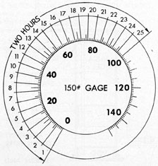
Figure 2-19. Series of 4-pound steps during a 2-hour period.
19. Figure 2-17 shows a metal disk filter inserted in this line to pick up any dirt which may
pass through the silica-gel dryer and filter.
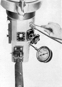
20. Open the AIR INLET valve when the
pressure on the charging line is 10 psi, as shown
by the pressure gage (Figure 2-18).
21. Fill the periscope slowly, taking 2 hours to
build up a pressure of 100 psi in a series of
4-pound steps (Figure 2-19), waiting about 5
minutes between steps. Strong gas currents in the
periscope should be avoided at all times to prevent deposits of dust on the optical surfaces; too
rapid building up of pressure may derange the
optical system.
22. Close the AIR INLET valve when the
pressure reaches 100 psi gage (Figure 2-20).
23. Close off the nitrogen pressure at the nitrogen bottle.
Figure 2-20. Closing air inlet valve.
20
24. Remove the charging line connection from
the AIR INLET connection of the periscope.
25. Check the periscope thoroughly by means
of soapy water (Figures 2-21, 2-22, 2-23, and
2-24), or preferably by immersion in water, and
minutely examine it for leaks, particularly
through the packing glands. All leaks must be
eliminated; otherwise a high vacuum cannot be
obtained. The renewal of packing, tightening of
packing glands, and gaskets around the head and
eyepiece windows must also be checked.
Figure 2-21. Pressure testing outer head and head
window with soapy water.
26. When the tightness of the periscope is insured, the pressure is slowly released over another
2-hour period.
27. Close the AIR INLET valve, and remove the pressure gage from the OUTLET
connection.
28. Open the AIR OUTLET valve of the periscope to release the pressure as described in
Step 26.
Figure 2-22. Pressure testing with soapy water.
Figure 2-23. Pressure testing with soapy water.
21
29. When all gas pressure has been released,
close the AIR OUTLET valve.
30. Connect the mercury manometer fitting to
the AIR INLET connection (Figure 2-25).
31. Connect the evacuating fitting into the
AIR OUTLET connection.
Figure 2-24. Pressure testing with soapy water.
32. Open the AIR OUTLET valve after the
pump has been started, and proceed with evacuation of the periscope. All leads should be short,
and with as few joints as possible, to reduce the
number of possible leaks.
33. Open the AIR INLET valve so that the
line to the mercury manometer gage is free to
record the vacuum as the evacuating procedure
is carried out.
34. The CENCO HYVAC pump must not be
left unattended. If the pump should stop, oil or
oil fumes may be sucked into the periscope and
deposited on the optics, making necessary a
major overhaul of the instrument. If the pump
Figure 2-25. Mercury manometer fitting in air inlet
connection and evacuating fitting in air outlet
connection.
gives indication of stopping, the hose connection
should be promptly kinked (Figure 2-26) and the
AIR OUTLET valve closed.
35. Evacuate the periscope until the mercury
manometer shows a reading of 4 mm or less
(Figure 2-27).
36. When the vacuum has been attained, close
the AIR OUTLET valve and secure the pump.
Figure 2-26. Kinking of evacuating hose.
22
7. Hold the vacuum for 3 hours as a check on
the tightness of the periscope and the removal of
all water vapor. If residual water is present, a
slight rise in pressure will occur and further
pumping will be necessary.
38. Remove the evacuating connection from
the AIR OUTLET connection.
39. Close the AIR INLET valve and remove
the manometer from the AIR INLET connection.
40. The periscope is now ready for filling with
nitrogen. Connect the nitrogen flask, or bottle,
to the instrument through a silica-gel dryer and
filter (Figure 2-17), or cold trap of acetone and
dry ice (Figure 2-29). If the cold trap of acetone
and dry ice is used, bleed off a small amount of
nitrogen to the atmosphere before making final
connection to the periscope AIR INLET connection. This removes any moisture or dust in
Figure 2-27. Mercury manometer reading less than
4 mm.
the line from the filter. (Navy Specified nitrogen
has been tested at New London with the dewpoint testing equipment; readings of -56 degrees C
have been obtained direct from the nitrogen
bottle.)
41. Insert the pressure gage in the AIR OUTLET connection.
42. Open the AIR OUTLET valve to allow
free passage of gas to the pressure gage.
43. Connect the nitrogen hose fitting to the
AIR INLET connection of the periscope.
44. Open the AIR INLET valve slowly, introducing nitrogen, and slowly build up the pressure
to 10 psi.
45. Nitrogen should never be taken from a
bottle in which the pressure has fallen to 400 psi
(Figure 2-28). Moisture would thus be introduced
in the periscope since all nitrogen contains some
moisture.
46. Close the AIR INLET valve.
47. Secure the nitrogen pressure.
48. Disconnect the nitrogen INLET fitting
from the AIR INLET connection,
49. Insert the INLET plug into the AIR INLET connection.
50. If acetone and dry ice are available, the
following method is used for drying nitrogen:
a) Figure 2-29 shows the passage of nitrogen
from the nitrogen bottle through a reducing
valve into a metal disk filter and into the coil of
copper tubing which is immersed in a bath of
acetone and dry ice.
b) The dewpoint of the nitrogen passing
through the bath is lowered to a temperature of
-69 degrees to -74 degrees C. The dewpoint of the nitrogen
may be tested as it passes through the cold trap
into the periscope, providing an outlet for this
test is available.
c) Insert a filter made of metal disks between
the nitrogen bottle and the dryer to prevent introduction of dirt, dust, scale, and lint into the
periscope. A sintered bronze Porex filter may
also be used.
d) In the cold trap, the acetone-CO2 mixture
serves to dry several periscopes if done consecutively. Additional dry ice may be added to keep
23
the temperature down. After several days, however, the acetone becomes polluted and should be
distilled or thrown out, and a fresh mixture used.
51. The dewpoint test should now be made in
accordance with the procedure described in Section 2C5. Upon completion of a satisfactory
dewpoint test of -50 degrees C or lower, the periscope is
bled down very slowly to 7 1/2 psi through the
AIR OUTLET valve. Secure the AIR OUTLET
valve when the pressure on the mechanical pressure gage registers 7 1/2 psi. (With the built-in
pressure gage type, it is only necessary to observe the pressure indicated.)
52. After evacuating and cycling procedure is
completed, the AIR INLET and OUTLET plugs
and external fittings are assembled in inverse
order.
2C4. Dewpoint and testing equipment. Dewpoint
is the temperature at which the water vapor
in any mixture of a gas and water vapor becomes
saturated or condenses. The dewpoint is found
by cooling the mixture at a constant pressure
until saturation occurs.
The dewpoint test equipment, consisting of a
silvered surface on an Erlenmeyer flask in contact with the gas under test, is cooled by immersing the flask in an acetone-CO2 mixture. As
soon as the temperature of the surface of the flask
reaches that of saturation of the gas vapor under
test, a film of the condensed vapor appears. A
thermometer is provided to measure the temperature of the flask surface by measuring the temperature of the acetone-CO2 mixture surrounding
the immersed Erlenmeyer flask. The temperature
at which this clouding appears is the dewpoint.
Figure 2-29. Nitrogen passing through cold trap.
Figure 2-30 shows the equipment necessary to
complete the dewpoint test.
1. One centigrade thermometer, range -100 degrees
to +50 degrees C.
2. Three 200-ml Erlenmeyer pyrex flasks,
with bottom and part of sides silvered,
copper-plated, and coated with acetone resisting enamel, or with the internal area
silvered and lacquered.
3. 12 inches of glass tubing.
4. Four feet of rubber tubing.
5. Rubber stopper for Erlenmeyer flask.
6. 1/2 lb of CO2
24
7. 1000-ml pyrex beaker, large enough to immerse a 200-ml Erlenmeyer flask in 2
inches of acetone-CO2 mixture.
8. 0.5 liter of acetone.
9. Soft apiezon wax for sealing fittings.
10. Pressure gage, range 0 to 30 psi.
2C5. Steps in taking a dewpoint test. A dewpoint,
test should be taken as follows:
1. Heat the Erlenmeyer flasks on a hot plate
to drive out all moisture. This is done before assembly with a rubber stopper.
2. Bleed nitrogen from the AIR OUTLET
connection of the periscope through rubber tubing connected to the glass tubing of the inlet of
the 200-ml flask. Allow an extremely light flow
of nitrogen to escape from the glass exhaust tube
outlet. This light flow can be noted by placing
the outlet tube to a moist lip and feeling the light
exhaust flow of nitrogen.
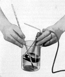
3. Fill the glass beaker with 0.5 liter of liquid
acetone.
4. Immerse the Erlenmeyer flask in the acetone in the glass beaker to about 1 inch above the
silvered sides and take a temperature measurement
with the centigrade thermometer. Watch
carefully for a clouding of the gas vapor, as the
glass tubing is suspended to within 1/4 inch of the
inner glass surface of the bottom of the flask.
5. Add powdered dry ice and continue to take
successive measurements with the thermometer,
stirring the acetone-CO2 mixture.
6. Keep the thermometer raised from the bottom inner surface of the glass beaker (Figure
2-31). A false reading may occur if the thermometer comes in contact with the dry ice.
7. Watch closely for the clouding film on the
inner bottom surface of the 200-ml flask (Figure 2-32); the silvered surface on the bottom of
the flask aids in detecting this film.
8. When the clouded film of condensed gas
vapor is observed, record the temperature. Although a temperature of -50 degrees to -69 degrees C is not
likely to be encountered by a submarine in service,
having the dewpoint in this range provides a
factor of safety and will keep the periscope free
from fogging for a longer period if minute leaks
should occur.
9. A series of three complete tests is necessary. After each dewpoint test, be sure that the
lines and flask are thoroughly dry for each succeeding test.
Figure 2-30. Viewpoint testing equipment.
25
Figure 2-31. Thermometer raised from inner bottom
surface of glass beaker.
10. Three Erlenmeyer flasks are used. This
provides a dry container for each test, without
any loss of time caused by warming and drying.
2C6. Safety precautions for cycling and evacuating periscopes. The following safety precautions
should be observed in using the vacuum drying
system:
1. Be sure that oil is not introduced into the
periscope.
2. Use a reducing valve to lower the pressure
of the gas from the tank or bottle.
3. Use dry silica-gel. It should be dried for 2
hours at 500 degrees F and must be of granular form.
4. Be certain that the filter is clean and tight.
5. Check to ascertain that all connections are
tight.
6. Bleed out all lines before filling the
periscope.
7. Never evacuate a periscope at temperatures less than 50 degrees F.
8. Be sure that the periscope is tight, as all
efforts are useless if the periscope leaks.
9. Keep the vacuum pump in a horizontal
position and watch carefully to see that the pump
Figure 2-32. Clouding film on inner bottom surface
of flask.
does not stop while pulling a vacuum. The pump
must always be attended during the evacuating
of the periscope.
10. Always take the dewpoint test from the
AIR OUTLET connection.
11. Always charge the periscope using a series
of 4-pound steps for approximately 2 hours.
12. Never use a nitrogen bottle which has
dropped to a pressure as low as 400 psi.
13. Dry out the charging cold trap copper coil
after completing every fourth charge.
14. Use apiezon soft vacuum wax around the
hose fittings of the AIR INLET and AIR OUTLET connections to insure a complete seal.
15. Dry the Erlenmeyer flasks before each
dewpoint test.
2C7. Cleanliness. The greatest care must be
taken to avoid introducing dust, dirt, or moisture
into the periscope. All apparatus must be kept
clean and used for no other purpose. The cold
trap and vacuum lines should be blown out before each use with a strong jet from the dry
nitrogen flask. Hose lines should be as short as
possible and the joints hermetically tight. If periscopes are dried or recharged in place on the vessel, all equipment should be available on board.
Long lines for dry gas or vacuum should not be
used under any circumstances.
26
D. CARE OF FLOODED PERISCOPE
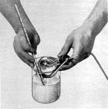
2D1. Preservation of flooded periscopes. 1. A
drain opening is provided in the base of the eyepiece box on the Type II and III periscopes.
Opening this drain first requires the removal of
the stadimeter housing assembly. A screw with a
lead washer is secured in this tapped hole. Removal of this screw permits the repairman to
drain the periscope.
2. When periscopes have been flooded and
subsequently emptied of water, the resulting
corrosion damages certain parts beyond repair unless prompt counter-measures are taken.
3. As soon as possible after flooding, flush with
fresh water and dry thoroughly, if practicable.
Then apply a rust preventive compound similar
to Tectyl Grade III or No. 511 to internal parts.
4. If Tectyl is not available, the periscope
should be sealed after flushing and left filled with
fresh water until repairs are effected.
E. REMOVING AND INSTALLING A PERISCOPE
2E1. Removing a periscope. A periscope is removed as follows:
1. The precautions to be taken when elevating a periscope are:
a) Notify any men working around the vicinity to stand clear.
b) If a cover plate is provided remove the
cover plate from the top steady bearing of the
submarine.
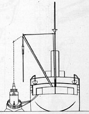
2. The submarine is moored on either the
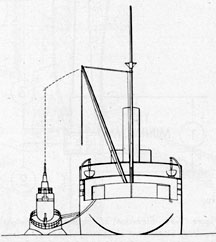
starboard or port side of the tender (Figure 2-33).
Generally it is moored on the side where the periscope is transported most easily to the optical
shop.
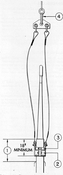
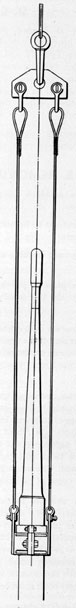
3. Elevate the periscope to the height required, which should be high enough to accommodate two slings of sufficient length to clear the
fragile head (Figure 2-34). Each sling is provided
with a spreader bar to prevent contact with the
relatively fragile head and taper section of a
Type II periscope. The same procedure is followed for other types of periscopes.
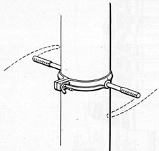
4. Secure a suitable forged steel hoisting
clamp (2, Figure 2-34) of ample proportion
around the outer tube at least 12 inches below
the joint between the outer tube and the taper
section (Figure 2-24). The hoisting clamp should
be lined with asbestos brake lining, or emery
cloth placed with the smooth side to the outer
tube. Special steel bolts must be used.
5. One or 2 safety clamps (3a Figure 2-34)
(the brass clamps supplied with the shipping box
will serve) should be secured above the hoisting
clamp. Under no circumstances are poorly fitting
clamps or clamps containing setscrews to be used,
nor should any clamp be directly over the joint
between the body tube and the taper section,
as severe damage to the periscope may result
(Figure 2-34).
6. Place the hook of the lifting crane (4,
Figure 2-34) in the hook opening of the spreader
bar.
7. Raise the periscope to the observing position and transfer the weight of the periscope to
the lifting crane (Figure 2-35). This gives the repairman access to all external parts.
Figure 2-33. Submarine moored on port side of
tender.
27
Figure 2-34. Elevation of periscope to height
required; attachment of hoisting clamp and safety
clamp; placement of the hook of the lifting crane
in the spreader bar.
Figure 2-35. Raising the periscope to the observing
position.
28
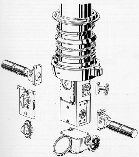
8. Remove all external parts which project
beyond the circumference of the outer tube
Figure 2-36). At the time of removal, note the
position of the reference marks on the square
ends of the training handle packing gland assembly shafts with corresponding reference
marks on the training handles for proper reassembly.
Note the reference marks on the focusing knob assembly in a similar manner.
a) Remove the training handles by taking out
eight hinge, bracket bolts (19 and 21, Figures
4-43 and 4-44, respectively), for the left and
right training handles of a Type II periscope.
Figure 2-36. Removal of external parts of periscope.
29
b) Remove the focusing knob assembly by
taking out four lockscrews (10, Figure 4-39).
c) Remove the rayfilter by pulling, outward on
both spring-actuated plunger knobs (24, Figure
4-40).
d) To remove the stadimeter housing assembly, follow the same procedure stated in Step
9, Section 2B8.
e) Remove the eyepiece attachments that are
secured to the anchor screw pins (19, Figure
4-29) projecting from the eyepiece box itself.
Figure 2-37. Rotation of periscope to detect
binding.
f) Remove the hoisting yoke when the crane
has taken the full weight of the periscope as follows (Figure 7-26):
1) Remove the wire rope with the sleeves for
the 7/16-inch wire rope (11) and with the adjusting nuts for the wire rope (10). Lash down the
slack wire rope to the wire rope drum of the
submarine.
2) Take out the cover ring lockscrews (4).
3) Unscrew the cover ring (2) with a spanner
wrench. Remove the hoisting yoke body (1),
phosphor-bronze locating collar (9), lower ball bearing race (8), ball bearings and retainer (7),
and the upper ball-bearing race (6).
4) Remove the split ring (3). All parts of the
thrust bearing should be protected from dirt or
grit.
5) Remove the cover ring (2).
9. Slack off the hull stuffing box gland of the
submarine before removing the periscope.
10. The periscope must be guided vertically
while being hoisted by the crane. Station one
man on the fairwater to spot the crane boom
directly over the periscope to prevent binding in
the steady bearings. Attach a suitable hinged
clamp with handles over the outer tube, to rotate
the periscope back and forth to observe any
tendency toward binding (Figure 2-37). If binding occurs because of the rolling of the tender
or the submarine, the hoisting operation should
be stopped at once, and resumed only when this
condition has been corrected.
11. Hoist the periscope clear of the submarine,
and transport it to the upper deck vertically
(Figure 2-38). Lower the periscope in the open
Figure 2-38. Hoisting the periscope clear of the
submarine to the upper deck of the tender.
clamp cap and clearance wall of the hinge carriage to within 4 inches of the deck. Line the
clamp cap and clamp section of the hinge carriage
with emery cloth placed with its smooth side
against the outer tube. Secure the clamp cap and
30
clamp section of the hinge carriage to the outer
tube with two special bolts and nuts over the
emery cloth. Insert the toggle bolt in the lined-up holes of the supporting arm and clearance wall
periphery projection after the clamp cap is secured (Figure 2-39).
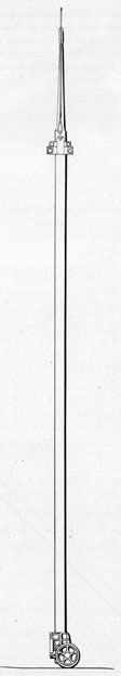
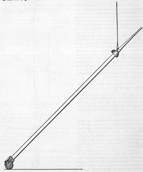
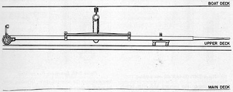
12. Carry the lower end of the periscope and the
hinge carriage toward the position in which it will
lie, in the horizontal position (Figure 2-40), lowering the upper end of the crane. The large wheels of
the hinge carriage roll the lower end of the periscope toward its proper horizontal position as the
upper end is lowly lowered (Figure 2-41).
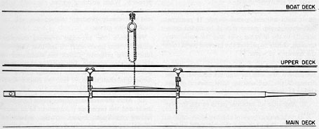
13. When the periscope is near the horizontal
position, locate the clamp carriage in the proper
position, with the upper half of the clamp hinge
of the clamp carriage open. Lower the periscope
to the lower half of the clamp carriage and close
the upper clamp half, securing it with a swinging
wing nut (Figure 2-42). The hinge carriage has
clearance around the eyepiece box, and is secured
to the outer tube just above the coupling, thus
carrying the weight of the periscope as it is
swung to the horizontal position, and preventing
damage to the eyepiece box.
14. Remove the hoisting clamp and the safety
clamps (Figure, 2-34).
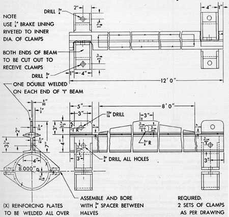
15. Assemble two horizontal lifting clamps to
the periscope outer tube (Figure 2-43) between
the, clamp carriage and the hinge carriage. Two
3/4-inch steel bolts, not shown in Figure 2-43,
are used on each clamp to fasten the two halves
of the clamp together.
16. Roll the periscope by means of the wheels
on the clamp carriage and the hinge carriage to
the inboard transfer opening of the upper deck
(Figure 2-44). Secure the horizontal lifting
spreader bar to the plate extension of both horizontal lifting clamps with special bolts 3/4 inch
in diameter. (These bolts are not shown in
Figure 2-43.)
17. Place the hook of the chain fall of the
overhead track in the hook opening in the horizontal lifting spreader bar, and carry the weight
of the periscope by the chain hoist (Figure 2-45).
Remove the hinge carriage and open the upper
half of the clamp carriage.
Figure 2-39. Attachment of hinge carriage.
31
18. Transport the periscope, lowering it to
the overhead chain hoists of the main deck.
Transfer the load of the periscope to the chain
hoists of the main deck, attaching each hook in
the shackle at each end of the horizontal lifting
spreader bar (Figure 2-46).
19. Roll the periscope into the optical shop
and lower it onto the separated channel optical
benches.
20. Remove the horizontal lifting spreader
bar and the horizontal lifting clamps.
Figure 2-40. Periscope and hinge carriage at 45 degrees position.
32
Figure 2-41. Hinge carriage at horizontal position.
Figure 2-42. Upper part of periscope in clamp
carriage.
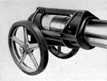
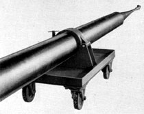
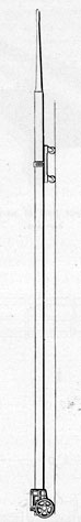
Figure 2-43. Details of horizontal lifting clamps and lifting spreader bar.
33
Figure 2-44. Transfer of periscope on hinge and
clamp carriages to the inboard transfer opening in
the upper deck.
2E2. Installing the periscope. The periscope is
installed as follows:
1. Remove the Garlock chevron packing or
the emergency flax packing gland assemblies
(Figures 2-47 and 2-48) by removing the packing gland nuts.
2. Transport the periscope from the optical
shop of the ship to the submarine, following
Steps 3 to 20 of Section 2C1 in the inverse order.
3. To effect smoother guidance, apply grease
freely to the periscope as it enters the steady
bearings of the submarine.
4. Replace the suitable hinged clamp with
handles (Figure 2-37) over the outer tube, and
rotate the periscope back and forth as it is
lowered to observe any tendency toward binding.
Follow precautions to prevent binding stated in
Step 10 of Section 2C1.
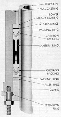
5. Hull stuffing box packing. The hull
stuffing box gland provides a water seal joint
between the hull casting and the outer tube of
the periscope. It may be made up of two types of
packing: Garlock chevron packing or emergency
flax packing assemblies.
a) Figure 2-47 shows the details of the Garlock chevron packing assembly, which consists
of the following: upper metal packing ring, one
ring of Garlock chevron packing, lantern ring,
two rings of Garlock chevron packing, lower
metal packing ring, filler ring, and a metal
packing gland.
1) Assemble the Garlock chevron packing assembly loosely to determine a measurement from
the face of the upper metal packing ring to the
inner shoulder face of the metal packing land.
Measure the distance from the lower face of the
lower steady bearing to the lower face of the
extension ring. The difference in the measurements should indicate a 1/16 to 3/32-inch clearance
(looseness) between the lower face of the steady
bearing and the upper face of the upper metal
packing ring after the metal packing gland is
brought up hard against its shoulder. To establish the 1/6 to 1/32-inch clearance may require
replacing the filler ring, or cutting it down to
obtain the desired clearance.
2) Assemble the Garlock chevron packing
gland assembly as shown in Figure 2-47. After
the metal packing gland is brought up hard
against its shoulder, check the clearance around
the inner circumference of the packing gland and
the outer tube with a .006-inch feeler gage.
3) In view of the temperature zones likely to
be met by the submarine, the grease used to pack
the lantern ring will vary. For example, in warm
climates a heavy grease is required for sealing
the lantern ring.
34
4) It is of prime importance that the angle of
75 degrees not be exceeded at the lower end of the lantern ring; this also applies to the lower end of the
upper metal packing ring.
5) It is believed that in cases where leakage
occurs with Garlock chevron packing, it can be
attributed to a slight off-center condition existing
between the periscope and the hull gland, which
results in forcing the Garlock packing out of
round and opening the seal between the periscope
and the packing. Experience has shown that in
most cases leakage can be eliminated by the
addition of one or two rings of Garlock chevron
packing, without any appreciable increase in
effort required to train the periscope. Where
additional rings of Garlock packing fail to stop
leakage, flax packing as shown in Figure 2-48
will stop leakage, but some increase in effort will
be necessary to train the periscope.
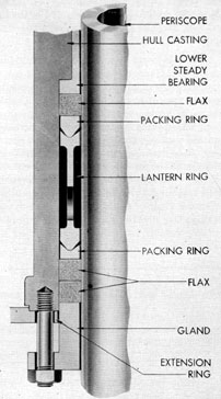
b) Figure 2-48 shows the details of the emergency flax packing assembly which consists of
removing the Garlock chevron packing rings
and the filler ring, and installing three flax packing rings. One ring of 5-inch flax packing is
placed above the upper metal packing ring, and
two rings of 5/8-inch flax packing below the lower
metal packing ring. Cut each flax packing ring
with square ends, and measure it to conform with
the inner circumference of the hull casting, not
the outer diameter of the periscope.
In taking up the packing gland, use a feeler
gage around the periscope to insure equal clearance and proper tightening of the packing gland.
This is essential as the shoulder of the packing
gland is not brought up against the extension
ring.
6. Assemble the azimuth circle and auxiliary
circle attachment to the extension ring. Train
Figure 2-45. Overhead chain hoist hook placed in hook opening in the horizontal spreader bar.
Figure 2-46. The periscope is transferred to the overhead chain hoists of the main deck.
35
Figure 2-47. Garlock chevron packing.
the periscope to the forward and after bench
marks and check the azimuth circle to read correctly on the lubber's line.
7. After the assembly of the hoisting yoke,
fill it with mineral grease Grade II medium.
Soft-water pump grease should be added occasionally to the hoisting yoke and the stadimeter
housing, chiefly to protect the internal parts from
the entrance of water.
8. Raise and lower the periscope while filling the lantern ring area through the external grease
fitting of the hull casting with mineral grease
Grade II medium.
9. Assemble all external parts in the inverse
order.
10. Train the periscope through 360 degrees several
times to observe the condition of the steady
Figure 2-48. Emergency flax packing.
bearings and the azimuth circle. Grinding may
be noted if chips are left inside the steady bearings, and the azimuth circle is not located
properly. When grinding occurs, the outer tube
must be smoothed down to remove scratches,
and the steady bearings cleaned out and repacked with grease.
11. Check the periscope training handles,
altiscope, and power shift to see that they are
functioning properly. Check the stadimeter in
the observing position, to note that there is no
double image at the infinity reading. Check the
focusing mechanism to see that the diopter readings are -3 and +1 1/2.
12. After the necessary observations have been
made and the periscope is known to be in satisfactory condition, report to the submarine
officer, requesting that he inspect the periscope
for approval.