6A1. Purpose of calibrating log. Each complete log system is calibrated at the factory
with a standard U-tube mercury manometer,
having a scale graduated in knots. This scale
is based on a constant determined by towing-tank experiments on a standard rodmeter.
The rodmeter used with each log system has
physical dimensions identical with that used
in towing-tank experiments. Thus it is possible to calibrate each log system by means
of the standard manometer mentioned above.
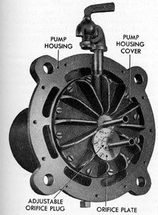
The pump unit contains an orifice plug as
shown in Figure 6-1, the position of which
determines the calibration of the log. During
factory tests this orifice plug is rotated to a
position that will cause the log to indicate a
speed equal to that indicated by the standard
mercury manometer. The centerline on the
orifice plug is then extended to the orifice
plate and marked as reference point O. While
Figure 6-1. Pump orifice plate.
maintaining the mercury deflection at a steady
value, the orifice plug is rotated to either
side of O for the purpose of making calibration lines at 2, 4, and 6 percent, plus and
minus. The equipment is shipped from the
factory with the pump setting at 0 percent.
When the equipment is installed in a ship, a
factory representative checks the operation of
the entire system and set the pump orifice at
a value that was determined during the measured mile trials of a ship of the same class.
When the correction for a particular type or
class of ship is unknown, the setting is left
at 0 percent. No changes in speed calibration
settings should be made on the shaft rpm knot data alone. The data upon which the
rpm-knot table, or curve, are based were in
most cases determined during the measured
mile trials of the ship, or on another ship of
the same class. Trial conditions can rarely,
be duplicated; and even with suitable corrections for foul bottom, variations in displacement and trim, and effect of wind and
sea, speed indications thus derived are worthless for calibrating the log system. Similarly,
checking distance indications by comparison
of log readings with distances traveled between ports cannot be used for recalibration
purposes since the current effect cannot be
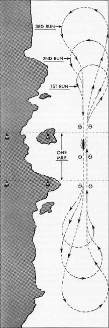
determined with the degree of accuracy required. Thus the most accurate and suitable
method of checking the calibration of a log
under actual operating conditions is to run
the ship over a measured course 1 mile in
length (Figure 6-2).
6A2. Preparations for checking log. If the
ship is not near a standard measured mile
course, it is possible to use fixed points one
mile apart as shown in Figure 6-2. If possible,
a location should be chosen in which the current effect is small and having a direction
parallel to the axis of the ship's course. The
depth of water should be at least 20 fathoms.
Shallower water will prevent the ship from
101
Figure 6-2. Measured mile course.
developing proper speed for a given propeller
shaft rpm, and the log will tend to read high
when checked in shallow water because of
wave systems established by the ship. Before
making the runs over the measured mile, the
log system should be checked for proper operation as follows:
The hydraulic system should be entirely
free of air. The system should be vented as
described in Section 3A3. All hose connections must be tight. Leakage at the drip fitting on the pump must not exceed three drops
per minute. If leakage is in excess of this
amount, the pump must be disassembled and
the rotary seal inspected and replaced if required. The 3Y circuit of the master speed
indicator must receive controlled 60-cycle a.c.
from the constant frequency supply. A frequency greater than 60 cycles will result in a
proportional negative error in speed reading.
A frequency less than 60 cycles will result in a
proportional positive error in speed reading.
For example, if the frequency is 59 cycles
instead of 60 cycles, the speed indication will
be 1 division high in 60, or 1.66 percent high
at all indications. This would amount to a
0.25 knot over-reading at 15 knots, and a 0.4
knot over-reading at 25 knots. If the frequency is 61 cycles, the speed indication will be
1.66 percent low at all indications. As the log
distance is not affected by the 3Y frequency
variations, this speed error may be detected
by aiming, with a reliable stop watch the registering of 1 mile on the master speed indicator distance counter while the ship is maintaining a steady speed. (This particular test
need not be made on a measured mile course.)
Readings should be taken of the log speed indicator during this test. The average speed
calculated from the stop watch reading should
check with the average of the pointer reading
within 1 percent.
6A3. Operation and calculation. The ship
should make three runs at each speed selected.
One run should be made in each direction over
the measured course, and then the first run
should be repeated. As many speeds should
be selected as time will permit. In general,
three typical speeds - low, medium, and high -
are the minimum for proper log calibration.
A signal system should be used to permit observers to read and record simultaneous readings
102
at the propeller shaft revolution indicators, and the master speed indicator. The crew
members stationed at the propeller shaft revolution indicators will read and record indications on each revolution counter at the
beginning and end of each run. They should
also read and record indications on the rpm
pointer every 15 seconds throughout the run.
compensate for this error. Let us assume
that the log averages 1.0 percent high at all
speeds. Adjust the orifice plug by loosening
the six screws in the orifice plate, and rotating the orifice plug clockwise, to subtract a
value of 1.0 from the original setting. In the
example given, the orifice plug would be
moved from 0 percent to a point halfway
Calibration of Pitometer Underwater Lag on a Measured Mile
U.S.S................ Displacement: 1300 tons Condition of Bottom: Clean (1 month out of dock) Setting of Pump Orifice: 0% Projection of Rodmeter: 36 inches Relation of Underwater Sound Projector to Rodmeter: Rodmeter 3 ft. to Stbd. of Stbd. Sound Ball
Date: April 14, 1941 Place: Provincetown, Mass. Length of Course: 1 mile Depth of Water: 20 fathoms Wind Direction: 180 degrees (T) Wind Intensity: 5 knots Direction of Sea: 180 degrees (T) State of Sea: 1
Record and Average Data as follows:
Run No.
Ship's Course
Elapsed Time Min. Sec.
Knots Over Ground
Log Knots
Log Distance
Average rpm
1
311
3:54.0
15.39
15.20
1.01
200.0
2
131
4:06.0
14.63
15.17
.99
201.0
3
311
3:52.7
15.47
15.19
1.01
200.5
Average = Average of Run No. 1, No. 2, No. 3 and No. 2
Average:
15.03 Knots over ground
15.18 Log knots
1.00 Log distance
200.5 Average rpm
Crew members stationed at the master speed
indicator should read and record the indications of the distance counter at the beginning
and end of each run. They should read and
record the speed pointer every 15 seconds
throughout the run. The data shown above
should be summarized and entered in the machinery history.
If, after measured course trials are held, the
recorded data positively indicate that the log
has a definite error, the orifice plug in the
pump unit (Figure 6-1) may be adjusted to
between 0 and (-) 2.0 percent. This would be
a setting of (-) 1.0 percent. Tighten the orifice plate screws securely. The orifice plug
is not to be adjusted each time the log appears to be in error. Once a setting has been
properly made there should be no further occasion for changing it unless some structural
alteration is made in the ship's hull forward
of or near the rodmeter. A structural change
may affect the pressures at the rodmeter,
thus necessitating a new correction.