5A1. General. Extreme vigilance and care
should be practiced in the inspection, cleaning, and repair of parts. Personnel performing repair work should use common sense in
judging whether or not a part should be put
back into service or discarded. If there is any
doubt regarding this, replace the part. With
the exception of bearings and electrical equipment, corrosion should be removed from parts
by washing them in clean fresh water. Dry
the parts thoroughly, and apply a light film of
gyro oil to prevent rusting or corrosion. Use
Navy-approved cleaning fluid to clean grease
and oil from the parts. Keep bearings oiled
and clean by wrapping them in wax paper, or
cloth, until needed for assembly. The area in
which the repair work is being performed
should be kept in an absolutely clean condition in order to prevent any dust and dirt
from getting on the parts.
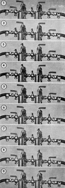
5A2. Operating the system on a static head.
This operation is a means of checking the
operation of the log system and other equipment connected to the log system while the
ship is at rest on the surface. By shutting
off the pressure on one side of the bellows,
unequal pressure is obtained on the bellows,
and the system will operate at one speed in
the same manner as if the ship were underway.
This permits the checking and inspection of
the system under operating conditions. Operate on the static head as follows: Turn the
valves from the secured position as shown in
Figure 3-2 to the static head operating position as shown in Figure 3-7. The system will
now operate at approximately 5 knots. After
inspection, turn the valves to their secured
position as shown in Figure 3-2. The pump
motor should then stop turning and the speed
pointers should beat zero.
B. MAINTENANCE OF RODMETER
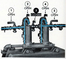
5B1. Testing for obstruction in the rodmeter.
The rodmeter may become clogged with jellyfish, mud, seaweed, or other foreign matter.
Consequently the pressure difference will not
be normal, and the mechanism will not register correctly. The following test must be
performed when the ship is on the surface:
Position the vent cocks and valves as shown
in Figure 5-1. If a full stream of water does
not flow from both vent cocks, it is an indication that the particular line not flowing is
clogged.
5B2. Blowing out the rodmeter. This operation should be performed with the rodmeter
in its extended, or operating, position. It is
good practice to blow out both lines even if
the tests for obstruction indicate that only
one line is clogged, as foreign matter has undoubtedly entered both passages. Blow out
the rodmeter in the following manner: Disconnect the hose from the static pressure
valve nipple on the control unit. Pinch the
end of the hose to prevent leakage of water.
If the line is completely clogged, water will
not leak from the hose. Connect the low-pressure air line of the ship to the static hose, and
blow the obstruction out of the hose and rodmeter into the water outside of the ship. Do
not apply the low-pressure air hose to the
lines that enter the control unit, as air pressure will damage the sensitive mechanism.
When a full stream of water is obtained from
the static hose, install the end of the hose
over the nipple on the static pressure valve
and install the hose clamp to secure the hose
in position. Blow out the dynamic line in the
same manner.
5B3. Removing solid obstructions from the
rodmeter. If obstructions are not removed by
blowing out the rodmeter with compressed
air, the following operations will be necessary:
Raise the rodmeter to its fully housed
position (Figure 5-2). Close the sea valve.
Unlatch the stop bracket at the top of the
hoist assembly by opening and removing the
lock which secures the bracket in position
above the rodmeter, and swing it to one side
out of the way (Figure 5-2). Remove the
lower end of the rodmeter from the sea valve
extension by raising the rodmeter to the
upper sprockets. Using a soft brass wire, dig
out the obstructions from the orifices (openings) at the lower end of the rodmeter.
Do not use steel wire or a drill to clean
the orifices as they may score the orifices or
break off in the openings.
Blow out the rodmeter as described in
Section 5B2 with the exception that the rodmeter need not be extended into the sea.
Have one crew member hold his hand near the
orifices to detect the flow of air which indicates that the orifice and tubing are clear.
Repeat the operation until all passages are
clear. Align the lower end of the rodmeter
with the opening in the sea valve extension
and lower the rodmeter to its fully housed
position (Figure 5-2).
At this point the tip of the rodmeter is
approximately 1 inch above the sea valve gate.
Open the sea valve. Swing the stop bracket
to its normal position above the rodmeter and
secure in place with the lock. It is important
that the stop bracket be in position above the
rodmeter at all times except during the above
operation, or when the rodmeter is being replaced. Lower the rodmeter to its normal
housed position or to its fully extended position as desired. Place the hoist crank in the
brackets provided, and replace the deck plate
over the sea valve.
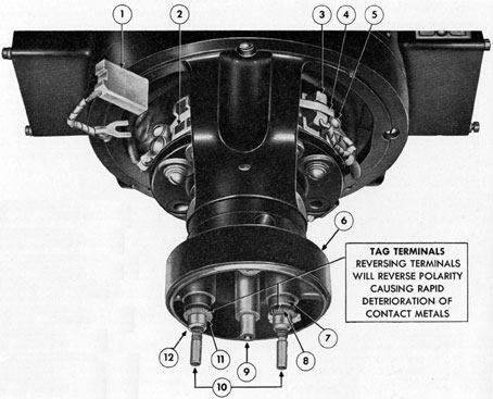
C. REPLACING DAMAGED RODMETER
5C1. General instructions. If the rodmeter
is bent so that it cannot be drawn up into the
ship, it will be necessary to install a spare
rodmeter. Do not attempt to force the damaged rodmeter up into the ship, as the hoist
mechanism may be damaged. The removal
and installation operations should be carried
out only when the ship is surfaced. If the
damaged rodmeter is to be salvaged, it may be
accomplished if a diver is available. Lower
the diver over the side of the ship so that
he can rig a line around the damaged rodmeter. Secure the other end of the line to
the ship so that the rodmeter may be pulled
out of the water after it is pushed out of the
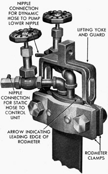
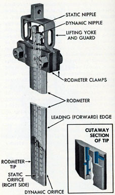
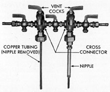
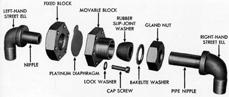
sea valve. The rodometers of all submarines
are equipped with two valve assemblies
mounted on the upper end openings of the
rodmeter (see Figure 5-3), instead of the conventional nipple installation as shown in
Figure 5-4. This necessitates a different procedure for removing and installing the clamp
and guard assembly. These two procedures
will be covered in the following operations.
5C2. Breaking out the spare rodmeter. Break
out the spare rodmeter and place it alongside
of the hoist mechanism so that it will be immediately available when needed.
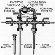
5C3. Rumoring the clamp and guard assembly (nipple installation). (See Figure 5-4.)
Loosen the hose clamps and remove the two
lengths of hose from the nipples on the upper
end of the rodmeter. Unscrew the longest
nipple (after nipple) and plug the hole in the
rodmeter with a wooden plug. Remove the
33
Figure 5-2. Rodmeter in secured position.
forward nipple in the same manner. Remove
the two nuts and bolts that secure the clamps,
and guard to the rodmeter and remove the
clamp and guard assembly. Raise the guard,
by means of the hoist, up against the stop
bracket above the rodmeter (Figure 5-2).
Figure 5-3. Rodmeter with valves installed.
5C4. Removing the clamp and guard assembly (valve installation). Loosen the two hose
clamps (one on each hose) that secure the
ends of the hose to the nipples provided on
the valve assemblies at the upper end of the
rodmeter (Figure 5-3). Remove the hose and
clamps. Remove the two bronze nuts and bolts
that secure the two clamps and the guard to
the top of the rodmeter, and remove the
clamps. Raise the guard and yoke assembly
up against the stop bracket by means of the
hoist provided for raising the rodmeter.
34
It may be necessary to remove one or both
valve handles from the valve stems in order
to get enough clearance to raise the guard.
This is accomplished by removing the two
nuts (one on each handle) that secure the
valve handles to the valve stems, and by removing
the handles. Make a rough sketch of
the position of the valve assemblies so that
they can be installed in their original position
on assembly. Spread the two valve assemblies
apart so that one of them can be unscrewed
without interference from the other valve
assembly. Unscrew and remove the lower
valve assembly from the elbow which connects
this valve assembly with the opening in the
top of the rodmeter. Plug the elbow opening
with a wooden plug. Unscrew the complete
valve assembly from the other opening on
top of the rodmeter, and plug this opening
in the rodmeter with a wooden plug. Unscrew
and remove the elbow of the lower valve assembly from the top of the rodmeter, and
plug the opening in the top of the rodmeter
with a wooden plug.
5C5. Installing the valve assemblies in the
top of the rodmeter. (See Figure 5-3.) The
spare rodmeter is equipped with nipples and a
clamp and guard assembly. For those ships
which have valve assemblies installed instead
of the conventional rodmeter nipples, the following procedure is necessary to install the
valve assemblies in the spare rodmeter:
1. Remove the clamp and guard assembly
from the spare rodmeter by removing the two
bronze nuts and two bolts that secure the
clamps and guard in position at the upper end
of the rodmeter, and remove the clamps and
guard.
2. Unscrew and remove the two nipples
from the top of the rodmeter.
3. Apply a coating of white lead compound to the threads of the valve assemblies
to be installed.
4. Install the elbow of the lower valve
assembly (previously removed from the damaged rodmeter) in the after (static) opening
in the top of the rodmeter. Refer to the
sketch previously made at disassembly, and
tighten this elbow to its original position.
5. Install the valve assembly in this elbow, tightening the valve until secure. Be
sure that the valve stem is facing upward.
6. Disassemble the second valve assembly
by unscrewing the horizontal nipple and valve
assembly from the elbow and nipple assembly.
Also remove the valve bottom and stem assembly from the valve body. This disassembly
is necessary in order to obtain the proper
clearances while installing the second valve
assembly in the rodmeter.
7. Install the elbow and nipple in the
forward (dynamic) opening on top of the
rodmeter. Tighten until the elbow is in its
original position. Refer to the sketch made
previously for the position of the elbow.
8. Install the valve body and nipple into
the elbow.
9. Install the valve bottom and stem assembly into the valve body, making certain
that the valve stem is facing upward.
5C6. Installing the clamp and guard assembly. (See Figure 5-4.) The two clamps and
the guard are stamped at their ends. These
numbers should be adjacent to one another
when these pieces are assembled on the rodmeter. Place the two clamps around the upper
end of the spare rodmeter in such a manner
that the clamps are over the knock-out pins
provided at the top of the rodmeter. Place
the guard between the clamps. Align the
mounting holes in the three pieces, and install
the two bronze bolts and nuts that secure the
clamp and guard assembly to the rodmeter.
Tighten the nuts securely.
5C7. Installing the spare rodmeter. (See
Figure 5-4.) The following procedure should
be used in installing the rodmeter:
1. If the damaged rodmeter is partially
raised, push it downward until the knock-out
pin rests on top of the packing gland in the
sea valve extension. It may be necessary to
use a heavy hammer and wooden block to start
the rodmeter downward.
2. Place the tip of the spare rodmeter on
top of the damaged rodmeter, being sure that
the dynamic orifice in its leading edge is facing forward. Note the arrows stamped on the
35
rodmeter for facing the rodmeter in the
proper direction.
3. Remove the cotter pin and the clevis
pin which secure the old guard to the lifting
bar on the hoist chain, and remove the old
guard. Align the opening in the lifting bar
with the opening provided in the guard on the
spare rodmeter, and install the clevis pin and
cotter pin which secure the lifting bar to the
guard assembly.
4. Place the loose end of the dynamic
hose over the nipple provided on the dynamic
fitting on top of the rodmeter. The opposite
end of this hose is attached to the pump.
Secure the hose to the nipple by tightening
the hose clamp on the end of the hose. Place
the end of the static hose on the nipple provided on the fitting on top of the rodmeter.
The opposite end of the static hose is attached
to the control unit. Secure the hose to the
nipple by tightening the hose clamp on the
end of the hose.
5. Remove the knock-out pin from the
damaged rodmeter. Push downward on the
spare rodmeter to drive the damaged rodmeter
downward and out of the ship.
6. Vent the system in accordance with
the instructions in Section 3A3.
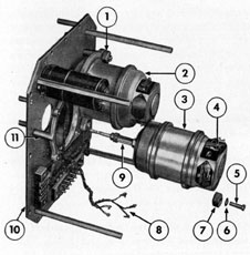
Figure 5-4. Cutaway view of Pitometer rodmeter.
D. MAINTENANCE OF PUMP
5D1. General. The pump is removed, disassembled, inspected, cleaned, repaired, adjusted, and lubricated whenever the leakage
from the pump exceeds three drops per
minute; or whenever the pump becomes noisy
due to worn bearings or because the impeller
blades are hitting on the cover.
5D2. Period of overhaul. If possible, the
pump assembly should be removed, disassembled, cleaned, inspected, lubricated, adjusted,
and/or repaired, if necessary, every 45 days.
If the tactical situation does not warrant
servicing the pump at 45-day intervals, it
should be overhauled after every patrol to
keep the pump operating correctly. A shorter
or longer interval of overhaul is left to the
discretion of the commanding officer.
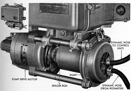
5D3. Removing the pump. (See Figure 5-5.)
Have the rodmeter in its secured position
with the sea valve closed. Disconnect the two
lengths of hose from the pump by loosening
the two hose clamps (one on each hose) that
secure the hose to the nipples on the pump,
and remove the hose and clamps. Remove
the four nuts that secure the pump to the
spacer (mounting) rods, and remove the pump
assembly from the spacer rods.
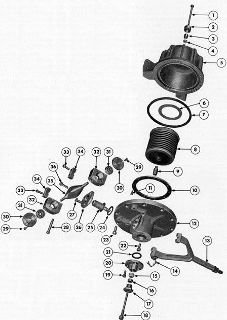
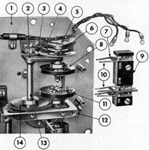
5D4. Disassembly of the pump assembly.
(See Figure 5-7.) Following is the procedure
for disassembling the pump assembly.
36
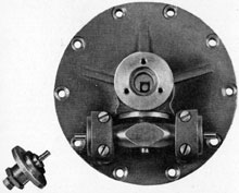
Figure 5-5. Pump installed.
1. Remove the 11 screws that secure the
pump cover jacket to the pump housing, and
remove the cover jacket. Do not remove the
marked orifice plate.
2. Remove the 12 screws that secure the
housing cover to the housing, and remove the
housing cover. Lift the rubber gasket off
the housing. Turn the pump assembly over
so that the impeller blades are facing downward, and rest the pump assembly on
the cover jacket with the impeller blades in
the opening in the cover jacket. Do not
rest the impeller blades on an uneven surface
as they will be damaged.
3. Remove the four screws that secure
the housing jacket to the pump housing, and
remove the housing jacket.
4. Loosen the two setscrews (one on each
piece) that secure the coupling and the fan
on the impeller shaft, and remove the coupling and fan.
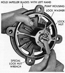
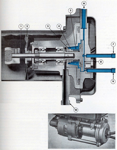
Figure 5-6. Removing impeller shaft lock nut.
37
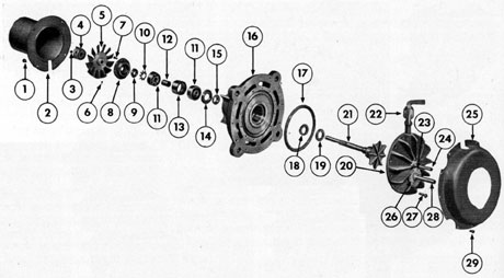
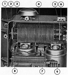
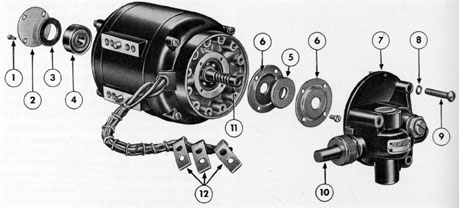
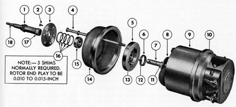
1. HOUSING JACKET SCREW
2. PUMP HOUSING JACKET
3. COUPLING SET SCREW
4. PUMP COUPLING
5. PUMP FAN
6. FAN SETSCREW
7. END CAP SCREW
8. END CAP
9. LOCK NUT
10. LOCK WASHER
11. BALL BEARING
12. BEARING INNER RACE SPACER
13. BEARING OUTER RACE SPACER
14. SHIELD WASHER
15. THROWER DISK
16. PUMP HOUSING
17. GASKET
18. ROTARY SEAL INSERT
19. SEAL RING
20. PUMP HOUSING COVER
21. PUMP IMPELLER, ASSEMBLY
22. VENT COCK
23. ORIFICE PLATE SCREW
24. HOSE CONNECTING NIPPLE TO CONTROL UNIT
25. PUMP COVER JACKET
26. ORIFICE PLATE
27. HOUSING COVER SCREW
28. HOSE CONNECTING NIPPLE TO RODMETER (DYNAMIC)
29. COVER JACKET SCREW
Figure 5-7. Pump disassembled.
5. Remove the four screws that secure
the end cap to the pump housing, and remove
the pump end cap.
6. Bend down the lug of the external
toothed lock washer that secures the lock nut
in position. Using the special lock nut wrench
(Figure 5-6), remove the lock nut from the
end of the impeller shaft. Do not place the
impeller blades in a vise. Lift off the lock
washer. Pull the impeller assembly out of the
pump housing.
7. Insert a brass or fiber rod V inch in
diameter into the pump housing from the impeller end of the pump housing and push out
the two ball bearings, two spacers, thrower
disk, and shield washer from the pump housing. Do not use a steel rod as the parts will
become burred, and the bearings will not align
properly at assembly.
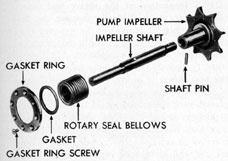
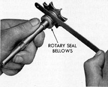
5D5. Disassembly of the impeller assembly.
(See Figure 5-8.) The impeller assembly is
disassembled as follows:
1. The rotary seal bellows is disassembled from the impeller assembly when visual
inspection reveals the fade of the bellows to
be grooved, burred, or badly corroded.
2. Remove the eight screws that secure
the impeller gasket ring to the impeller, and
remove the gasket ring. Remove the gasket
from the ring or from the impeller if the gasket is sticking to the impeller. Carefully pull
the rotary seal bellows from the impeller and
off the impeller shaft.
3. Place the impeller shaft in a soft-jawed vise in such a manner that the pin that
secures the shaft to the impeller is parallel to
the jaws of the vise. Using a pin punch, drive
out the pin from the impeller and the, impeller
38
Figure 5-8. Impeller disassembled.
shaft. The impeller shaft is disassembled
from the impeller only if a gap between the
shaft and the impeller indicates that the pin
that secures the shaft to the impeller has been
distorted, or sheared off due to the application
of too much pressure on the lock nut which
secures the bearings and spacers to the impeller at a previous assembly operation.
5D6. Inspection and repair of impeller shaft.
(See Figure 5-8.) Inspect the impeller shaft
for straightness. Inspect the shaft for security of mounting in the impeller. The impeller
shaft should be securely mounted in the impeller, and the pin that secures the shaft to
the impeller should be in place. A gap between the impeller shaft and the impeller is
Figure 5-9. Checking length of rotary seal bellows
an indication that the pin that secures the
shaft to the impeller has been distorted, or
sheared off at a previous assembly. If the
shaft is not straight, or the pin has been distorted or sheared off, remove the pin from the
shaft and impeller. Press a new shaft into
the impeller, and install a new, 3/32-inch
monel pin which secures the shaft to the impeller. A bronze pin may be substituted for
the monel pin if the latter is not available,
but do not use steel or stainless steel pins as
they will corrode and fail prematurely. If the
threads are damaged, touch them up on a
lathe. The diameter of the screws is 0.391
inch (10 mm), 32 threads per inch.
5D7. Inspection of the impeller blades. (See
Figure 5-8.) Inspect the impeller blades for
straightness and depth. The blades should
be straight. The depth of the impeller blades
on a new, impeller is 0.189 inch. If the impeller
blades are worn more than 0.002 inch below
the depth of the blades of a new impeller,
that is, the depth of blades is less than 0.187
inch, the impeller should be replaced, or the
calibration of the system will be incorrect.
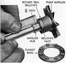
5D8. Inspection of the rotary seal bellows.
(See Figure 5-8.) Visually inspect the face
of the rotary seal bellows. If worn, pitted; or
corroded, replace the bellows and gasket. Use
KR monel bellows for replacement, if available. Use monel or bronze screws on the
gasket ring. Do not use stainless steel screws
on the gasket ring as the steel screws corrode
badly when used with monel. Check the
Figure 5-10. Stretching rotary seal bellows.
39
Figure 5-11. Refacing rotary seal insert.
dimension from the impeller hub to the bellows
face (Figure 5-9). This dimension is very
critical and should be exactly 13/32-inch. If
the bellows is too short (dimension more than
13/32-inch), the pump may leak excessively.
If the bellows is too long (dimension less than
13/32-inch), the seal faces will wear rapidly,
and may make the pump too tight. This latter
fault will cause the pump to bind at low
speeds.
5D9. Adjusting-the rotary seal bellows. (See
Figure 5-10.) If the bellows are found to be
too short, as described in Section 5D8, they
may be stretched as follows: Place a thin
strip of metal, such as the smooth edge of a
hacksaw blade, between the folds of the
rotary seal bellows. Turn the bellows around
so that the metal blade will stretch the bellows
uniformly. After each turn, measure the distance between the impeller hub to the bellows
face. Repeat the spreading operation until
the dimension between the impeller hub and
bellows face is exactly 13/32-inch. When the
bellows is too long, as described in Section
5D8, compress the bellows by hand (while installed on impeller shaft) until the dimension
between the impeller hub and the bellows face
is exactly 13/32-inch. When the rotary seal
bellows is at proper dimension, the bellows
face must move freely inward and outward
along the shaft.
5D10. Inspection of the rotary seal insert.
(See Figure 5-7.) Visually inspect the seal
insert for pitting, corrosion, or grooves indicating wear. If pitted or badly corroded, the
seal insert should be replaced. If lightly
worn (grooved) the seal may be refaced. If
the seal insert is bronze, and a monel insert
is available, the bronze insert should be replaced with the monel insert. If a monel replacement is not available, the bronze insert
may also be refaced. However, the bronze
insert will continue to corrode even though
refaced and should be replaced by a monel
insert at the first opportunity.
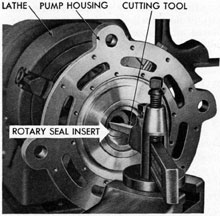
5D11. Refacing the old seal insert. (See
Figure 5-11.) Place the pump housing in a
lathe. Align the housing up to 0.0005 inch,
using a dial indicator on the monel liner face.
Take light cuts across the seal insert face
until score marks are removed. Undercut the
inner face at the inside diameter of the insert
0.010 inch below the face of the seal insert.
Occasionally when an old seal insert is refaced, enough metal is removed so that the
Figure 5-12. Pressing out rotary seal insert.
40
pump will leak when installed, due to a looseness between the insert, micarta ring, and the
bellows. This may be remedied by disassembling the pump and stretching the bellows to
take up the space between the bellows and the
seal insert.
Figure 5-13. Installing rotary seal insert.
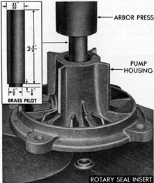
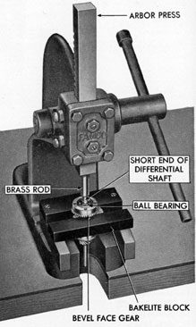
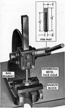
5D12. Replacing the seal insert. (See Figures 5-12 and 5-13.) Place the pump housing
on the bed of an arbor press with the large end
of the housing downward. Using a special
rod as shown in Figure 5-12, press out the seal
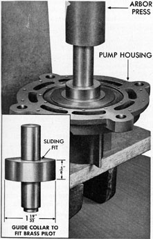
insert. To install a new seal insert, place the
housing on the bed of an arbor press with the
small end of the housing downward. Put a
moderate amount of pipe compound on the
outer surface of the shoulder of the insert
and on the inner surface of the opening
through the housing liner. Place the new seal
insert in the housing with the shouldered end
of the seal downward. Using a special seal
installing tool as shown in Figure 5-13, press
the seal insert into housing.
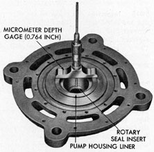
5D13. Refacing the new seal insert. (See
Figure 5-11.) At manufacture, the dimensions
of the seal insert are such that it may be faced
to allow for removal of burrs or score marks
from the seal surface after the pressing operation. This precaution is also taken to allow
Figure 5-14. Checking rotary seal insert.
for facing the seal in the event it is not pressed
true in the housing. Reface a new seal insert
as follows: Place the pump housing in a lathe.
Align the housing up to 0.0005 inch, using a
dial indicator on the monel liner face. Take
light cuts across the seal insert face until the
proper dimension of 0.764 inch is reached and
the face of the seal insert is smooth. This
dimension is the distance from the monel liner
face of the housing to the face of the seal
insert, and is determined with a depth gage
as shown in Figure 5-14.
5D14. Inspection of the seal ring. (See Figure 5-7.) Visually inspect the seal ring. The
ring must be perfectly flat, or it should be
0.0005 inch thicker at its outer edge. If it is
worn on either side, the ring should be replaced. The seal ring should always be
41
replaced if the rotary seal bellows or the seal
insert surfaces have been changed. Some pump
assemblies are still equipped with the carbon
ring. Replace the carbon ring with a micarta
ring. In emergencies when micarta seal rings
are not available, a ring turned from lignum
vitae would be satisfactory. Cut across the
grain of the wood to the approximate size;
soak in water for a day, and while it is moist,
turn it to the exact thickness and flatness.
This ring must be kept wet thereafter or it
will warp out of shape, making it worthless.
5D15. Inspection and repair of the thrower
disk and shield washer. (See Figure 5-7.) The
thrower disk and shield washer need not be
replaced unless they are badly worn or bent.
Using a straightedge, inspect the pieces for
flatness. Visually inspect the thrower disk
and shield washer for burrs. Remove nicks
from the inner surfaces of the thrower disk
and shield washer with a bearing scraper.
Remove score marks from surfaces with a finecut file.
5D16. Cleaning and inspection of the bearings. (See Figure 5-7.) Thoroughly clean
the bearings with Navy-approved cleaning
fluid. Dry the bearings thoroughly. In cases
where the grease has become hardened within
the bearing, the bearing should be allowed to
soak in the cleaning fluid until the grease has
softened, and then swished back and forth in
the cleaning fluid until all grease and dirt are
removed from the bearing. Visually inspect
the bearings for pitting resulting from corrosion, and if they are pitted, replace the bearings. The bearings should be smooth and
operate freely. Turn the bearing by hand, and
note any clicking noise which indicates a
cracked ball, or a piece of metal or dirt within
the bearing. If the bearing is thoroughly
clean, and clicking or binding exists when the
bearing is rotated by hand, the bearing should
be replaced: If the bearing is worn so that
there is excessive side play, or excessive end
play between races, it should be replaced.
After cleaning and inspection, oil the bearings
with light oil, and pack the bearings with
grease, Navy, Symbol 14L3. Wrap the bearings in waxed paper until they are to be
assembled.
5D17. Cleaning and inspection of the bearing
spacers. (See Figure 5-7.) Thoroughly clean
and dry the two bearing spacers. Examine
them for pitting, cracks, or scored end surfaces. Spacers with ends that are not smooth
should be replaced. Measure the length of the
spacers. The inner bearing spacer should be
from 0.029 to 0.033 inch longer than the outer
spacer in order that the bearings seat properly
when assembled on the impeller shaft. The
outer spacer should be 0.625 inch long.
5D18. Assembling the shaft and impeller.
(See Figure 5-8.) Place the impeller shaft in
the impeller hub. Align the hole in the shaft
and the hole in the impeller hub, and install
the pin that secures the shaft to the impeller
hub. Be sure that the ends of the pin are flush
with the impeller hub, and that the surfaces
at the ends of the pin are smooth.
5D19. Installing the rotary seal bellows. (See
Figure 5-8.) Place the rotary seal bellows on
the impeller shaft with the recessed end of
the bellows toward the impeller. Install the
rubber gasket over the seal bellows and up
against the impeller (not inside the bellows).
Place the gasket ring over the bellows. Align
the mounting holes in the gasket ring and the
holes in the impeller, and install the eight
screws which secure the gasket ring to the
impeller. Check the dimensions of the rotary
seal bellows as described in Section 5D8.
5D20. Installing the impeller assembly. (See
Figures 5-7 and 5-15) Place the seal ring
(micarta ring if available) over the impeller
shaft and up against the face of the rotary
seal bellows. Place the pump housing over the
impeller shaft with the large end of the pump
housing toward the impeller. Place the
thrower disk on the impeller shaft with the
large flat surface of the ring toward the impeller. Install the shield washer on the impeller shaft with the flat surface of the washer
facing away from the impeller. Install the
inner ball bearing on the impeller shaft with
the shield end of the bearing toward the impeller. Place the inner and outer bearing
spacers on the shaft so that they are adjacent
to the inner ball bearing just installed. Fill
the bearing spacers one-half full with grease,
Navy Symbol 14L3.
42
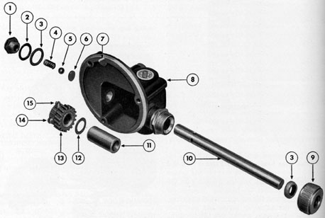
1. IMPELLER SHAFT
2. PUMP FAN
3. ROTARY SEAL INSERT
4. SEAL RING
5. ROTARY SEAL BELLOWS
6. VENTING COCK
7. HOSE CONNECTING NIPPLE, TO CONTROL UNIT
8. PUMP IMPELLER
9. HOSE CONNECTING NIPPLE, TO RODMETER
10. DRIP FITTING
Figure 5-15. Cutaway view of rotary pump.
43
Do not fill the spacers more than one-half
full with grease.
Install the outer bearing on the impeller
shaft with the shield end of the bearing facing
away from the impeller. Carefully press the
ball bearing on the impeller shaft by hand
until the bearing is aligned with, and adjacent
to, the inner and outer bearing- spacers previously installed. Place the toothed lock
washer on the impeller shaft with the teeth
facing upward (away from the impeller).
Place the lock nut on the impeller shaft with
the chamfered end of the nut toward the impeller. Using the special lock nut wrench
(Figure 5-6), and holding the impeller blades
with one hand, tighten the lock nut reasonably
tight.
Do not force-tighten this nut, or the pin
that secures the impeller shaft to the impeller
hub will be sheared off.
Align one of the slots in the lock nut with
one of the teeth in the lock washer, and bend
the tooth upward to secure the lock nut in
position.
5D21. Installing the end cap. (See Figure
5-7.) Place the end cap over the end of the
impeller shaft and up against the small end
of the pump housing. Align the mounting
Figure 5-16. Checking impeller clearance.
holes, and install the four screws that secure
the end cap to the pump housing. There
should be a gap of approximately 0.002 inch or
more between the housing and the end cap.
This end cap clamps the outer race of the
outer ball bearing and therefore holds the entire ball bearing and impeller assembly in
proper position. Do not file off or cutoff the
end cap to eliminate this gap.
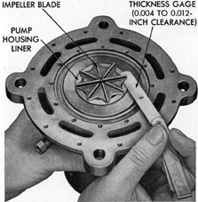
5D22. Checking the impeller blade clearance.
(See Figure 5-16.) Using a thickness gage,
check the clearance between the housing end
of the impeller blades, and the monel liner of
the pump housing as shown in Figure 5-16.
5D23. Installing the fan and coupling. (See
Figure 5-7.) Place the fan on the impeller
shaft with the hub of the fan toward the impeller. Align the setscrew in the fan hub
with the flat side of the impeller shaft, and
tighten the setscrew to secure the fan on the
shaft. Place the half-coupling on the end of
the impeller shaft with the lugs of the coupling facing away from the impeller. Carefully
align the end of the coupling with the end
of the impeller shaft and tighten the setscrew
that secures the coupling to the impeller shaft.
The face of the coupling must be flush with
the end of the impeller shaft.
5D24. Installing the housing jacket. (See
Figure 5-7.) Place the housing jacket in position over the pump housing, and install the
four screws that secure the housing jacket to
the pump housing.
5D25. Installing the pump cover. (See Figure 5-7.) Place the rubber cover gasket in
the groove provided in the impeller end of the
pump housing. Place the finned pump cover
in position on the impeller end of the pump
housing. Align the cover so that the vent cock
is directly opposite the drip fitting on the
pump housing. Install the 12 screws that secure the cover to the pump housing. The
vent cock should be repaired at this time.
Inspect and clean the vent cock as follows:
Remove the nut or cotter pin that secures the
spring and valve assembly in the vent cock
body. Lift the valve assembly from the vent
cock body. Clean corrosion from all parts of
the vent cock, and lubricate with a small
amount of waterproof grease.
44
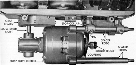
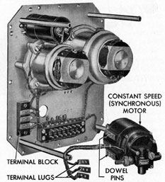
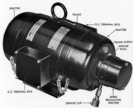
Figure 5-17. Pump drive motor installed.
5D26. Installing the cover jacket. (See Figure 5-7.) Place the cover jacket in position
on the pump housing, and secure it with the
brass or bronze screws provided.
5D27. Installing the pump. (See Figure
5-5.) Before installing the pump, test it under
pressures up to 200 pounds per square inch at
a speed as low as 1 knot in accordance with
the instructions given in Chapter 7. Slide the
pump assembly on the spacer rods, making
certain that the went cock on the pump is
facing upward. Be sure that the coupling on
the pump drive motor shaft is flush with the
end of the drive shaft. Place the rubber block
in one half of the pump coupling. Move the
pump to the left until the two halves of the
coupling are properly engaged; then install
the four nuts that secure the pump assembly
on the spacer rods. Install the dynamic hose
from the control unit on the upper nipple on
the pump, and tighten the hose clamp to secure the hose to the nipple. Install the dynamic hose from the rodmeter on the lower
pump nipple, and tighten the hose clamp to
secure the hose on the nipple. Vent the system
in accordance with the instructions given in
Section 3A3.
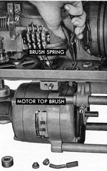
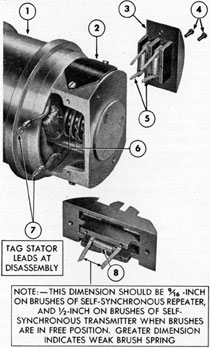
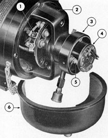
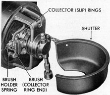
Figure 5-18. Removing upper brush.
45
E. MAINTENANCE OF PUMP DRIVE MOTOR
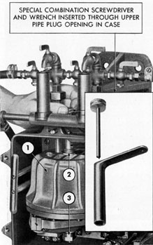
5E1. Removing the brushes. See Figures
5-17 and 5-18.) Remove the 10 screws that
secure the cover on the rotary distance transmitter case and remove the cover. This is
necessary in order to make the upper brush
accessible. Remove the pipe plug from the
bottom of the rotary distance transmitter case.
Unscrew and remove the two caps (one on
each side of the motor) that secure the brushes
in position in the motor. Carefully lift the
two brushes out of the motor.
5E2. Inspection and repair of the brushes.
Visually inspect the brushes. They should
show a polished surface on the end that contacts the commutator. The brushes should not
be less than 3/8-inch long from the contact end
to the shoulder where the brush spring is
attached. Brushes showing wear nearing the
3/8-inch dimension should be replaced. If the
brush contact surface is pitted, smooth off the
surface, using fine sandpaper wrapped around
a cylindrical object. The brushes can be
rubbed across the surface without affecting
the curvature of the face.
5E3. Installing the brushes. (See Figures
5-17 and 5-18.) Place the lower brush in the
hole provided in the lower side of the motor.
Compress the brush tension spring by hand,
and install the cap which secures the lower
brush in the motor. Install the upper brush
in the hole provided in the top of the motor in
the same manner. Install the pipe plug in the
hole in the bottom of the rotary distance transmitter case. Install the case cover.
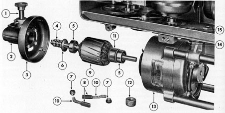
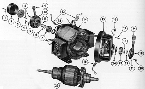
5E4. Removing the armature. (See Figures
5-17 and 5-19.) Remove the pump (see Section
5D3.) Remove the brushes (see Section 5E1).
Remove the two screws that secure the gear
guard to the rotary transmitter case and remove the gear guard. Loosen the socket head
setscrew that secures the drive motor coupling
on the motor shaft, and remove the coupling
and rubber spacer. Remove the four screws
that secure the back end shield on the motor
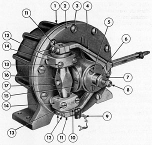
9. ARMATURE CORE AND SHAFT
10. BRUSH SPRINGS
11. COMMUTATOR
12. PIPE PLUG
13. MOTOR FRAME
14. TOP BRUSH HOLDER
15. PIPE PLUG HOLE
Figure 5-19. Pump drive motor partially disassembled.
46
field ring, and remove the back end shield and
armature assembly :from the pump motor. The
armature assembly can then be carefully
pulled out of the back end shield for inspection of bearings.
5E5. Inspection of the bearings. (See Figure
5-19.) Visually inspect the two bearings on the
armature shaft for evidence of pitting due to
corrosion. Turn the bearings by hand. They
should turn easily and freely. A clicking
noise indicates that one or more of the balls is
cracked, and the bearing must be replaced.
A damaged bearing is removed by using a
bearing puller. Press the replacement bearing
onto the shaft in place of the damaged bearing.
5E6. Assembly of the armature. (See Figures 5-17 and 5-19.) Align the worm, spacers,
and bearing on the end of the armature shaft
with the opening in the back end shield, and
carefully push the armature assembly into
the back end shield. Place the armature inside
the motor, being careful when inserting the
shaft through the opening in the front end
shield. Align the mounting holes in the back
end shield with the holes in the field ring, and
install the four screws that secure the back
end shield to the field ring of the motor.
Turn the pump drive shaft by hand to be sure
that the armature and gears are turning freely.
Install the gear guard. Install the two brushes
(see Section 5E3). Install the coupling on the
armature shaft and secure with the setscrew
provided. Install the rubber spacer. Install
the pump (see Section 5D27).
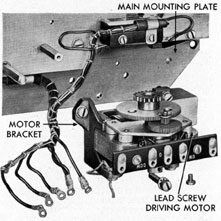
5E7. Removing the pump drive motor as a
unit. See Figure 2-8.) Disconnect the hose
and remove the pump (see Section 5D3). Disconnect the armature and field wires from the
terminal block on the bottom of the rotary
distance transmitter case by removing the
four screws from the terminal block and carefully lifting off the wire terminals with the
blade of a screwdriver. Remove the gear
guard. Loosen the two stop screws that secure
the spacer rod in the motor mounting bracket,
and pull the pump drive motor assembly to
the left and off the rotary, distance transmitter
case.
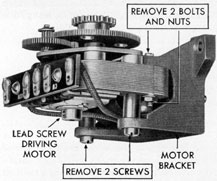
5E8. Installing the pump drive motor. (See
Figures 5-17 and 2-8.) Align the two upper
spacer rods with the motor mounting bracket,
and slide the motor assembly to the right as
far as the stop on the spacer rod will allow.
Make sure that the gears at the left end of the
motor are properly meshed and that the spacer
rod is against the motor mounting bracket.
There should be a slight amount of backlash
between the two external gears. If the gears
do not mesh properly when the stop is against
the motor mounting bracket, it will be necessary to relocate the stop. This is accomplished as follows: Drill out the pin that
secures the stop on the spacer rod. Slide the
motor assembly to the right until the gears at
the left end of the motor are properly meshed.
Slide the stop over against the motor mounting bracket and locate the pinhole. Drill a
hole through the spacer rod. Install a new pin
through the stop and the spacer rod. Install
the gear guard. Connect the two armature
and the two field wires to the terminal block
on the counter mounting plate inside the
rotary distance transmitter case. The terminal block and terminals on the wires are
marked for the location of wires. The corresponding terminals are marked as follows
A+, A-, F+, and F-. Install the pump
(see Section 5D27).
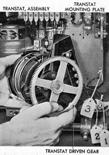
F. TRANSTAT ASSEMBLY
5F1. Removing the transtat assembly. (See
Figure 5-20.) The transtat assembly is removed as a unit as follows: Remove the four
screws and toothed lock washers that secure
the transtat mounting base to the plate back
of the rotary distance transmitter. Carefully
lift the defective unit from the plate, and turn
the assembly to make the wire connections
more accessible. Remove the nuts and flat
washers that secure the wire terminals to the
posts on the transtat assembly. Mark the
wires for ready identification at assembly.
Loosen the setscrew that secures the gear on
the right side of the transtat assembly and
47
remove the gear. Place the gear on the new or
rebuilt transtat assembly to be installed and
Figure 5-20. Removing transtat.
tighten the setscrew to secure the gear on the
shaft.
5F2. Installing the transtat assembly. (See
Figure 5-20.) Place the new transtat assembly
with its assembled gear in position in
front of the rotary distance transmitter in
such a manner that the wires can be connected.
Place the three wires, previously marked, on
their corresponding marked posts, and secure
each terminal with a flat washer and nut.
Place the transtat assembly in position on the
mounting plate provided on the back of the
rotary distance transmitter case, making certain that the gears are meshed, and install the
four screws and toothed lock washers that
secure the transtat assembly in the case. Rotate the transtat gearing by hand over its
entire range and note the position of the
center brush of the transtat at the instant the
upper and lower limit switches are operated.
The brush must still be on the transtat winding. Do not force the gearing beyond the
point where the switches are actuated. If the
brush is not on the winding at each position,
loosen the three clamp screws passing through
the core; shift the core radially to the proper
position, and tighten the screws. Recheck for
proper operation.
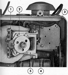
G. MAINTENANCE OF FOLLOW-UP MOTOR
5G1. Testing the follow-up motor. (See Figure 5-21.) Test the operation of the follow-up
motor in the following manner: Remove the
cover from the rotary distance transmitter
case. Disconnect the wire lead from the center
terminal on the motor terminal block. This
terminal is marked C. Move the transtat
brush arm well away from its limit switch.
Using a screwdriver, alternately short-circuit
the terminals marked CW and CCW with the
center terminal. The motor will run first
clockwise and then counterclockwise if it is
operating properly. If the motor is binding,
or inoperative, replace it.
5G2. Removing the follow-up motor. (See
Figure 5-21.) Disconnect the wires from the
terminal block on the motor. Tag the wires
for ready identification. Remove the three
screws and the toothed lock washers that secure the motor assembly to the mounting
plate, and remove the motor.
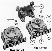
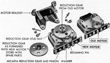
5G3. Exchanging the pinion and spur gear
assembly. The replacement of the spur gear
on the follow-up motor follows exactly the
same procedure as that described in Section
5M5 for the gear replacement of the lead
screw drive motor.
5G4. Installing the follow-up motor. (See
Figure 5-21.) Place the follow-up motor assembly in position on the mounting plate.
Install the three screws and toothed lock
washers that secure the motor to the mounting
plate. Connect the wires to the terminal block
on the motor. Tighten the terminal screws.
Install the cover on the case.
48
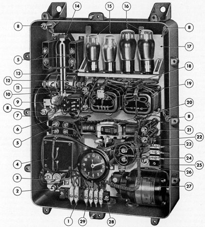
H. REMOVAL AND INSTALLATION OF ARMATURE RECTIFIERS
5H1. Removing the armature rectifiers.
(See Figure 5-22.) Burned-out rectifiers are
detected by the presence of deposits of molten
metal on the bottom of the rectifier disks.
This metal has the appearance of melted
solder. Remove the rectifiers in the following
manner: Remove the case cover. Unsolder
the lead wires to each armature rectifier and
tag each wire to make certain that it is installed in the same position on the new rectifiers. Remove the four screws and toothed
lock washers that secure the rectifier brackets
to the mounting plate and remove both rectifiers as a unit.
5H2. Replacing the rectifier stacks in the
rectifier assembly. (See Figure 5-22.) Remove
the four nuts (two at each end) that secure
the brackets to the rectifier studs, and remove
the brackets. Save any spacer washers that
may be installed on the rectifier studs for replacement on the new rectifiers. Place the
spacer washers, if used on the old rectifier
1. TERMINAL BLOCK
2. FOLLOW-UP MOTOR
3. TRANSTAT MOUNTING PLATE
4. TRANSTAT, ASSEMBLY
5. MOTOR BRACKET
Figure 5-21. Removing follow-up motor.
assembly, on the studs of the new rectifiers
in the same position as previously installed.
This is important in order that the same
space between the mounting brackets will be
maintained.
Place the two rectifiers in the mounting
brackets in the same position as the previously
removed rectifiers, making certain that the
name plates are facing in the same direction,
and install the four lock washers and nuts
(two at each end) that secure the brackets to
the rectifier studs. If the replacement rectifiers have square plates (slightly higher current capacity) be sure that the bakelite spacer,
furnished with this type, is properly installed
between the two stacks. The spacer prevents
the stacks from touching if they should become loose during operation. The angle
brackets provided are held between the inside
face of the mounting brackets and the adjacent nuts. Two spacer washers may be
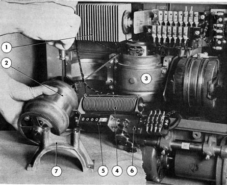
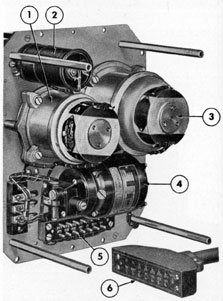
1. ARMATURE RECTIFIER
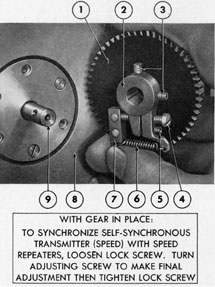
2. SELF-SYNCHRONOUS TRANSMITTER (60 REVOLUTIONS PER MILE)
3. SELF-SYNCHRONOUS TRANSMITTER (360 REVOLUTIONS PER MILE)
4. FIELD RECTIFIER
5. DISTANCE COUNTER
6. COUNTER MOUNTNG PLATE WITH MOTOR TERMINAL BLOCK
7. MOUNTING STRAP Figure 5-23. Removing self-synchronous transmitter.
50
removed to compensate for the thickness of the
two angle brackets.
Be sure to hold the lock nut adjacent to
the inside of the bracket while tightening the
outer nut to prevent the distortion of the
plates.
5H3. Installing the armature rectifier. (See
Figure 5-22.) Place the rectifier assembly in
position on the mounting plate and secure
with the four screws and toothed lock washer
provided. Connect the wires to the terminals
with solder.
I. REMOVAL AND INSTALLATION OF FIELD RECTIFIER
5I1. Removing the field rectifier. (See Figure 5-22.) Evidence of a burned-out field rectifier is the presence of deposits of molten metal
on the bottom of the plates. Remove the field
rectifier as follows: Unsolder the lead wires
from the rectifier terminals. Tag the wires
for location. Remove the four screws and
toothed lock washers that secure the rectifier
assembly to the counter mounting plate, and
remove the rectifier.
5I2. Installing the field rectifier. (See Figure 5-22.) The new rectifier and brackets are
replaced as a unit. Place the rectifier assembly
in position on the counter mounting plate.
Install the four screws and toothed lock
washers that secure the rectifier assembly to
the counter mounting plate. Connect the lead
wires to the rectifier terminals with solder.
J. REMOVAL AND INSTALLATION OF SELF-SYNCHRONOUS
TRANSMITTER
5J1. Removing the distance transmitter.
(See Figure 5-23.) Remove the cover from the
case. Remove the two screws and toothed lock
washers that secure the counter mounting
plate to the transmitter mounting strap, and
swing the counter assembly to one side out
of the way. Remove the four screws and
toothed lock washers that secure the transmitter mounting strap to the mounting cradle,
and remove the strap. Pull the motor out of
the cradle as far as the wires will allow, and
disconnect the two wires from one of the
brush blocks, and three wires from the opposite brush base. Tag the wires for identification. Lift the transmitter from the case. The
other transmitter is removed in the same
manner.
5J2. Installing the distance transmitter. (See
Figure 5-23.) Place the transmitter on the
forward edge of the case so that the wires may
be connected. Connect the three wires to the
terminals in the rear brush block. Connect the
two wires to the front brush base. Place the
transmitter in position in the cradle with
the gear on the shaft properly meshed
with the slow speed gear train in the case.
Place the mounting strap in position and install the four screws and toothed lock washers
that secure the strap to the cradle. Place the
counter mounting plate with the counter in
position on the transmitter mounting strap,
making certain that the dowel holes in the
plates are properly aligned with the dowel
pins on the strap. Install the two screws and
toothed lock washers that secure counter
mounting plate to the transmitter mounting
strap. The other transmitter is installed in
the same manner. Install the case cover.
K. MAINTENANCE OF CONTROL UNIT
5K1. Checking and cleaning the contact
points. (See Figure 2-7.) Remove the cover
from the control unit case and place the top
of the cover on the lower dowel pin of the
case in such a manner that the dowel pin hole
in the top edge of the cover is engaged in the
bottom dowel pin in the case. Secure in this
position with one screw. This causes the unit
to hang level in the gimbal bracket. It is apparent that the control unit contact points
are not properly adjusted if the pump motor
does not stop running when the rodmeter is
secured, and the bypass valve on the control
unit is open.
51
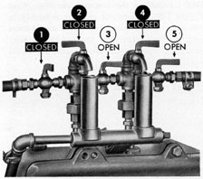
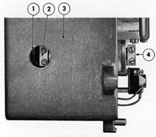
1. DYNAMIC PRESSURE VALVE
2. VENT COCK
3. BYPASS VALVE
4. VENT COCK
5. STATIC PRESSURE VALVE Figure 5-24. Valves in position for adjusting
contacts.
Clean the contact points in the following
manner: Insert a piece of ordinary note paper
between the contact points. Manually press
the contact arm against the paper and adjacent contact point, and drag the paper across
the points. This will usually remove any film
of oil or dirt which may be present on the
points. If this does not stop arcing between
the points, clean the contact points with fine
crocus paper or with a jeweler's file. Operate
the system on the static head to determine
whether this procedure has remedied the
trouble.
5K2. Checking the position of the contact
arm. (See Figure 5-25.) Remove the cover
from the control unit case and hang it on the
lower dowel pin. Place the valves in position
for adjusting the contacts (Figure 5-24.) This
places the static pressure only on both sides
of the bellows, insuring that it is in the neutral, or center, position. Unless otherwise
specified, all adjustments on the control unit
are made with the valves in this position.
Adjustments can be made while the ship is
underway on the surface, but not while submerged. Back off screws No. 2 and No. 7 until
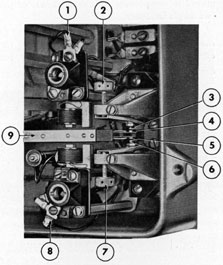
1. TERMINAL LUG A
2. ADJUSTABLE THUMB SCREW A
3. CONTACT SCREW A
4. CONTACT POINT A
5. CONTACT POINT B
6. CONTACT SCREW B
7. ADJUSTABLE THUMB SCREW B
8. TERMINAL LUG B
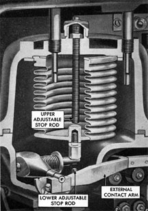
9. EXTERNAL CONTACT ARM Figure 5-25. External contact arm in center position.
the stationary contact levers are completely
open. Check to see that arm No. 9 is centered
between stationary contact points No. 3 and
No. 6. Manually move arm No. 9 upward and
downward to see that it works freely and returns to the center position. If it is in good
order, adjust the contact points as described
in Sections 5K3 and 5K4. If the contact arm
does not move freely or if it cannot be moved
to each side of its center position because the
internal lever strikes a stop rod, the interfering stop rod will have to be backed off
slightly in the manner described in Sections
5K9 and 5K10. If the stop rods do not interfere and the arm still does not return to the
center position, it will be necessary to attempt
to position the contact arm by adjusting the
52
1. PIPE PLUG OPENING
2. INNER CONTACT ARM CLAMP
3. CONTROL UNIT CASE
4. OUTER CONTACT ARM CLAMP Figure 5-26. End view of contact arm clamps.
contact arm clamps. This is performed in the
following manner:
position.Remove the pipe plug from the end of the
case to make the inner clamp accessible, as
shown in Figure 5-26. Slightly loosen the
inner clamp screws. Slightly loosen the clamp
screws from the outer clamp. Carefully hold
the arm in the center position with one hand,
and tighten the outer clamp screws so that
an equal space is maintained between the
clamp and the end of the arm. Then carefully
tighten the inner clamp screws in the same
manner. Clamp screws must be securely
tightened, and equal space must be maintained
between the inner surfaces of the contact arm
and the bearing plate at the bellows housing.
If the arm continues to bind, it is an indication of corrosion or damaged inner parts of
the bellows assembly or faulty bellows linkage installation. If this is the case, disassemble the bellows as described in Sections
5K12 through 5K16. Inspect, clean, and repair
parts if necessary, as described in Section
5K17. Assemble the bellows as described in
Sections 5K18 through 5K29. Adjust the contacts as described in Sections 5K3 and 5K4.
Reset the stop rods as described in Section
5K8, 5K9, and 5K10.
5K3. Adjusting the upper contact without
using the lamp. (See Figure 5-27.) Adjusting
the contacts without using a test lamp is the
regular procedure used. However, an alternate method of adjusting the contacts with
the use of a test lamp is also employed. Both
methods are explained.
Set the valves and vent cocks as shown
in Figure 5-24. This insures equal pressure
on the bellows. Deenergize or turn off the 2Y
circuit on the control board. Remove the
cover from the rotary distance transmitter,
and disconnect either the 2Y1 or the 2YY1 wire
from the left end of the terminal block. This
is done to prevent the pump from operating
while adjustments are being made. Energize
the 2Y circuit by turning the control panel
switch to the ON position. Manually push
down the external contact arm until the transtat brush arm in the rotary distance transmitter travels approximately one-third of its
distance from the lower limit switch. This
allows sufficient movement of the brush arm
while making adjustments. Turn down screw
No. 5 until the follow-up motor in the rotary
distance transmitter starts running smoothly.
When the upper contacts first touch, the follow-up motor will operate unevenly. Continue
to turn down screw No. 5 slowly, three-quarters of the distance between the holes in the
head of the screw (approximately 15 to 18
degrees). Secure screw No. 5 in this position
by means of the lock screw in front of the
contact mounting bracket.
5K4. Adjusting the lower contact without
using the lamp. (See Figure 5-2$.) Break the
electrical contact on the upper lamp socket
by loosening the terminal screw and removing one wire from the terminal. This is done
so that the transtat motor will operate when
both contacts are touching. Normally the
transtat motor will not operate when both
contacts are touching the: contact arm. Turn
up screw No. 6 until the follow-up motor in
the rotary distance transmitter just starts
operating, then back off screw No. 6 slowly,
three-quarters of the distance between the
holes in the screwhead (approximately 15 to
18 degrees). Secure screw No. 6 in this position by means of the lock screw in front of
53
1. LAMP
2. TERMINAL LUG A
3. TERMINAL LUG B
4. UPPER LAMP SOCKET
5. ADJUSTABLE THUMB SCREW A
6. CONTACT SCREW A
7. CONTACT POINT A Figure 5-27. Adjusting upper contacts by the lamp method
the contact mounting bracket. Reinstall the
wire terminal on the terminal of the upper
lamp socket. This is necessary in order that
the follow-up motor will run down. The follow-up motor should then run down until the
transtat brush arm hits its lower limit switch.
If the brush arm does not hit the lower limit
switch and the follow-up motor does not stop,
it is an indication that the contact points were
not set properly. Personnel will have to reset
the contact points, being very careful to
slowly turn the contact adjusting screws the
proper amount as discussed above.
5K5. Preparing the system before adjusting
contacts with the test lamp. This is an alternate method of adjusting the contact points.
Two lamps are provided to make this adjustment. These lamps are mounted in a bracket
in the upper right side of the control mounting plate. Use only one lamp when making
this adjustment. The other lamp is a spare
only. Set the valves and vent cocks as shown
in Figure 5-24, in order to insure equal pressure on the bellows. Deenergize, or turn off
the 2Y circuit switch on the control panel.
Remove the cover from the rotary distance
transmitter. Disconnect either the 2Y1 or
the 2YY1 wire from the left end of the terminal block in the rotary distance transmitter.
This is done to prevent the pump from operating while adjustments are being made.
Energize the 2Y circuit from the control panel. Manually push down on the contact arm
until the transtat brush arm travels approximately one-third of its total distance from
the lower limit switch. This allows sufficient
movement of the brush arm while making
adjustments. Move the wire from the upper
terminal to the lower terminal of the upper
lamp socket as shown in Figure 5-27. The lower lamp socket is prepared in the same manner as shown in Figure 5-28.
5K6. Adjusting the upper contact using the
lamp method. (See Figure 5-27.) Remove one
of the lamps from the bracket in the rear of
the case. Install the lamp in the upper socket.
Turn down screw No. 5 until the lamp burns
without flickering. Then slowly continue to
turn down screw No. 5 for three-quarters of
the distance between the holes on the screwhead
1. TERMINAL LUG A
2. TERMINAL LUG B
3. LAMP
4. CONTACT POINT
5. CONTACT SCREW B
6. ADJUSTABLE THUMB SCREW B
7. LOWER LAMP SOCKET Figure 5-28. Adjusting lower contacts
by the lamp method.
54
(approximately 15 to 18 degrees). Secure screw No. 5 in this position by means of
the lock screw on the upper contact bracket.
5K7. Adjusting the lower contacts, using the
lamp method. (See Figure 5-28.) Remove the
test lamp from the upper socket and install
it in the lower lamp socket. This breaks the
contact in the upper socket, and permits
proper adjustment of, the lower contact. Turn
screw No. 6 slowly upward until the lamp
glows; then slowly back off screw No. 6 until
the lamp does not glow. Continue to back off
screw No. 6 slowly for three-quarters of the
distance between the holes in the screwhead
(approximately 15 to 18 degrees). Secure the
screw in this position by means of the lock
screw in front of the mounting bracket. Remove the lamp from the socket and install it
in the carrying bracket back of the control
mounting plate. Remove the wires from the
upper and lower lamp socket terminals and
install them in their original position on the
sockets as shown in Figures 5-27 and 5-28. If
the follow-up motor in the rotary distance
transmitter does not drive the transtat brush
arm to the lower limit switch, it is an indication that the contacts are not properly adjusted, and that the operation of the adjusting
contact points will have to be repeated. Check
the setting of the upper and lower stop rods
and reset if necessary (see Sections 5K8, 5K9,
and 5K10) before operating the log. The contact setting made may be thrown off adjustment if the stops are incorrectly set.
5K8. Adjustable stop rods. (See Figure 529.) Two adjustable stop rods are provided in
the bellows assembly to limit the upward and
downward motion of the bellows, thus preventing possible damage to the interior parts
of the bellows housing, and to the contact
mechanism at times of excessive pressure differences. These pressure differences often
cause the bellows to stretch slightly from
the newly installed position and consequently
necessitate adjustment of the stops as well
as of the contact points. Older type bellows
assemblies are equipped with stop rods that
are only partly threaded throughout the
length of the rod. In the event that these old
Figure 5-29. Adjustable stop rods installed.
type rods become damaged or stripped, the
complete bellows assembly must be disassembled to remove them. In the newer type
of bellows assembly, the stop rods are
threaded throughout the entire length and
may be removed without dismantling the bellows housing.
5K9. Setting the lower adjustable stop rod.
(See Figures 5-29, 5-30, and 5-3l.) Remove the
cover from the control unit case. Unscrew
and remove the lower cap to make the lower
stop rod accessible. Remove the pipe plug
from the dower side of the case. Using the
socket wrench, loosen the lock nut that secures the stop rod in position. Place a finger on the contact arm and hold the arm
slightly downward. Turn the lower stop rod
inward (clockwise) until the stop rod contacts the bellows stud and starts to push the
contact arm upward. Continue to turn the
stop rod until the gap between the upper contact points is reduced to approximately 1/32-inch.
55
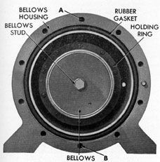
1. BELLOWS HOUSING
2. UPPER TOP CAP REMOVED
3. LOWER STOP CAP REMOVED Figure 5-30. Setting upper adjustable stop rod,
old installation.
Tighten the lock nut to secure the stop
rod in this position. Set the valves and vent
cocks as shown in Figure 5-42 (Position 7).
This causes the water to force the bellows
downward. The upper contacts should be
open approximately 1/32-inch. If the points
are not open this amount, reset the lower stop
rod. Make certain that the lock nut on the
lower stop rod is tight. Install the lower cap.
Turn the valves and cocks to the desired position.
5K10. Setting the upper adjustable stop rod.
(See Figure 5-31.) Remove the pipe plug from
the upper end of the case to make the stop rod
accessible. Remove the cap from the top of
Figure 5-31. Setting upper adjustable stop rod,
new installation.
the bellows housing. Using the socket wrench
as illustrated in Figure 5-31, loosen the lock
nut on the stop rod. Turn the stop rod downward (clockwise) while holding the contact
arm up against the upper contact screw until
the stop rod contacts the inside of the bellows
head. Continue to turn the stop rod until
the gap between the lower contacts is reduced
to approximately 1/32-inch; then tighten the
lock nut on the stop rod. Set the vent cocks
and valves as shown in Figure 5-42 (Position
3). Water pressure will now force the, contact arm upward. The lower contacts should
be open approximately 1/32-inch. If the
contacts are not open this amount, reset the
upper stop rod. Make certain that the lock
nut on the stop rod is tight. Install the cap
on the bellows housing. Turn the valves and
vent cocks to the desired position. Check the
operation of the system by operating it on
the static head as described in Section 5A2.
5K11. Checking the control unit after adjustment. Check the control unit, after adjusting the contact point and setting the stop
rods, in order to make certain that the unit is
operating properly. Perform the following
operations: Deenergize the 2Y circuit by
turning the switch on the control panel to the
OFF position. Reconnect the 2Y1 or 2YY1
56
circuit, whichever was previously disconnected, in the rotary distance transmitter. Energize the 2Y circuit. Operate the system on
the static head as described in Section 5A2.
The system should operate and register approximately 5 to 10 knots, depending on the
waterline above the unit. The transtat brush
arm should oscillate or hunt slightly. Turn
the valves and vent cocks to position (Figure
5-24). The transtat arm should drive down until the pump and motor stop, and should then
continue to drive down until the follow-up
motor is stopped by the limit switch. If satisfactory, turn the valves and vent cocks to the
secured position or the operating position,
whichever is desired.
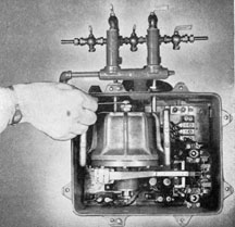
5K12. Removing the control unit from its
case. (See Figure 5-32.) Remove the cover
retaining screws and the cover. Remove the
static and dynamic hose from the nipples.
Break the piping unions and remove the two
hexagonal nipples. Disconnect the three wire
leads that connect the outside current source
with the terminal block and pull the wires to
one side out of the way. Remove the three
screws and toothed lock washers that secure
the mounting plate to the case, and lift the
plate and the assembled control unit out of
the case by means of the handles provided.
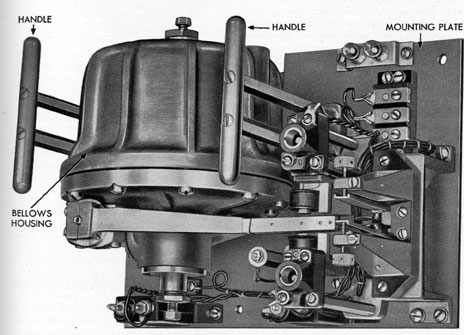
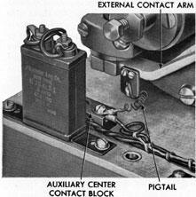
5K13. Removing the bellows assembly from
the plate. (See Figure 5-33.) Disconnect the
pigtail wire from the terminal on the auxiliary center contact block. Remove the handle
screws and the two handles. Unscrew and remove the handle studs that secure the bellows
housing to the mounting plate, and remove
the studs and complete bellows assembly. Be
careful that the contacts on the external contact arm are not damaged.
Figure 5-32. Control unit removed from case.
57
Figure 5-33. Pigtail wiring connection.
5K14. Removing the bellows housing corer.
(See Figure 5-34.) Remove the external arm
clamp retaining screws and clamps, and remove the contact arm. Remove the three
screws that secure the housing and cap with
the lower adjustable stop screw to the housing
cover. Drain the water from the bellows. Remove the cap screw from the bellows extension post, and the ten housing cover screws
and lift the housing cover from the assembly.
5K15. Disassembly of housing cover. (See
Figure 5-38.) Remove the shoulder screw that
secures the shaft seal bellows to the contact
lever shaft. Detach the two pillow blocks and
bearing assemblies from the housing cover
after removing the shoulder screws. (The external contact arm was removed previously.)
It may be necessary to tap the end of the
contact arm shaft lightly with a soft hammer
or wooden block to loosen the bearings and
sockets. Remove the contact lever shaft. Detach the bellows seal cap after removing the
three seal cap screws. Remove the shaft seal
bellows, bellows stud, and gasket.
5K16. Disassembly of the bellows housing.
(See Figure 5-43.) Remove the screws that
secure the bellows holding ring to the housing, and remove the ring. Lift the bellows and
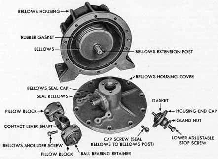
1. BELLOWS HOUSING COVER
2. GASKET
3. SEAL BELLOWS ASSEMBLY
4. CAP (BELLOWS SEAL)
5. CONTACT LEVER SHAFT
6. BELLOWS SHOULDER SCREW Figure 5-34. Bellows housing, cover removed.
the bellows gasket from the housing. Unscrew
and remove the cap, gland liner, packing, and
stop rod from the top of the housing.
5K17. Inspection and repair. Examine the
gaskets for cracks and torn edges. Replace
any damaged gaskets. Examine the contact
arm shaft for score marks. Remove any scoring with an oilstone or crocus paper. Examine
the threads of the adjustable stop rods. I the
threads are slightly damaged, chase them with
a stock and die. Replace badly damaged stop
rods. Carefully examine the pressure bellows
and shaft seal for cracks or pin holes. Fill the
bellows with kerosene and note any evidence
of seepage, which indicates cracks or holes.
Replace damaged bellows. If the bellows does
not leak, thoroughly clean the kerosene from
58
Figure 5-35. Bellows installed on housing.
the bellows to prevent damage to any rubber
parts. Carefully examine the bearings; Turn
the bearings slowly by hand. They should
turn freely. A clicking noise and binding indicate cracked balls.
5K18. Installing the pressure bellows in bellows housing. (See Figure 5-35.) Place the
bellows gasket in the recess provided in the
bellows housing. Carefully place the bellows
on the top of the gasket so that the bellows flange is properly seated over the gasket.
Place the bellows holding the ring over the
bellows. Align the mounting holes and install
the ten screws that secure the ring to the
housing. Check the length of the pressure
bellows with the bellows extension post installed. Adjust the free length of the bellows
so that the top of the extension post projects
31/32-inch outside of the outer (machined)
surface of the bellows housing.
5K19. Assembling and installing the bellows
housing cover. (See Figures 5-37, 5-38, and
5-39.) Mount the seal bellows and stud with
a gasket in the housing cover. Place the cover
with a rubber gasket on the bellows housing.
Then carry out the following procedure:
1. Align the seal bellows stud with the
bellows extension post, and loosely install the
cap screw that secures the seal bellows stud
1. BELLOWS HOUSING COVER
2. GASKET
3. SEAL BELLOWS ASSEMBLY
4. CAP (BELLOWS SEAL)
5. CONTACT LEVER SHAFT
6. BELLOWS SHOULDER SCREW Figure 5-36. Cutaway view of seal bellows
assembly.
to the bellows extension post. Tighten the seal
bellows cap retaining screw.
2. Assemble the ball bearing in the pillow
blocks (one to each block) and install the
ball bearing retainers on the pillow blocks.
Assemble the pillow blocks on the ends of
the contact lever shaft (one at each end), then
place the contact lever shaft in position over
the seal bellows and adjacent to the bellows
housing cover with the side of the shaft
marked TOP toward the cover. Secure the
pillow blocks to the cover with four screws
(two to each block).
3. Install the seal bellows shoulder screw
through the hole in the contact lever shaft,
and tighten the screw securely.
4. Tighten the cap screw that secures the
seal bellows stud to the bellows extension
post.
5. Assemble the lower adjustable stop
screw in the following manner: Install the
59
short screw into the gland nut. Slide the gland
liner on the stop screw with the concave surface of the liner facing away from the head
of the stop screw. Place sufficient packing
against the concave surface of the liner; then
screw the stop-screw assembly into the housing end cap. In replacing the packing, do not
use more than necessary, as too much will prevent the proper adjustment of the stop screw.
Be sure that the stop screw is well backed out.
Place the stop screw assembly in position on
the bellows housing cover, being sure that the
gasket is in place, and secure with the three
screws provided. Tighten securely.
6. Assemble the upper adjustable stop
screw in the housing cap in the same manner
as the lower stop screw. Be sure that the stop
screw is well backed out of the cap. Install
the housing cap with its assembled stop screw
on top of the bellows housing.
5K20. Checking the bellows assembly for
friction. Temporarily install the external
contact arm and clamps on the contact arm shaft.
Move the contact arm upward and downward.
If the arm operates stiffly in one direction,
unscrew the adjustable stop rod on the stiff
side of the arm. Set a small tool or block at
the outer end of the external contact arm to
act as a marker. Manually move the contact
arm first in one direction and then in the
opposite direction, approximately 1/32-inch
each way. The arm should return to its original position if the bellows components were
properly installed. If the bellows contact arm
does not return to its original position, the
bellows should be disassembled, and the cause
of the binding determined and eliminated.
Remove the contact arm and clamps from the
bellows cover. Install the balance of the cover
screws. Place the bellows subcover and its
gasket in position on the housing cover, and
secure with the six screws provided.
5K21. Installing external contact arm. (Figures 5-40 and 5-41.) Place the external contact
Figure 5-37. Bellows housing assembly, old installation.
60
Figure 5-38. Bellows housing cover with housing
end cap and stop rod removed, new installation.
arm in position on the contact lever shaft. Install the contact, arm clamps, making certain
that the assembly marks on the clamps correspond with those on the arm. Install the
four zinc-plated steel screws (two to each
clamp) that secure the arm clamps to the
external contact arm. Be sure that there is
Figure 5-39. Bellows housing cover assembled,
new installation.
clearance between each clamp and the adjacent ball bearing retainer.
5K22. Installing the bellows assembly on the
mounting plate. (See Figures 5-32 and 5-33.)
Carefully place the bellows housing on the
mounting plate. Align the mounting holes
1. BELLOWS HOUSING
2. BELLOWS HOUSING COVER
3. BELLOWS HOUSING COVER SCREW
4. EXTERNAL CONTACT ARM
5. HOUSING END CAP SCREW
6. HOUSING END CAP
7. GLAND NUT
8. LOWER ADJUSTABLE STOP SCREW (SHORT)
9. PIGTAIL
10. BALL BEARING RETAINER
11. EXTERNAL CONTACT ARM CLAMP
12. CONTACT ARM CLAMP SCREW
13. PILLOW BLOCK RETAINING SCREW
14. PILLOW BLOCK
15. BELLOWS SEAL CAP
16. CONTACT LEVER SHAFT
17. BELLOWS SHOULDER SCREW
Figure 5-40. Bellows housing assembly.
61
1. PIPE PLUG OPENING
2. INNER CONTACT ARM CLAMP
3. CONTROL UNIT CASE
4. OUTER CONTACT ARM CLAMP Figure 5-41. End view of contact arm clamps.
and install the four handle studs that secure
the housing to the plate. Remove the terminal
screw from the right side of the auxiliary
center contact block. Lift of f the wire, and
place the pigtail connection on the block.
Place the wire over the pigtail and install the
terminal screw. Place the handles in position
on the studs, and install the handle retaining
screws.
5K23. Aging the bellows. (Figure 5-42.)
Aging the control unit bellows is necessary
any time a new bellows is installed, or if the
old bellows has been bent out of its normal
position. The bellows, like any metal spring,
will return to a certain position when an applied pressure is released, unless the pressure
has been sufficient to bend it and cause the
bellows to set in a new position. If there are
stresses retained in the metal from bending or
stretching, the bellows will not return at once
to the original position, but may creep slowly
to that point. To be certain that all stresses
are removed from the bellows it should be
put through an aging operation. The aging
operation consists of impressing a pressure
first on the inside of the bellows and then on
the outside, while gradually reducing the
impressed pressure to zero.
Figure 5-42. Valve positions for aging the bellows.
*22. CAP SCREW (SEAL BELLOWS TO BELLOWS POST).
23. BELLOWS HOUSING COVER SCREW.
*24. GASKET.
*25. SEAL BELLOWS.
*26. BELLOWS SEAL CAP.
*27. SEAL CAP SCREW (BRONZE 10-32 X 1/2 FLAT HEAD).
*28. PILLOW BLOCK RETAINING SCREW.
*29. BALL BEARING RETAINER SCREW (BRONZE 4-36 X 3/8 FLAT HEAD).
*30. BALL BEARING RETAINER.
*31. BALL BEARING.
*32. PILLOW BLOCK.
33. CLAMP RETAINING SCREW.
34. EXTERNAL CONTACT ARM CLAMP.
*35. CONTACT LEVER SHAFT.
*36. BELLOWS SHOULDER SCREW.
* Indicates replacement parts necessary to modify old bellows.
Figure 5-43. Exploded view of bellows assembly.
63
The equipment necessary to perform the
aging operation is a 2-gallon tank with pressure gage, and connections capable of withstanding a pressure of 20 pounds per square
inch. A pressure storage tank such as that
illustrated in Figure 7-1 may be used. Fill the
pressure tank approximately one-half full of
water. Connect the line from the tank to the
dynamic and static connections of the control
unit. Vent the control unit. Make certain that
the adjustable stop rods have been positioned
by turning in each rod until it touches the
bellows and then backing off exactly two full
turns so as to have the movement on each side
of the bellows equal. Loosen the contact arm
clamps. With valves and vent cocks in position as shown in Figure 5-24, build up a pressure of 20 pounds per square inch in the tank.
Follow the sequence of valve operations as
shown in Positions 1 to 9 (Figure 5-42),
being careful to permit all the water to flow
from the bellows before changing the valves
and cocks to the next position. Repeat this
operation until the pressure in the tank
reaches zero.
5K24. Installing the control unit in its case.
(See Figure 2-7.) Lift the control unit into
the control unit case, and secure with the
three screws and lock washers. Connect the
lugs on the ends of the electrical leads to the
terminal block on the upper right of the
mounting plate.
5K25. Installing the piping assembly. (See
Figure 2-7.) Loosen the gland nuts on top of
the control unit case; and place the nipples
through the top of the case and into the top
of the bellows housing, using a small amount
of pipe compound on the threads. Tighten
the nipples securely so that the tops of the
lower half of the unions are parallel. Place
the valve piping assembly in position on top
of the nipples, with the copper tubes inside
the nipples, and tighten the unions securely.
Test the complete unit for leaks with 300
pounds per square inch of water pressure.
(The bypass valve must be open.) Place the
hose- from the rodmeter on the static nipple
(right-hand). Place the hose from the pump
on the left-hand nipple and tighten the hose
clamps. Fill the system with water and vent
Figure 5-44. Piping assembly, old installation.
it as described in Section 3A3. Center the
contact arm, adjust the contact points and
stop screws (see Sections 5K2, 5K3, 5K4,
5K9, and 5K10). In this case, the top contact
adjusting screw is advanced only 1/2-hole, and
the bottom screw is backed off 1/2-hole. The
stop screws in the modified control unit are
adjusted in the same manner as the stop rods
in the older installation, except that the special stop rod wrench and screwdriver are not
needed. Place the cover in position on the
control unit case and secure with the cover
retaining screws.
Figure 5-45. Piping assembly, new installation.
64
L. CONTROL UNIT PIPING
5L1. Description of modified control unit
piping assembly.Most submarine control units
are equipped with the conventional type of
piping assembly as shown in Figure 5-44.
Some, however, are equipped with a modified
piping assembly that contains a safety pressure relief assembly as shown in Figure 5-45.
This is a safety feature which protects the
bellows when the pressure difference across
the bellows exceeds approximately 25 pounds
per square inch. Such a difference will
occur if a hose should blow off, or if the unit
is vented incorrectly when submerged. When
the pressure difference exceeds 25 pounds
per square inch, the diaphragm will rupture,
4. Install the vent cocks in the T-fittings.
Use pipe compound.
5. Assemble the left-hand street ell,
nipple, and fixed block, and install the left-hand street ell in the left-hand T-fitting. Use
pipe compound.
6. Assemble the pipe fitting into the
right-hand street ell, using pipe compound.
7. Slide the gland nut, bakelite washer,
rubber slip joint washer, and movable block
onto the pipe nipple.
8. Align the fixed and movable blocks,
and loosely install the four lower movable
block screws.
thereby equalizing the pressures on both sides
of the bellows and protecting the bellows
from distortion.
5L2. Modifying the control unit piping assembly. (See Figures 5-45 and 5-46.) Modify
the control unit piping assembly as described
in the following steps:
1. Unscrew and remove the vent cocks.
2. Remove the elbows, but leave the elbow
nipples installed in the cross-connector.
3. Install T-fittings in place of the elbows
in the cross-connector. Use only a small
amount of pipe compound on the threads.
9. Insert the platinum diaphragm into
the gap between the blocks. Make certain that
the diaphragm is properly aligned within the
blocks to prevent damage to the diaphragm
when the remainder of the screws are
installed in the blocks.
10. Install the remainder of the block retaining screws and tighten all screws.
11. Hold the blocks with a wrench and
tighten the gland nut securely.
12. Test the complete unit for leaks with
300 pounds per square inch of water pressure.
The bypass valve must be open.
65
1. SELF-SYNCHRONOUS TRANSMITTER
2. FOLLOW-UP CONTACT ASSEMBLY
3. SLIP RING AND CONTACT ASSEMBLY
4. SELF-SYNCHRONOUS REPEATER
5. UPPER DIFFERENTIAL GEAR
6. DIFFERENTIAL SPIDER
7. LOWER DIFFERENTIAL GEAR
8. CONSTANT SPEED MOTOR AND DISK
9. FRICTION ROLLER AND PINION
10. LEAD SCREW DRIVING MOTOR
11. YOKE
12. LEAD SCREW
Figure 5-47 Cutaway view of master speed indicator.
66
5L3. Testing for leaky or punctured diaphragm. Operate the system on the static
head as described in Section 5A2. If water
drips continuously out of the open vent cock,
it is an indication that the diaphragm is punctured.
5L4. Replacing a damaged diaphragm. (See
Figure 5-45.) Hold the movable and fixed
blocks with a wrench, and loosen the gland
nut. Remove the two top screws from the
movable block, and loosen the remainder of
the block screws. Separate the movable block
from the fixed block sufficiently to remove
the damaged diaphragm. Remove the damaged
diaphragm. Insert the new diaphragm between
the blocks, making certain that it is aligned
properly within the blocks. The diaphragm
must be 0.0008 inch thick (Pitometer Log
Corporation S1452B). Install the two top
movable block retaining screws, and tighten
all screws securely. Test for a leaky diaphragm as described in Section 5L10.
M. MAINTENANCE OF MASTER SPEED INDICATOR
5M1. General information. Provision has
been made for removal of the complete unit
from the case for purposes of inspection and
test of the master speed indicator. Subassemblies of the unit are constructed so that
they may be replaced as units. Whenever any
of the components are removed, it is necessary that the instrument be recalibrated.
5M2. Replacing the pointer and dial. (See
Figure 5-47.) Remove the cover retaining
screws, and remove the case cover. Remove
the hub cap from the pointer hub. Remove the
screw that secures the pointer hub to the,
speed transmitter shaft and remove the pointer assembly. Remove the six screws that secure the dial to the mounting studs and remove the dial. To install the dial, position
it on the mounting studs and install the dial
retaining screws. Place the pointer on the
shaft of the transmitter shaft, and secured it
with the screw provided. Set the pointer to
exact zero, if necessary, as described in Sections 5M51 and 5M52. Install the pointer hub
cap. Place the cover in position on the case
and install the cover retaining screws.
5M3. Testing the lead screw drive motor.
(See Figure 5-48.) Test the operation of the
lead screw drive motor in the following manner: Remove the cover from the case. Disconnect the lead from the center terminal of the
motor. This terminal is marked C. Rotate the
gear by hand until the pointer reads several knots. Using a screwdriver, alternately
short circuit the terminals marked CW and
CCW with the center terminal. The motor
will run first clockwise and then counterclockwise, if it is operating properly. If the
motor is binding, or inoperative, replace it.
5M4. Removing the lead screw drive motor.
(See Figure 5-48.) Remove the cover from the
case. Disconnect the wires from the motor
terminal, and tag the wires for ready identification. Remove the three screws and toothed
lock washers that secure the motor bracket
to the main mounting plate, and remove the
motor assembly.
5M5. Replacing the lead screw drive motor.
(See Figure 5-49.) Remove the lead screw
drive motor (see Section 5M4). Remove the
two fillister head screws that position the
Figure 5-48. Lead screw drive motor removed.
67
motor in its bracket. Remove the two screws,
lock washers, and nuts, and remove the motor
from its mounting bracket as shown in Figure
5-50. Remove the reduction gear stud nut. Remove the retaining pin and washer from the
old motor as shown in Figure 5-50, and remove
the gears from the motor. Remove the stud
nut from the new motor. Remove the retaining
Figure 5-49. Replacing lead screw drive motor,
Step 1.
pin and washer from the micarta gear son
the new motor, as the washer interferes with
the installation of the reduction gear assembly. Place the reduction gear assembly from
the old motor on the shaft of the new motor,
and install the stud nut. Install the washer
and retaining pin on the micarta gear shaft.
Place the new motor with its assembled reduction gear as shown in Figure 5-51 in position
in the motor mounting bracket. Install the
two fillister head screws that position the
motor in its bracket. Install the two screws,
lock washers, and nuts that secure the motor
(Figure 5-49).
Figure 5-51. Replacing lead screw drive motor Step 3.
5M6. Installing the lead screw drive motor.
(See Figure 5-48.) Place the lead screw drive
motor and its attached bracket in position on
the main mounting plate and install the three
screws and toothed lock washers that secure
the motor assembly to the mounting plate.
Connect the wires to the terminal on the motor. Test the operation of the motor as described in Section 5M3.
5M7. Replacing the mileage counter. (See
Figure 5-52.) Turn the operating shaft of the
dimmer rheostat so that its forked end clears
the rheostat shaft extension. Remove the 10
mounting screws that secure the main mounting plate to the case, and lift the unit out of
the case. Disconnect the outside source lead
wires from the terminal block. Remove the
pointer and dial (see Section 5M2). Remove
the four screws that secure the mileage counter to the top mounting plate, and remove the
counter. Transfer the counter gear to the
new counter. Place the new counter in position on the top mounting plate, and install the
four counter retaining screws. Install the
dial and pointer (see Section 5M2). Place the
unit in its case (see Section 5M50).
5M8. Removing the top mounting plate. (See
Figure 5-52.) Remove the mileage counter
(see Section 5M8). Remove the tapered pin
from the counter driving worm as shown in
Figure 5-52, and remove the worm from the
self-synchronous repeater shaft extension.
Unscrew and remove the top support stud
from the upper left corner of the mounting
plate. Remove the screws and lock washers
that secure the top mounting plate to the
studs on the main mounting plate. Remove the
two handle retaining screws from the upper
right handle. The handle screws are staked at
assembly. Swing the top mounting plate to
one side out of the way.
5M9. Removing the brush block assembly.
(See Figure 5-53.) Remove the top mounting
plate (see Section 5M8). Remove the two
screws that secure the brush block as to the studs on the main mounting plate, and
carefully remove the brush block to disengage
the brushes from the slip rings of the slip
ring and contact assembly. Disconnect the
wires from the brush block, and tag them for
ready identification.
5M10. Replacing the spiral take-up spring.
(See Figures 5-53 and 5-54.) Remove the top
mounting plate as described in Section 5M8.
Unscrew and remove the pin screw from the
second follow-up driving gear at the left side
of the spring. Loosen the setscrew that secures this second follow-up driving gear to
the jackshaft. Hold the large follow-up driving gear while lifting the small follow-up
1. MAIN MOUNTING PLATE
2. TOP BRACKET
3. TAKE-UP SPRING HOOK
4. SECOND FOLLOW-UP GEARS
5. BEARING PLATE
6. SPIRAL TAKE-UP SPRING
7. BRUSH SPRING
8. FOLLOW-UP CONTACT ASSEMBLY
9. BRUSH BLOCK
10. BRUSHES
11. SLIP RING AND CONTACT ASSEMBLY
12. DIFFERENTIAL TOP BRACKET
13. JACKSHAFT
14. FIRST FOLLOW-UP DRIVEN GEAR Figure 5-53. Slip ring and contact assembly,
brush block removed.
gear from the jackshaft to prevent the spring
from unwinding too rapidly. Gradually release the large gear to permit the spiral takeup spring to unwind gradually. Disengage
the end of the spring from the hooks provided
on the top mounting bracket and on the hub
of the large second follow-up driving gear.
Install the new spring in the following manner:
70
1. SPRING HOOK
2. BEARING PLATE
3. SPRIAL TAKE-UP SPRING
4. LARGE SECOND FOLLOW-UP DRIVEN GEAR
5. JACKSHAFT (SMALL SECOND FOLLOW-UP DRIVING GEAR REMOVED) Figure 5-54. Installing spiral take-up spring.
Engage the hole in one end of the spring
in the hook on the hub of the large second
follow-up driving gear as shown in Figure 554. Turn the large gear by hand to wind up
the spring on the gear hub. Hook the loose
end of the spring on the hook provided on the
top mounting bracket as shown in Figure 5-54. Turn the gear until the spring is tightly
wound, and then back off the gear three-quarters of a turn to give the spring the proper
tension. Hold the large gear and spring in
this position while installing the small second follow-up driving gear on top of the jackshaft. Align the pin screw hole and install
the pin screw and setscrew to secure the
small gear on the jackshaft.
5M11. Removing the follow-up contact assembly. (See Figure 5-55.) Remove the brush
block assembly (see Section 5M9). Remove
the spiral take-up spring (see Section 5M10).
Remove the starting condenser from the back
of the main mounting plate as described in
Section 5M47. This makes the top bracket
mounting screws accessible. Remove the two
top bracket retaining screws and lock washers. Loosen the mounting screws on the differential top bracket, differential bottom
bracket, and the main mounting bracket, so
that the brackets can be slightly lifted to allow for the clearance of the dowel pins on the
top bracket. Lift all the brackets away from
the main mounting plate and remove the top
bracket with its assembled follow-up contact
assembly as shown in Figure 5-55. Remove
the lock nut, tension spring, washer, and the
follow-up contact assembly from the follow-up shaft.
5M12. Removing the slip ring and contact assembly. (See Figure 5-55.) Remove the follow-up contact assembly as described in Section
5M11, in order to get proper clearance for
the removal of the slip ring and contact assembly. Remove the pin screw and loosen the
setscrew that secures the slip ring and contact
assembly to the differential shaft. The slip
ring and contact assembly is removed as a
unit (see Figure 5-57).
5M13. Repairing the follow-up contact assembly. (See Figure 5-56.) Under ordinary
circumstances the follow-up contact assembly
is replaced as a unit. However in an emergency the follow-up contact can be replaced
as follows: Remove the screws from the bakelite disk, and unsolder the lead wire from the
contact arm. Place the new contact arm in
position on the bakelite disk, and secure with
the screws provided. Solder the lead wire to
the contact.
5M14. Repairing and adjusting the slip ring
and contact assembly. (See Figure 5-57.)
Smooth the contact points with a jeweler's
file, and remove fine particles; oil, or grease
with clean cloth or paper. If .the contact
points are badly worn, or pitted, unscrew the
contact screws from their mounting brackets,
and install new contact screws. At assembly
there should be a space of 1/32-inch between
the contact screw point and the follow-up
71
1. FOLLOW-UP CONTACT, ASSEMBLY
2. SLIP RING AND CONTACT, ASSEMBLY
3. DIFFERENTIAL TOP BRACKET
4. MAIN MOUNTING BRACKET
5. LEAD SCREW, ASSEMBLY
6. FIRST FOLLOW-UP DRIVEN GEARS
7. JACKSHAFT
8. TOP BRACKET
9. SPRING SHIELD
Figure 5-55. Removing follow-up contact assembly and top bracket.
Figure 5-56. Follow-up contact assembly removed.
contact when one of the contact points is
touching the contact arm. Adjust for this
clearance by turning the contact screws
Figure 5-57. Slip ring and contact assembly removed.
inward or outward until the desired clearance
is obtained. Clean the slip rings with crocus
paper.
5M15. Cleaning and repairing brushes. (See
Figure 5-53.) The brushes on the brush block
should be cleaned with crocus paper. The
72
brushes should move freely on their mounting
studs without binding and should contact
both sides of the slip ring. If they do not
contact the slip ring properly, replace the
brush springs.
5M16. Removing the differential and lead
screw assemblies. (See Figures 5-59 and 5-60.)
Since all mounting brackets on the forward
face of the main mounting plate are doweled,
it is necessary to raise all the brackets simultaneously to clear the dowel pins without distorting the connecting parts. Remove the
follow-up contact assembly (see Section
5M11). Remove the slip ring and contact assembly (see Section 5M12). Remove the lead
screw drive motor (see Section 5M4). Remove
all the bracket mounting screws. Lift the jack
1. TAKE-UP SPRING
2. OIL WELL COVER AND SPRING SUPPORT
3. END PLATE
4. ROLLER SHAFT AND PINION
5. FRICTION ROLLER
6. LEAD SCREW YOKE
7. LIMIT SWITCH OPERATING SCREWS
8. ROLLER AND PIVOT Figure 5-58. Lead screw yoke assembly removed.
screw assembly out of the differential top
bracket. Carefully lift off the differential
top bracket, differential bottom bracket, and
the main mounting bracket in such a manner that the connecting parts will not be distorted or sprung. Loosen the setscrew that
secures the guide rod in the differential bottom bracket, and pull the guide rod out of its
brackets. Remove the differential from the
top and bottom mounting brackets. Remove
the pin screw and loosen the setscrew that
secures the lead screw driven gear to the bottom of the lead screw, and remove the gear.
Pull the lead screw assembly out of the main
mounting bracket.
5M17. Disassembly of the lead screw assembly. (See Figures 5-58 and 5-61.) Unscrew
and remove the lead screw and follow-up pinion from the lead screw yoke. Remove the end
plate retaining screws, end plate, thrust
spring washer, and ball bearing from the upper end of yoke. Push the roller and pinion
upward as shown in Figure 5-61, and remove
them from the yoke. The ball bearing on the
opposite end of the yoke is removed by
removing the end plate and thrust spring
washer.
5M18. Cleaning and repairing the lead screw
assembly.Do not attempt to remove the friction roller from the roller shaft and pinion.
Replace this assembly as a unit. Thoroughly
clean all parts in Navy-approved cleaning
fluid. Examine the friction roller and guide
rod roller for flat spots. The diameter of the
friction roller should be 1.2505 inches maximum and 1.2480 inches minimum. If the roller
is smaller than 1.2480 inches, replace the complete roller shaft and pinion assembly.
5M19. Assembling the lead screw assembly.
(See Figures 5-58 and 5-61.) Install the lower
end plate on the yoke. Place the ball bearing
in the yoke with the open face of the bearing
upward. Place the friction roller shaft and
the pinion assembly in position in the yoke.
Install the upper ball bearing in the yoke with
the open end of the bearing toward the roller
shaft. Place the thrust spring washer on the
bearing with the protruding section of
the washer away from the bearing. Install the
end plate and the end plate retaining screws.
73
Figure 5-59. Master speed indicator, top mounting plate removed.
74
1. DIFFERENTIAL TOP BRACKET
2. DIFFERENTIAL SHAFT
3. DRIVEN SPRIAL GEAR
4. DIFFERENTIAL END PLATE AND GEAR HUB
5. UPPER DIFFERENTIAL FACE BEVEL GEAR
6. LEAD SCREW AND FOLLOW-UP PINION
7. TAKE-UP SPRING
8. SPIDER
9. DIFFERENTIAL BEVEL PINION
10. SPUR GEAR (STANDARD SPEED)
11. LOWER DIFFERENTIAL FACE BEVEL GEAR
12. DIFFERENTIAL BOTTOM BRACKET
13. ROLLER AND PIVOT
14. LIMIT SWITCH OPERATING SCREWS
15. LEAD SCREW YOKE
16. DUST WASHER
17. GUIDE ROD
18. BALL BEARING
19. MAIN MOUNTING BRACKET
20. LEAD SCREW DRIVEN GEAR
21. PIN SCREW
Figure 5-60. Lead screw and differential partially disassembled.
75
Screw the lead screw and follow-up pinion
into the lead screw yoke so that the lead screw
is installed approximately halfway into the
yoke.
1. END PLATE SCREW
2. END PLATE
3. THRUST SPRING WASHER
4. BALL BEARING
5. ROLLER SHAFT AND PINION
6. FRICTION ROLLER
7. LEAD SCREW YOKE
8. TAKE-UP SPRING
9. OIL WELL COVER AND SPRING SUPPORT Figure 5-61. Roller shaft and pinion removed from yoke.
Figure 5-62. Pressing out short end of differential shaft.
5M20. Disassembly of the differential assembly. (See Figures 5-60, 5-62, and 5-63.)
Remove the four spur gear retaining screws,
and the spur gear from the lower differential
bevel gear. Remove the screw, retaining plate,
bearing, and differential bevel pinion from
the spider shaft. Support the differential bevel
face gear which is mounted on the short differential shaft on bakelite or other soft blocks
to protect the gear teeth. Do not use brass or
steel blocks. Using a brass rod as shown in
Figure 5-62, press out the shaft from the bearing. Remove the bearing from the gear. The
bearings are a light press fit on the shaft, and
a hand press fit in the gear housing. Remove
the four screws that secure the differential
end plate and gear hub to the upper differential bevel face gear, and lift off the plate and
76
gear hub with the assembled driven spiral
gear. Place the special pilot over the long end
of the differential shaft as shown in Figure
5-63. Support the gear teeth on the bakelite
blocks on the bed of an arbor press. Press the
shaft out of the bearings. Remove the bearing
from the gear housing.
5M21. Cleaning, inspection, and repair of
the differential assembly. (See Figure 5-60.)
Thoroughly clean all parts of the differential
assembly with Navy-approved cleaning fluid.
Dry all parts thoroughly. Replace all bent,
broken, or heavily scored parts. If the differential shaft is lightly scored, remove the
score marks with an oilstone, and polish with
crocus paper. Visually inspect the bearings,
and replace any cracked or otherwise damaged
bearings. Remove light nicks from the gear
Figure 5-63. Pressing out long end of differential
shaft.
Figure 5-64. Installing bearing on short end
of differential shaft.
teeth with a knife-edge file. Gears with
cracked or chipped teeth should be replaced.
5M22. Installing the gear and bearing on the
short end of the differential shaft. (See Figure 5-64.) Support the shoulder on the long
end of the differential shaft in a special bed
plate on an arbor press as shown in Figure
5-64. This is necessary in order to prevent
bending the shaft. Place one of the differential bevel face gears over the short end of
the shaft with the gear teeth facing the spider.
Place one of the two identical ball bearings
over the short end of the shaft, and align the
bearing with the opening in the gear housing.
Using a special pilot as shown in Figure 5-64,
press the bearing into the gear housing. Remove the assembly from the arbor press.
77
Place the large spur gear over the short end
of the shaft and install the four retaining
screws that hold the spur gear to the hub of
the bevel face gear.
5M23. Installing the gear and bearing on the
long end of the differential shaft. Place the
second bevel face gear on the long end of the
differential shaft with the gear teeth toward
the spider. Place the second ball bearing over
the long end of the shaft and align the bearing with the opening in the gear housing.
Using a special pilot as shown in Figure 5-64,
press the bearing on the shaft and into the
gear housing. Remove the assembly from the
arbor press. Place the differential end plate
and gear hub assembly over the bearing, and
install the four screws that secure the end
plate and gear hub assembly to the bevel face
gear.
5M24. Installing the differential bevel pinion. (See Figure 5-60.) Place the bevel pinion
ball bearing in the differential bevel pinion.
Place the gear and bearing on the shaft of the
spider with the gear teeth meshed with those
of the two bevel faced gears. Install the retaining plate and screw to secure the gear and
bearing to the spider shaft.
5M25. Installing the lead screw and differential assemblies. (See Figures 5-59 and 5-60.)
When installing the lead screw assembly
and/or the differential assembly on the main
mounting plate, it is necessary that the brackets be placed in their dowel pin holes without
being fastened down to the plate. The close
fits of the brackets and shafts make it necessary to lift the brackets slightly as the shafts
are installed to allow clearance for the various
dowel pins. Place the lead screw ball bearing
in the main mounting bracket. Place the dust
washer over the lower end of the lead screw,
and insert the lead screw through the bearing
and mounting bracket. Place the lead screw
driven gear on the lower end of the screw and
secure with the pin screw and the setscrew.
Slide the guide rod through the opening in
the main mounting bracket and into the opening in the differential bottom bracket. Secure
the guide rod in the differential bottom
bracket with a setscrew. Place the lower end
of the differential shaft into the bottom
bracket with the spur gear in mesh with the
friction roller shaft and pinion. Place the
differential top bracket over the long differential shaft and over the lead screw pinion.
Loosely set the dowel pins of the top bracket
in the mounting plate dowel pin holes. Place
the jackshaft and gear in position in the differential top bracket with the first follow-up
gear on the jackshaft in mesh with the lead
screw pinion. Install the slip ring and contact
assembly (see Section 5M32). Install the follow-up contact assembly as explained in
Sections 5M33 and 5M34. Install the bracket
retaining screws loosely. Do not tighten the
bracket screws at this time, as the brackets
will have to be lifted slightly in order to install the top mounting bracket.
1. SELF-SYNCHRONOUS REPEATER (60 R.P. MILE)
2. STARING CONDENSER FOR CONSTANT SPEED MOTOR
3. SELF-SYNCHRONOUS TRANSMITTER (SPEED)
4. CONSTANT SPEED (SYNCHRONOUS) MOTOR
5. PLUG-JACK CONNECTION
6. PLUG-JACK CORD (SPARE PARTS BOX) Figure 5-65. Rear view of master speed indicator
showing jack plug connections.
78
Figure 5-66. Removing friction disk and spider.
5M26. Removing the constant speed motor.
(See Figures 5-65, 5-66, and 5-67.) Remove
the lead screw and differential assemblies
from the main mounting plate as explained
in Section 5M16. Loosen the two setscrews
that secure the friction disk and spider to the
motor shaft and lift off the spider and disk
assembly. Do not attempt to turn the disk on
the motor shaft as the teeth on the micarta
worm gear will be stripped. Disconnect the
three electrical leads from the terminal block
on the back of the mounting plate. These
wires and terminals are marked W1, S1, and
S2. Remove the four screws that secure the
motor to the mounting plate from the front
of the mounting plate, and remove the motor.
5M27. Removal and disassembly of the reduction gear housing. (See Figures 5-68 and
5-69.) Remove the three screws that secure
the reduction gear housing assembly to the
motor, and remove the housing. Remove the
packing nut and felt washer from the housing.
Remove the adjusting screw and nut, fiber
washer, felt washer, spring, and ball from the
opposite end of the high speed shaft. Remove
the pin screw and loosen the setscrew that
secures the worm gear on the shaft. Carefully pull the slow speed shaft from its housing, and lift out the worm gear, spacer washer,
and spacer.
5M28. Cleaning, inspection, and repair of the
reduction gear assembly. (See Figure 5-69.)
Thoroughly clean all parts with Navy-approved cleaning fluid. Visually inspect the
felt and fiber washers for torn edges or other
damage. Replace the damaged washers. Examine the worm gear for chipped or broken
teeth, and replace the damaged worm gear.
Examine the slow speed shaft for score marks.
Remove light score marks with an oilstone,
and polish with crocus paper.
5M29. Replacing the shaft bearings. (See
Figure 5-68.) Bearings are replaced if they
become pitted due to corrosion, or if they are
damaged. Remove the shaft bearings in the
following manner: Remove the worm gear
housing (see Section 5M27). Remove the four
screws, two felt retainers, and felt washer
Figure 5-67. Constant speed motor removed.
79
1. END PLATE SCREW
2. END PLATE
3. SHIM
4. BALL BEARING
5. FELT WASHER
6. FELT RETAINERS
7. REDUCTION GEAR HOUSING
8. LOCK NUT
9. SCREW
10. SHAFT FOR FRICTION DISK AND SPIDER
11. WORM ON MOTOR SHAFT
12. TERMINAL LUGS Figure 5-68. Constant speed motor partially disassembled.
from the reduction gear end of the shaft. Remove the four screws, end plate, and shun
from the opposite end of the shaft. In the
event that the bearings will not come off the
shaft by tapping, it will be necessary to remove the armature assembly as follows:
Remove the motor back and shield, and pull
the armature assembly from the motor frame.
Remove the bearings from the shaft with a
bearing puller. Press the new bearings into
position on the shaft. Install the armature
assembly into the motor frame, and install the
back end shield. Install the shim and end
plate. Install the felt washer and two felt
retainers on the reduction gear end of the
motor. Install the worm gear housing (see
Section 5M30).
5M30. Assembly and installation of the gear
housing. (See Figures 5-68 and 5-69.) Install
the felt washer in the packing nut, and install
the packing nut on the gear housing. Place
the spacer, spacer washer, and worm gear in
approximate position in the gear housing. Insert the slow speed shaft into the housing,
through the reduction gear, spacers, and packing nut. Align the pin hole in the shaft and
gear, and install the pin screw and setscrew
to secure the reduction gear to the shaft. Install the thrust plate, ball, spring, felt washer,
fiber washer, and adjusting screw and nut on
the opposite end of the gear housing. Place
the reduction gear housing in position on the
motor, being sure to carefully engage the
teeth of the worm and reduction gear. Secure
with the three screws and toothed lock
washers.
5M31. Installing the constant speed motor.
(See Figures 5-65, 5-66, and 5-67.) Place the
constant speed motor in position on the back
of the main mounting plate, with the dowel
pins on the motor base inserted into the dowel
pin holes in the mounting plate. Install the
four screws from the front of the plate which
secure the motor to the plate. Connect the
three wire terminals to the terminal block on
the block on the rear of the mounting plate.
Terminals are marked W2, S2, and S1. When
a new motor is to be installed, the motor is
received without terminal lugs on the wire
end. The wires are tagged for identification,
and the lugs are installed in the same manner
as an old motor wiring. Install the friction
disk and spider on the motor shaft, and secure
with the two setscrews provided. Install the
lead screw and differential assemblies as explained in Section 5M25.
5M32. Installing the slip ring and contact assembly. (See Figures 5-55 and 5-57.) Place
the slip ring and contact assembly on the
upper end of the differential shaft. Align the
pin screw holes and install the pin screw.
Install the setscrew that secures the assembly
on the differential shaft.
5M33. Installing the follow-up contact assembly. (See Figures 5-55 and 5-56.) Place
the follow-up contact assembly on the follow-up shaft with the contact arm located between
the contact points of the slip ring and the contact assembly. Install the tension spring,
washer, nut, and lock nut on the follow-up
shaft in such a manner that approximately
three threads of the contact shaft will be
visible when the lock nut is installed. This
will put the proper tension on the spring.
5M34. Installing the top mounting bracket.
(See Figure 5-55.) Place the top mounting
bracket with its assembled follow-up contact
assembly in position on the main mounting
plate by inserting the dowel pins of the
bracket into the dowel pin holes provided in
the main mounting plate. Secure the bracket
to the plate with the two screws and lock
washers provided. Install the starting condenser on the back of the main mounting
plate. The starting condenser was removed
to make the bracket mounting screws accessible. Tighten all the bracket mounting
screws which were left loosely installed in
order to position the top bracket dowels. Install the spiral take-up spring as described
in Section 5M10. Adjust the contact points
as described in Section 5M14.
5M35. Installing the brush block assembly.
(See Figures 5-53 and 5-59.) Place the brush
block assembly in position on its mounting
studs, being careful to align the brushes properly on the slip rings of the follow-up contact
81
1. MOUNTING CLAMP INSTALLED
2. SELF-SYNCHRONOUS TRANSMITTER (SPEED)
3. SELF-SYNCHRONOUS REPEATER (60 R.P. MILE)
4. BAKELITE BRUSH BASE
5. SCREW
6. LOCK WASHER
7. MOUNTING CLAMP
8. WIRES DISCONNECTED FROM UPPER AND LOWER BRUSH BASES
9. SHAFT EXTENSION
10. MAIN MOUNTING PLATE
11. MOUNTING BASE Figure 5-70. Distance repeating self-synchronous
motor removed.
assembly and the slip ring and contact assembly. Install the two screws that secure
the brush block to the mounting studs on the
main mounting plate. Connect the lead wires
to the brush block.
5M36. Removing the self-synchronous distance repeater. (See Figures 5-52 and 5-70.)
Remove the master speed indicator unit from
the case (see Section 5M7). Remove the
pointer and dial (see Section 5M2). Remove
the tapered pin that secures the counter driving worm on the repeater shaft extension, and
remove the worm. Disconnect the lead wires
from the two bakelite brush bases, and tag the
wires for ready identification. Remove the
four screws and mounting clamps that secure
the repeater to the bracket on the back of the
main mounting plate, and carefully lift the repeater from the plate.
5M37. Inspection and removal of the brushes.
(See Figure 5-71.) The brushes may be removed while the repeater is mounted to the
main mounting plate. Remove the brush inspection plate and name plate. Inspect the
brushes and slip rings. Disconnect the wires
from the brush bases and tag the wires for
ready identification. Remove the four screw;
(two on each brush base) and lift off the two
molded brush bases.
5M38. Maintenance of the brushes. (See
Figure 5-71.) Clean the silver brushes and split
rings thoroughly with crocus paper. The in.
side surfaces at the ends of the brushes should
be 9/16-inch apart when the brush is in the
free position. Greater spacing than this is an
indication of a weak brush spring. The
brushes must be free on their mounting studs
without excessive binding.
5M39. Installing the brushes. (See Figure
5-71.) Carefully install the brushes and brush
bases on the repeater. Be sure to align the
brushes carefully with the slip rings to prevent bending of the brushes. The brush bases
are of a different size to prevent error in positioning them. Install the four brush base retaining screws (two on each base). Install
the brush inspection plate and name plate.
5M40. Removing the bearings and damper
assembly. (See Figure 5-72.) Remove the
brushes (see Section 5M37). Remove the shaft
extension by holding the shaft nut with one
wrench and unscrewing the shaft lock nut
with a second wrench. Remove the front plate
retaining screws and the front plate. Remove
the two studs and lock washers that secure the
end frames to the motor shell, and remove the
front end frame. Remove the shims and bearings from the front end frame. Slide the
damper flywheel off the shaft. Remove the
damper spring. The bearing on the slip ring
end is removed after removing the back plate.
5M41. Inspection of the self-synchronous
repeater bearings. (See Figure 5-72.) Clean
the bearings with Navy-approved cleaning
fluid. Replace damaged bearings. Turn the
bearings slowly by hand and note the smoothness of operation. A clicking noise, or binding, indicates chipped or cracked balls. Replace damaged bearings. Lubricate the bearings with gyro oil.
5M42. Installing the bearings and damper.
(See Figure 5-72). Place the damper spring
on the damper collar with the spring ends
engaged on the stud of the collar. Install the
1. DIFFERENTIAL DRIVING SPIRAL GEAR
2. FLATHEAD SCREW
3. FRONT PLATE
4. STUD AND LOCK WASHER
5. STUD AND LOCK WASHER
6. DAMPER SPRING
7. MOTOR SHAFT
8. DAMPER COLLAR
9. SHELL
10. BACK END FRAME
11. DAMPLER SPRING STUD ON COLLAR
12. SPRING ENDS
13. DAMPER SPRING STUD
14. FRONT END FRAME
15. BALL BEARING
16. SHIMS
17. SHAFT LOCK NUT
18. SHAFT EXTENSION
damper flywheel on the motor shaft with the
stud on the flywheel engaging the spring ends.
Place the front end frame on the motor shell.
Align the mounting holes and install the two
studs and lock washers that secure the front
end frame to the shell. Slide the ball bearing
over the shaft and into the opening provided
in the front end frame. Place the shims on
top of the bearing and push downward on the
shims until the outer shim is flush with the
end of the frame. Install the front plate on
the frame. The bearing on the slip ring end is
placed in position in the frame and secured
by the back plate. Place the shaft extension
over the end of the motor shaft, and temporarily tighten the shaft lock nut. Measure the
distance from the front plate to the gear on
the extension as shown in Figure 5-73. This
distance should be 1sg inches at assembly.
Tighten the lock nut securely while holding
the shaft nut. Turn the shaft by hand to see
that the repeater operates freely. The rotor
end play should be between 0.010 and 0.015
inch. Add or remove shims as necessary to
obtain the required end play (Figure 5-72).
5M43. Installing the distance self-synchronous repeater. See Figures 5-52 and 5-70.)
Place the repeater in position on the back of
the main mounting plate. Install the four
clamps and clamp retaining screws loosely.
Hold the wires in the approximate position
on the brush base, and turn the motor until
the wires reach the terminals. Install the lead
wires in the brush bases (three wires to the
upper base, and two wires to the lower base).
Tighten the mounting clamps securely. Place
the counter driving worm on the end of the
shaft extension; align the locating dots on the
gear and the gear shaft as shown in Figure
5-52, and install the taper pin. Install the dial
and pointer (see Section 5M2). Install the
master speed indicator in the case (see Section
5M50).
5M44. Removing the self-synchronous speed
transmitter. (See Figures 5-65 and 5-74.) Remove the top mounting plate (see Section
5M8). Loosen the two socket head setscrews
that secure the driven gear hub to the speed
transmitter shaft, and carefully remove the
gear assembly (Figure 5-74). The adjusting
mechanism mounted on the rear of the gear
is removed with the gear. Disconnect and tag
the wires. Remove the four mounting clamp
screws and mounting clamps and carefully
lift the motor from the plate.
5M45. Maintenance of the transmitter. The
transmitter self-synchronous motors differ
from the repeaters in that they do not have a
damper mechanism. Brushes are removed, inspected, and installed in the same manner as
explained in Sections 5M37, 5M38, and 5M39.
Bearings are removed by removing the end
plates and shims. Inspect the bearings as described in Section 5M41. Install the bearings
in the frames. Install the shims and end
plates.
5M46. Installing the speed transmitter. (See
Figures 5-65 and 5-74.) Place the transmitter
in position on its bracket on the rear of the
main mounting plate. Loosely install the
mounting clamps. Hold one set of wires in
their approximate position, and turn the motor
until the wires are correctly placed in relation
to the brush base. Tighten the mounting
clamps. Connect the wires to the brush bases.
Install the transmitter driven gear assembly
as follows: Have one crew member remove
the cover from the speed and distance indicator in the conning tower. Energize the
speed circuit. Hold the conning tower pointer
on zero while positioning the transmitter
driven gear assembly on the transmitter shaft.
Then tighten the two setscrews that secure
the gear hub to the shaft. This operation
eliminates major movement of the driven gear
on the transmitter shaft when recalibrating
the instrument. Deenergize the circuit. Install the top mounting plate (see Section
5M48). Install the dial and counter (see Section 5M2). Recalibrate the instrument (see
Sections 5M51 and 5M52).
5M47. Replacing the starting condenser.
(See Figure 5-65.) Remove the unit from the
case (see Section 5M7). Remove the two nuts
from the terminal studs, and remove the wires.
Remove the two screws that secure the condenser to the main mounting plate, and remove the condenser. Place the new condenser
in position on the rear of the main mounting
plate, and secure it with the two screws provided. Place the wire terminals over the
terminal studs, and install the terminal nuts.
Install the unit in the case (see Section 5M50).
5M48. Installing the top mounting plate.
(See Figure 5-56.) Place the top mounting
plate in position on the mounting studs provided on the main mounting plate. Install the
six screws and toothed lock washers that secure the top mounting plate to the mounting
studs. Install the top support stud in the
upper left corner of the top mounting plate.
5M49. Installing the counter driving worm.
(See Figure 5-52.) Place the counter driving
worm on the shaft extension of the distance
repeating self-synchronous motor. Align the
pinhole in the worm with the pinhole in the
shaft in such a manner that the locating dots
on the worm and shaft are adjacent to one
another. This is important, as the pinhole is
tapered to take a tapered pin. Install the
tapered pin through the worm and shaft with
the large end of the pin toward the locating
dots. Place the handle in position on the upper
right-hand side of the main mounting plate.
Install and stake the two screws which secure
the handle to the main mounting plate. Install
the dial and pointer (see Section 5M2). Recalibrate the instrument (see Sections 5M51
and 5M52).
5M50. Installing the unit in its case. (See
Figure 5-47.) Turn the operating shaft of the
dimmer rheostat so that its forked end clears
the rheostat shaft extension. Place the
unit in its case, being careful not to damage
the wiring. Install the 10 screws that secure
the mounting plate to the case. Place the
cover in position and install the cover retaining screws.
85
5M51. Setting the lower limit switch. (See
Figure 5-52.) Whenever the subassemblies of
the master speed indicator are removed for
purposes of cleaning, replacement, or repair,
the unit must be recalibrated. The following
operations are performed; Reassemble the instrument with the exception of the dial and
pointer. Back off the lower lead screw limit
switch, operating the screw several turns.
With the instrument electrically connected
to the rotary distance transmitter by means
of the plug-jack cord, energize the electrical
circuits, and allow the lead screw driving
motor to adjust the position of the friction
roller to the zero position. The friction disk
should be rotating, and the roller should be
stationary at its center position on the disk.
Install the dial, pointer, and pointer hub. Do
not install the hub cap at this time. Loosen
the screws securing the pointer in position
on the hub, and set the pointer to zero.
Tighten the screws to lock the pointer in the
zero position, and install the hub cap. Turn
up the lower limit switch operating screw so
that it will open the circuit of the constant
speed (synchronous) motor when the pointer
reading is 0.075 knots.
5M52. Aligning the speed repeaters with the
master speed indicator. (See Figure 5-74.)
The transmitter driven gear of the master
speed indicator is temporarily set to the
zero position as described in Section 5M46.
Have a crew member hold the pointer of the
speed and distance indicator on zero, as described in Section 5M46. Loosen the locking
screw (Figure 5-74), and turn the adjusting
screw until the speed pointer is set to the
exact corresponding reading of the pointer
in the master speed indicator. Tighten the
locking screw.
Figure 5-75. Rotary converter.
86
N. MAINTENANCE OF CONSTANT FREQUENCY SUPPLY UNIT
5N1. Periodic inspection and repair of the
converter. Every six months, remove the
grease plugs located opposite the grease cup
and tube assembly. While the unit is operating, screw down the grease cups until clean
grease comes out of the grease plug openings.
Refill the grease cups and repeat the operation
if necessary. Do not use too much grease, as
some may get into the speed regulator assembly. Shut down the unit and remove the
commutator and slip ring shutters. Remove
the commutator brushes (see Section 5N2)
and collector ring brushes (see Section 5N5).
Inspect the commutator and slip rings. If the
commutator and/or slip ring are pitted, or
show uneven wear, dress them down with fine
sandpaper or a commutator stone while the
unit is operating. Do not use emery cloth as
particles from the cloth will cause serious
trouble. Install the commutator brushes (see
Section 5N4) and collector rings (see Section
5N7). Check all brushes to be sure that they
are free in their brush holders and making
positive contact with the commutator and slip
rings. Install the shutters.
5N2. Removing the commutator brushes.
(See Figure 5-76.) Loosen the thumbscrew
and remove the commutator shutter. Disconnect the brush lead wire from the brush terminal. Lift the clip spring upward and remove the brush from the holder. The other
commutator brush is removed in the same
manner.
5N3. Cleaning, inspection and repair of the
commutator brushes. Inspect the contact surface of the brushes for oil, grease, or a pitted
condition. Clean the brush surfaces. Smooth
out the pitted surfaces with sandpaper and
polish with crocus paper.
5N4. Installing the commutator brushes.
(See Figure 5-76.) Lift up the clip spring and
insert the brush in the holder. Brushes should
be free in their holders, and make positive
contact with the commutator. Connect the
brush lead wire to the terminal. Place the
commutator shutter in position on the frame,
and secure it with a thumbscrew.
Figure 5-77. Rotary converter, collector
ring shutter removed.
87
5N5. Removing the collector ring brushes.
(See Figure 5-77.) Loosen the shutter retaining thumbscrew, and remove the collector
ring shutter. Disconnect the brush terminal
by loosening the terminal screw and pulling
the wire lug from the terminal. Lift up the
brush holder spring, and remove the brush
from its holder. The other collector ring
brush is removed in the same manner.
5N6. Cleaning, inspection and repair of the
brushes. Inspect the contact surface of the
brushes for oil, grease, and a pitted condition.
Clean the brushes thoroughly. Dress the contact surfaces with fine sandpaper.
5N7. Installing the collector ring brushes.
(See Figure 5-77.) Lift up the brush holder
spring and place the brush in its holder. Connect
the wire lug to the terminal and tighten
the terminal screw. The other collector ring
brush is installed in the same manner. Place
the collector ring shutter in position, and
secure it by tightening the thumbscrew.
5N8. Removing the speed regulator assembly.
(See Figures 5-78 and 5-80.) Remove the two
speed regulator shutter screws and the speed
regulator shutter. Loosen the two setscrews
that secure the speed regulator on the armature shaft and slowly remove the speed regulator. It is necessary to remove the speed
regulator slowly from the armature shaft as
the spring tension on the brushes that are
behind the regulator assembly may cause
them to spring out of their brush boxes and
become lost. Lift the brushes from their brush
boxes.
7. BRUSH BOX INSULATOR
8. INNER SPRING TERMINAL (POSITIVE TERMINAL)
9. ARMATURE SHAFT
10. SPEED REGULATOR BRUSHES AND SPRINGS
11. OUTER SPRING TERMINAL (NEGATIVE TERMINAL)
12. BRUSH BOX
Figure 5-78. Rotary converter, speed regulator and one commutator brush removed.
88
5N9. Cleaning, inspection, and repair of the
speed regulator. Clean the parts in Navy-approved cleaning fluid. Examine the speed
regulator brush and spring assemblies. If the
brush or its attached spring is damaged, replace the complete brush and spring assembly.
If the contact surfaces of the brushes are
pitted, smooth them off with fine sandpaper.
Examine the speed regulator contact points
(Figure 5-79). Clean the pitted points with a
jeweler's file. If the contact points are badly
worn or burned, replace the complete speed
regulator assembly.
5N10. Adjusting the speed regulator contact
points. (See Figure 5-79.) Check the gap
between the speed regulator contact points
with a thickness gage. The points should be
open 0.020 inch. Adjust the gap to 0.020 inch
by means of the outer and inner contact adjusting screws. The gage should slide freely
between the contact points without binding.
5N11. Installing the speed regulator assembly. (See Figures 5-78 and 5-79.) Carefully
place the spring ends of the brush assemblies
in their brush boxes. Place the metal surface
of the speed regulator against the brushes,
and gently compress the brush springs and
brushes into the brush boxes by moving the
speed regulator on the armature shaft. When
the regulator is against the shoulder of the
shaft, tighten the two setscrews that secure
the regulator to the armature shaft. Place
the speed regulator shutter in position on the
speed regulator housing, and install the
two speed regulator shutter screws.
5N12. Removing the armature assembly.
(See Figure 5-80.) Remove the terminal box
cover from the a.c. and d.c. terminal boxes,
and disconnect the wires leading to outside
sources. Tag the wires for ready identification. Remove the commutator shutter (see
Section 5N2). Remove the collector ring
shutter (see Section 5N5). Remove the speed
regulator (see Section 5N8). Remove the commutator brushes (see Section 5N2). Remove
the collector ring brushes (see Section 5N5).
Carefully remove the spring terminals from
the brush boxes in the speed regulator (Figure
5-78). Be sure to tag these wires for ready
identification as they must not be reversed at
assembly. Remove the four screws that secure
the speed regulator housing to the armature
cover, and remove the speed regulator housing. Remove the screws that secure the grease
cap to the collector ring cover, and remove the
grease cap. Remove the shaft nut and lock
nut from each end of the shaft. Remove the
screws that secure the collector ring cover to
the frame and move the cover to one side out
of the way. It is not necessary to disconnect
the wires connecting the cover and the windings in the converter frame. Tap the end of
the armature shaft lightly with a soft hammer or wooden block to loosen the armature
assembly. Remove the armature assembly
from the frame. Remove the ball bearing and
grease from the collector ring cover and armature cover.
5N13. Cleaning, inspection, and repair of
the converter. (See Figure 5-80.) Thoroughly
clean all parts in Navy-approved cleaning
89
fluid. Do not saturate electrical wiring with
the cleaning fluid. Inspect the bearings for
a pitted condition resulting from corrosion.
Carefully turn the bearings by hand. A clicking noise or binding indicates chipped or
cracked balls. Replace damaged bearings. Undamaged, or new bearings should be lubricated
with ball and roller bearing grease, Navy symbol 14L3.
heavily damaged threads should be trued up
with a stock and die. Inspect the commutator
and collector rings. If they are pitted or show
uneven wear, true them up in a lathe. The
commutator of a new armature is 2 3/8 inches
in diameter. Commutator bars have a wearing
depth of 3/16-inch. If the commutator has
worn to a diameter of less than 2 inches, replace the armature assembly.
1. SPEED REGULATOR SHUTTER SCREW
2. SPEED REGULATOR SHUTTER
3. SPEED REGULATOR AND SET SCREWS
4. SPEED REGULATOR HOUSING SCREW
5. TOOTHED LOCK WASHER
6. SHAFT NUT
7. BALL BEARING
8. SPEED REGULATOR BRUSHES AND BRUSH SPRINGS
9. GREASE CUP AND TUBE
10. SPEED REGULATOR HOUSING
11. LOCK NUT
12. LEATHER GREASE SEAL
Wrap the bearings in wax paper or cloth
if they are not needed immediately for assembly. Inspect the grease seals. Replace
torn or otherwise damaged seals. Inspect both
ends of the armature shaft for burrs or rough
spots. Remove the burrs or rough spots with
a fine-cut file and polish the shaft with
crocus cloth. The threads on the shaft should
be clean and true. Remove light burrs from
the threads with a knife-edge file. More
5N14. Assembling the rotary converter. (See
Figure 5-80.) Place the grease seal and ball
bearing in the opening provided in the armature cover. Place the armature assembly in
position in the converter frame. Place the
collector ring cover on the frame. Install the
grease seal and ball bearing in the opening
provided in the collector ring cover. If necessary, tap the outer race of the bearing lightly
with a soft hammer to properly seat the bearing.
90
Install the shaft nut and lock nut on
each end of the armature shaft. Allow a shaft
end play of 0.010 inch when installing the
shaft nuts.
Place a coating of ball bearing grease
around the seal in the speed regulator assembly. Hold the housing in its approximate
position near the end of armature shaft and
insert the two wire leads through the opening
in the lower part of the housing, while carefully sliding the housing on the armature
shaft. Install the four screws to secure the
housing to the armature cover. Connect the
wires to the terminals on the brush holders by
slipping the spring terminals over the brush
holders (Figure 5-78). Be sure to install the
wires on their correct terminals, as reversing
the terminals will cause reverse polarization
with consequent rapid deterioration of the
metal contacts and early failure of the converter.
Place the grease cap assembly on the collector ring cover, and secure it with the four
screws and toothed lock washers provided.
Install the regulator assembly (see Section
5N11). Install the collector ring brushes (see
Section 5N7). Install the commutator brushes
(see Section 5N4). Install the shutters on
each end of the converter and secure the shutters by tightening thumbscrew. Connect the
wires to the terminal blocks in the a.c. and d.c.
terminal boxes. Install the covers on the terminal boxes.
5N15. Checking operation of the clock in the
constant frequency control unit. (See Figure
5-81.) If the white lines of the phonic wheel
motor appear stationary when viewed through
the cover window, check the accuracy of the
clock as follows: Allow approximately half an
hour for the unit to warm up. Using a reliable
stop watch, check the clock over a period of
at least 2 hours. The clock should of show
an error greater than 5 seconds per hour.
Slight changes in the tuning fork frequency,
and hence in the controlled frequency and
speed of the clock, may be made by moving
the driver (right-hand) phone unit by means
of its adjusting nuts. Moving the unit toward
the fork slows the clock action; moving the
unit away from the fork speeds the clock
action. The phone units should not be tampered with or adjusted unless absolutely
necessary. After adjustment be sure to
tighten the unit securely in its new position.
5N16. Checking speed of the converter.
(See Figures 5-79 and 5-81.) If the white lines
of the phonic wheel motor rotor do not appear
stationary when viewed through the cover
window, check the speed of the converter as
follows: Remove the cover from the constant
frequency control unit. Connect a jumper
wire between the 10K and 10K1 terminals.
This shorts out the rheostat. Energize the
10K circuit. Using a reliable stop watch,
check the accuracy of the clock over a period
of 5 minutes. If the clock is slower than 1.5
seconds per minute, deenergize the 10K circuit, remove the shutter of the speed regulator
assembly, and back off the top adjustable
contact screw (Figure 5-79) approximately a
one-eighth turn, and recheck the clock. Repeat this adjustment, if necessary, until the
desired accuracy is obtained. If the clock is
faster than 0.5 second per minute, back off the
inner adjustable contact screw until the required accuracy is obtained. Replace the
speed regulator shutter. Deenergize the 10K
circuit, and remove the jumper wire from the
10K and 10K1 terminals.
5N17. Visual check of the control unit. (See
Figure 5-81.) When the unit is regulating
properly, the rheostat slider should be
away from the end of the rheostat and
should be hunting slightly, an indication that
it is continually making slight adjustments.
If the rheostat slider does not regulate as described above, deenergize the 10K circuit, and
allow the rotor of the phonic wheel motor to
come to rest. See that all the shafts and gears
are free to operate properly. Observe the
tuning fork while the circuit switch is being
closed. The clapper of the starting magnet
should strike the fork and start it vibrating.
Within a few minutes the neon light below
the phonic wheel motor should glow. If the
neon lamp fails to glow, visibly check the
tubes to see whether or not they are incandescent. If the tubes are in good condition,
and the fork still does not sustain vibration,
91
1. CLOCK
2. 50,000-OHM RESISITOR
3. RECTIFIERS
4. CHOKE
5. CONDENSER, 2-MICROFARADS
6. 100-OHM RESISTOR
7. GRID TRANSFORMER
8. SPRING POST, ASSEMBLY
9. STARTING MAGNET, ASSEMBLY
10. 2250-OHM RESISTOR
11. PICK-UP PHONE UNIT
12. DRIVER PHONE UNIT
13. TUNING FORK
14. TUNING FORK BASE
15. AMPLIFIER TUBES, NO. 6J5G
16. POWER TUBES, NO. 25B6G
Figure 5-81. Constant frequency control unit, cover removed.
92
check the transformers, coils, resistors, and
condensers for open circuits or grounds.
5N18. Checking the control unit with a voltmeter. (See Figure 5-81.) Use a 1,000-ohms per-volt voltmeter.
Using a meter of different sensitivity gives different voltage
values. With a line voltage of 120 volts d.c.,
normal voltages should be as follows when
checked between the two points listed below:
MEASURED BETWEEN
DESIRED VOLTAGE
INDICATION
Upper terminals of right-hand transformer
130 - 150 a.c.
Voltage output of amplifier to copper oxide rectifier
Inner terminals of phonic wheel motor coils
110 - 125 a.c.
Voltage being supplied to coils
Outside upper terminals, secondary of left-hand transformer
20 - 30 a.c. (150 V. range)
A.C. signal applied to grid of output tube
Outside lower terminals, primary of left-hand transformer
5 - 7 d.c. (7.5 V. range)
Primary transformer and amplifier tube in good condition
No. 2 terminal of choke, and 10KK terminal
95 - 100 d.c.
Proper amount of plate voltage, choke in good condition
Ends of 190-ohm resistor
60 - 65 d.c.
Heater circuit operating correctly/td>
Tap of 2,000-ohm resistor, and 10KK terminal
9 - 12 d.c. (15 V. range)
Grid bias on 25B6 tube
End of 1,000-ohm resistor
3.5 - 5.0 d.c. (7.5 V. range)
Grid bias on first amplifier tube (second from left side of case)
Tap of 2,250-ohm resistor, and 10KK terminal
5 - 6 d.c. (7.5 V. range)
Grid bias on driver tube (first from left side of case)
Terminals of synchronous motor starting condenser
250 a.c.
Condenser and one winding of motor in good condition
The current in the driver (right-hand) phone should be as follows: When the tuning fork is held so that it cannot vibrate, the reading should be from 0.25 to 0.5 milliamperes a.c. When the tuning fork is vibrating, the reading should be from 3.5 to 4.0 milliamperes d.c.
12. PHONIC WHEEL MOTOR COIL
13. PHONIC WHEEL MOTOR TOP BRACKET
14. ROTOR
15. WHITE MARKS ON ROTOR
16. PHONIC WHEEL MOTOR SHAFT
17. PHONIC WHEEL MOTOR SHAFT PINION
18. DIFFERENTIAL SPIDER
19. CONSTANT SPEED (SYNCHRONOUS) MOTOR SLOW SPEED SHAFT GEAR
20. GEAR HOUSING
21. CONSTAT SPEED (SYNCHRONOUUS) MOTOR
Figure 5-82. Phonic wheel motor and differential assembly installed.
5N19. Final checking of control unit. (See
Figure 5-81). If the tubes are in good condition and there are no defective transformers,
coils, resistors or condensers, but the fork
still will not sustain vibration, run in the
pick-up (left-hand) phone unit slightly. Recheck the operation of the unit. After the
above adjustment has been made so that the
fork will sustain vibration, check the accuracy
of the clock (see Section 5N15). It may be
necessary to make slight adjustments of the
driver (right-hand) phone unit as described
in Section 5N5. If the synchronous motor and
clock do not operate, check the wiring,
brushes, and windings of the converter. If
the synchronous motor alone does not operate,
but the clock does operate, check the motor
wiring (Figure 5-86) and also check the starting condenser. Replace the part as a unit if it
is defective.
5N20. Removing the rheostat. (See Figure
5-82.) Remove the case cover. Loosen the
screws that secure the clock to the support
studs. Lift the clock off the studs and place it
to one side. Remove the two screws that secure
the terminal block to the block mounting
studs, and place the terminal block to one side.
Unsolder and tag the wire connections from
the rheostat terminals. Loosen the two setscrews on the spur gear hub; then remove the
gear from the rheostat shaft. Remove the
clamping nut from the rheostat shaft, and
remove the rheostat from its mounting
bracket.
5N21. Installing the rheostat. (See Figure
5-82.) Place the rheostat in position in the
bracket and install the clamping nut-on the
rheostat shaft. Place the spur gear on the end
of the shaft. Mesh the gear teeth with the adjoining gear and tighten the two setscrews
that secure the gear on the rheostat shaft.
Solder the wire connections to the rheostat
terminals. Place the terminal block in position on the mounting studs, and install the two
block retaining screws. Place the clock in
position on the clock support studs, and
tighten the thumbscrews that secure the clock
on its studs. Install the case cover.
5N22. Removing the differential assembly.
(See Figure 5-82.) Remove the rheostat (see
94
Section 5N20). Loosen two setscrews from
the gear hub on the lower end of the differential shaft, and remove the spur gear. Remove
the two rheostat bracket mounting screws.
Loosen the screws securing the phonic wheel
motor base to the mounting plate. Carefully
raise the rheostat bracket from the base to
clear the dowel pins; then remove the bracket
from the differential lower shaft. Remove the
differential assembly from the phonic wheel
motor base. The disassembly, inspection, repair, and assembly of this differential are performed in the same manner as on the differential assembly of the master speed indicator.
5N23. Installing the differential assembly.
(See Figure 5-82.) Place the differential
upper shaft in position in the phonic wheel
motor base. Place the rheostat bracket on the
differential lower shaft. Carefully align the
dowels on the rheostat bracket with the holes
in the plate, and position the bracket on the
mounting plate. Secure the bracket with the
two screws and toothed lock washers provided. Tighten the phonic wheel motor base
screws. Install the spur gear on the lower end
Figure 5-83. Removing phonic wheel motor.
1. SET SCREW
2. ROTOR PINION
3. PIN SCREW
4. MOTOR BASE
5. LAMINATED CORE
6. COILS
7. OUTER RACE
8. BALL BEARING
9. TOOTHED LOCK WASHER
10. SCREW
11. MOTOR SHAFT
12. ROTOR
13. THRUST SPRING WASHER
14. TOP BRACKET
Figure 5-84. Phonic wheel motor disassembled.
95
of the differential shaft, and tighten the two
gear retaining setscrews. Install the rheostat
(see Section 5N21).
5N24. Removing the phonic wheel motor assembly. (See Figure 5-83.) Remove the differential assembly. (see Section 5N22). Remove
the two screws and toothed lock washers that
secure the phonic wheel motor base to the
mounting plate, and pull the motor assembly
forward away from the base. Remove the two
screws that secure the neon lamp and bracket
to the phonic wheel motor base, and remove
the lamp and bracket. Unsolder the wire leads
from the cores, and tag the wires for ready
identification. Lay the motor assembly aside.
5N25. Disassembly of the phonic wheel
motor. (See Figure 5-84.) Remove the three
screws from each coil and core assembly and
remove the coils and cores from the motor
base. Remove the pin screw and loosen the
setscrew which secures the pinion gear on
the lower end of the motor shaft, and remove
the pinion. Scribe a line on the motor base
and on the motor top bracket so that they may
be reassembled in their original position. Remove the four screws that secure the top
bracket to the motor base, and remove the
top bracket from the base. The bearings
may be removed from the shaft, but occasionally they stick in the base and in the top
bracket. Tap the top bracket on a bench
to remove the ball bearing, outer race, and
thrust spring washer. Tap the motor base on
a bench to remove the bearing, outer race, and
bakelite washer.
5N26. Inspection and repair of the phonic
wheel motor. (See Figure 5-84.) Thoroughly
clean all parts with Navy-approved cleaning
fluid. Replace all damaged parts. Check the
coils with an ohmmeter. The coils should
show approximately 350 ohms per pair. Examine
the ball bearings to see that the balls
rotate freely in their inner races. Remove any
score marks from the motor shaft with crocus
paper. If the shaft is pitted due to corrosion,
replace the shaft and rotor assembly.
5N27. Assembly of the phonic wheel motor.
(See Figure 5-84.) Place the bakelite washer
in the motor base. Assemble the ball bearing
in the outer race, and place the bearing assembly in the motor base. Carefully insert
the motor shaft through the bearing and place
the shaft and rotor in position in the motor
base. Assemble the second bearing in its outer
race, and place the bearing and race on top
of the motor shaft. Place the thrust spring
washer on the upper bearing with the center
protruding section of the washer away from
the bearing. Place the top bracket in its original position on the motor base. The original
position is indicated by a scribed line marked
at disassembly. Install the four screws and
toothed lock washers that secure the top
bracket to the motor base. Place the pinion
gear on the lower end of the motor shaft.
Align the pin screw holes, install the pin
screw, and tighten the setscrew to secure the
pinion gear on the shaft. Place the coils in
position on their cores. Align the cores with
the mounting base, and install the three
screws that secure the cores and coils to the
motor base.
5N28. Installing the phonic wheel motor.
(See Figure 5-83.) Place the phonic wheel
assembly in position on the mounting plate,
and loosely install the two mounting screws
and toothed lock washers provided. Do not
install the mounting screws tightly at this
time as the motor base must be raised slightly
in order to get the proper clearance of the
dowel pins when the differential assembly is
installed. Solder the wires to the terminals
on the cores. Place the neon lamp and bracket
in position on the motor base, and install the
two screws that secure the lamp bracket to
the motor base. Install the differential assembly (see Section 5N23).
5N29. Removing the synchronous motor.
(See Figures 5-81 and 5-85.) Remove the case
cover. Disconnect the ground wire from the
upper right-hand corner of the mounting
plate. Loosen the six screws that secure the
main mounting plate to the case, and swing
the mounting plate to the left to make the
synchronous motor mounting screws accessible. Disconnect the wires from the terminal
block above the motor. Tag the wires for ready
identification. Remove the four mounting
screws and toothed lock washers from the
96
rear of the main mounting plate, and remove
the motor. The synchronous motor is the
same type of motor as the constant speed
motor used in the master speed indicator.
Therefore, the disassembly, inspection, repair,
and assembly operations are identical with
those of the constant speed motor. However,
the spring tension on the slow speed shaft of
the motor as used in the control unit can be
reduced to a minimum.
on the mounting plate screws. Place the
mounting plate in position in the case and
tighten the six mounting plate retaining
screws. Connect the ground wire to the upper
right-hand corner of the mounting plate. Install the case cover.
5N31. Removing the tuning fork condensers.
(See Figure 5-81.) These two condensers are
mounted to the tuning fork base. Disconnect
the wires from the terminals on, the
Figure 5-85. Constant frequency control unit, main mounting plate removed.
5N30. Installing the synchronous motor.
(See Figures 5-81, and 5-85.) Place the motor
in position on the front of the main mounting
plate. Install the four motor mounting screws
and toothed lock washers from the rear side
of the mounting plate. Connect the lead wires
to the terminal block above the motor. Make
certain that the rubber grommets are installed
condensers. Tag the wires for ready identification. Remove the four screws (two to each
condenser) that secure the condensers to the
tuning fork base, and remove the condensers.
5N32. Installing the tuning fork condensers.
(See Figure 5-81.) Place the condenser in
position on the tuning fork base, and install
the two screws that secure the condenser to
97
the base. Place the wires on the terminals of
the condenser and secure them with the terminal nuts provided. The other condenser is
installed in the same manner.
5N33. Removing the suspended plate. (See
Figure 5-81.) Remove the four nuts (one at
each corner) that secure the suspended plate
spring assemblies to the mounting studs.
Lift the plate and spring assemblies from the
case.
5N34. Installing the suspended plate. (See
Figure 5-81.) Place the suspended plate assembly in approximate position in the case.
Hook the shock-absorbing springs over the
spacers on the four mounting studs, and install the four nuts that secure the springs to
the mounting studs.
5N35. Removing the starting magnet. (See
Figure 5-81.) Unsolder the wires from the
terminals on the starting magnet. Tag the
wires for ready identification. Remove the
suspended plate to make the mounting screws
accessible (see Section 5N33). Remove the
three screws and toothed lock washers from
the magnet mounting studs, and remove the
magnet.
5N36. Installing the starting magnet. (See
Figure 5-81.) Place the starting magnet in
position on the front of the suspended plate.
Install the three screws and toothed lock
washers from the rear of the suspended plate
to secure the magnet to the plate. Install the
suspended plate in the case (see Section
5N34). Solder the wires to the magnet terminals.
5N37. Removing the phone units. (See Figure 5-81.) Remove the two screws that secure
the wire identification. Remove the clamping
nut that secures the phone unit to the mounting bracket, and remove the phone. The other
phone unit is removed in the same manner.
5N38. Installing the phone units. (See Figure 5-81.) Place the phone unit in position in
its mounting bracket and secure it with a
clamping nut. Place the wires in the sockets
provided in the phone unit. Secure the wires
in position with the two screws provided (one
for each wire). The other phone unit is installed in the same manner.
5N39. Removing the grid transformer. (See
Figure 5-81.) Unsolder the wires from the
terminals of the grid transformer, and tag
the wires for ready identification. Remove the
suspended plate (see Section 5N33.) From
the back of the suspended plate, remove the
four screws that secure the grid transformer
to the plate, and remove the transformer.
5N40. Installing the grid transformer. (See
Figure 5-81.) Place the grid transformer in
position on the suspended plate. From the
back of the suspended plate, install the four
screws that secure the transformer to the
plate. Place the wires in position on the terminals of the transformer, and solder the
wires to the terminals.
5N41. Removing the output transformer.
(See Figure 5-81.) Unsolder the wires from
the terminals on top of the transformer, and
tag the wires for ready identification. Remove
the four mounting screws and lift out the
transformer.
5N42. Installing the output transformer.
(See Figure 5-81.) Place the transformer in
position on the mounting plate. Install the
four mounting screws. Solder the wires to
the terminals.
5N43. Removing the resistors from the suspended plate. (See Figure 5-81.) The 2250- and 1000-ohm resistors are located to the right
of the driver phone unit. Remove the two
screws (one on each resistor) that secure the
resistors to the studs on the suspended plate,
and lift them away from the plate. Unsolder
and tag the wires for ready identification, and
remove the resistors.
5N44. Installing the resistors. (See Figure
5-81.) Place the 2250- and 1000-ohm resistors
in position on the suspended plate. Install
the two nuts (one on each resistor) that secure
the resistors to the plate. Solder the wires
to the terminals on the resistors.
5N45. Removing the tuning fork. (See Figure 5-81.) The tuning fork is removed only
if it is damaged. Remove the two screws that
secure the tuning fork to the tuning fork base
and remove the tuning fork.
5N46. Installing the tuning fork. (See Figure 5-81.) Place the new tuning fork in position
98
1. PHONE UNIT
2. AMPLIFIER TUBE 6J5 (G)
3. POWER TUBE, 25B6 (G) OR 25L6 (G)
4. TRANSFORMER, NO. 23882
5. RESISTOR, 50,000-OHM, 25-WATT
6. RECTIFIER
7. TRANSFORMER, NO. D21
8. CONDENSER, 0.005 MFD. OR 0.01 MFD. NOTE: 0.01 MFD. USED IN CONJUNCTION WITH POWER TUBE 25L6 (G) ONLY
9. STARTING MAGNET
10. GRID TRANSFORMER, NO. 26978
11. PHONIC WHEEL MOTOR COIL
12. LAMP
Figure 5-86. Constant frequency control unit wiring diagram.
99
in the tuning fork base with the stamped
number on the fork upward. Install the two
screws that secure the fork in the tuning fork
base. Instructions for calibrating the fork are
furnished with each new fork.
5N47. Removing the choke. (See Figure
5-81.) Unsolder the wires from the terminals
on the choke. Tag the wires for ready identification. Loosen the ground wire. Remove the
plate to make the choke mounting screws accessible (see Section 5N29). Remove the
choke mounting screws from the back of the
suspended plate.
5N48. Installing the choke. (See Figure
5-81.) Place the choke in position on the front
of the suspended plate. Install the choke
mounting screws from the back of the plate.
Install the main mounting plate in the case
(see Section 5N30). Solder the wires to the
terminals. Install the ground wire.
5N49. Removing the variable resistors. (See
Figure 5-81) The two variable resistors are
located on the right side of the main mounting plate above the synchronous motor. Remove the nuts from the resistor mounting,
studs. Mark the position of the resistor
clamps on the resistors. Unsolder the wires
and tag them for ready identification. Remove the resistors from the studs.
5N50. Installing the variable resistors. (See
Figure 5-81.) Place the resistors on their
mounting studs. Place the resistor clamps in
their original position. Solder the wires to
the terminals on the resistors. Install the two
nuts (one on each stud) that secure the resistors to the studs.
5N51. Removing the rectifier. (See Figure
5-81.) Unsolder the wires from the terminals
of the rectifier and tag the wires for ready
identification. Remove the two screws that
secure the rectifier unit to the main mounting
plate and remove, the rectifier.
5N52. Installing the rectifier. (See Figure
5-81.) Place the rectifier in position on the
mounting plate. Install the two mounting
screws. Solder the wires to the terminals on
the rectifier.
5N53. Removing the 50,000-ohm resistor.
(See Figure 5-81.) Mark the position of the
variable resistor clamp on the resistor. Unsolder the Wires from the resistor terminals.
Remove the two screws that secure the resistor
mounting bracket to the plate, and remove the
resistor.
5N54. Installing the 50,000-ohm resistor.
(See Figure 5-81.) Place the resistor in position on the mounting plate, and install the
two mounting screws. Place the variable resistor clamp in the position marked on removal. Solder the wires to the terminals on
the resistor.