3A1. Energizing the system. Turn the
electrical switches controlling the 1Y, 2Y, and
3Y circuits on the interior communication
(I.C.) board, and the conning tower repeater
switch on the action cutout (A.C.O.) board
to their ON positions.
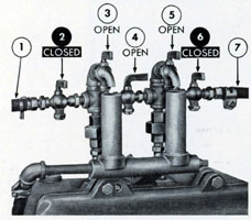
Figure 3-1. Valves and vent cocks in secured position.
3A2. Opening the sea valve. Raise the deck
plate above the sea valve. Turn the sea valve
handwheel in a counterclockwise direction as
far as possible to fully open the sea valve gate.
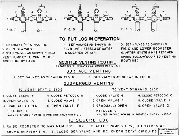
3A3. Venting the system. a. While submerged. When venting the underwater log
system while submerged, the instructions
given in Figure 3-3 should be followed. Improper venting procedure will crush the bellows mechanism or throw it out of calibration.
With other procedures than that described in
Figure 3-3, it is practically impossible to open
or close the dynamic and static pressure valves
simultaneously so as to keep the pressures
on both sides of the bellows equal. The
described procedure may also be used for
surface venting.
b. When surfaced. For best results the
system should be vented when the submarine
is stationary. The purpose of venting the hydraulic system is to remove any air that may
be trapped in the system. The following venting routine includes venting the pump. When
the ship is once underway it is not necessary,
to include the operation of venting the pump.
However, the rest of the venting routine that
applies to the valves located above the control
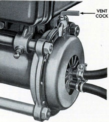
unit should be carried out daily. Vent the
pump by opening the vent cock located on the
pump until a clear stream of water, free of
spitting, is obtained; then close the pump vent
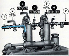
cock (Figure 3-5). Turn the valves located
above the control unit from their secured position as shown in Figure 3-1 to the venting
position as shown in Figure 3-2. Keep the
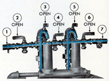
Figure 3-4. Valves and vent cocks in operating position.
valves in this position until a clear stream
of water, free of spitting is obtained; then
turn the valves to their operating position as
shown in Figure 3-4.
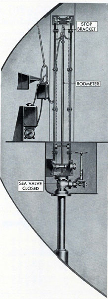
3A4. Lowering the rodmeter. The rodmeter
will be in one of two positions: the normal
housed position as shown in Figure 2-6, or
Figure 3-5. Pump vent cock.
Figure 3-6. Rodmeter in secured position
24
the fully housed position as shown in Figure
3-6. To lower the rodmeter, turn the hoist
crank counterclockwise until the rodmeter is
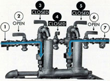
Figure 3-7. Valves and vent cocks operating on static head.
approximately 5 inches below its normal
housed position. Keep the rodmeter in this
position until the pump motor and pump are
operating; then lower the rodmeter to its
operating, or fully extended, position. Keep
the hoses clear of projections or chain links.
The rodmeter is in its operating position when
the clamp and guard assembly at the top of
the rodmeter is flush with the top of the sea
valve extension.
3A5. Securing the log. Whenever the ship
enters port, the log system is secured. Secure
the system in the following manner: Turn
the hoist crank in a clockwise direction until
the top of the rodmeter is level with the
marker plate, indicating that the tip of the
rod is clear of the hull. Keep the hose clear
of projections as the rodmeter is raised. The
rodmeter may be raised to its fully housed, or
secured, position, by turning the crank until
the top of the rodmeter hits the stop at the
top of the hoist. Turn the valves above the
control unit to their secured position as
shown in Figure 3-7. Turn the 1Y, 2Y, and
3Y switches on the I.C. board, and the conning
tower repeater switch on the A.C.O. board
to their OFF positions. Do not turn off the
switches until the log has stopped operating.