2A1. Hydraulic motors. The pressures required to operate the hydraulic equipment
are developed by electric motor-driven pumps.
Hydraulic motors, such as actuating cylinders,
are generally regarded as the power
units. Like other motors, they do not actually
create their own power. They merely convert
hydraulic power which has been built
up elsewhere into mechanical energy. Pumps,
therefore, act as the central power supply for
the entire hydraulic system by creating pressure in the system.
B. IMO PUMPS
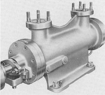
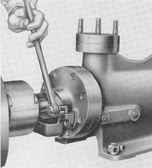
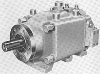
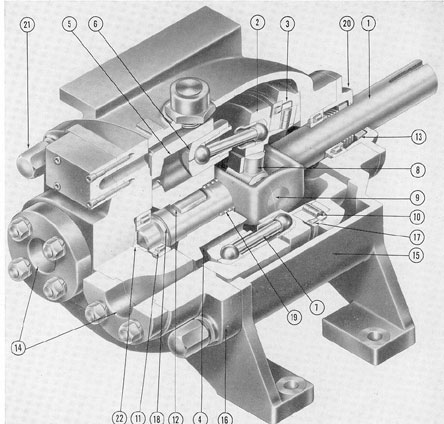
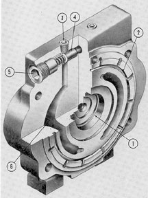
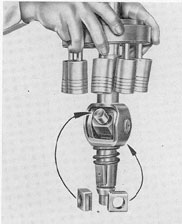
2B1. General description. The IMO pump
(see Figure 2-1) is a power-driven rotary
pump, consisting essentially of a cylindrical
casing, horizontally mounted, and containing
three threaded rotors which rotate inside a
close-fitting sleeve, drawing in oil at one end
of the sleeve and driving it out at the other.
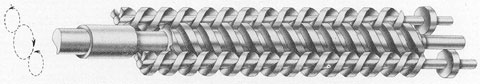
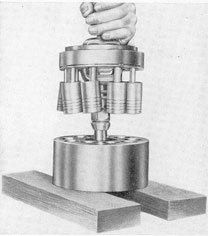
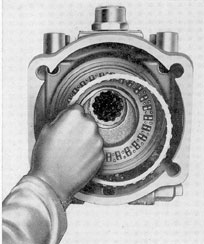
2B2. Detailed description. a. The rotors.
The rotors of the IMO pump, which resemble
worm gears, are shown in Figure 2-2. The inside
diameters of the spiral "threaded portions" of
the rotors are known as the troughs
of the thread; the outside diameters, or crests,
are known as the lands. The troughs and lands
of the adjacent rotors are so closely intermeshed that,
as they rotate, the meshing surfaces push the oil
ahead of them through
the sleeve, forming, in effect, a continuous
seal, so that only a negligible fraction of the
oil trapped between the lands can leak back
in the direction opposite to the flow.
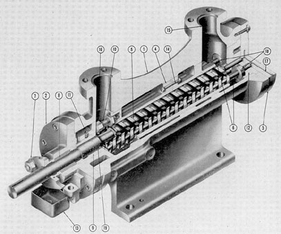
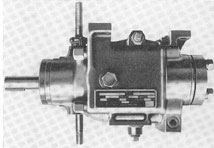
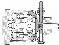
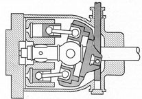
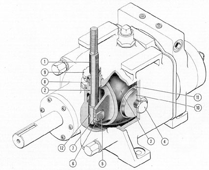
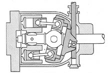
A cutaway view of the, pump is shown in
Figure 2-3. The center rotor, (5) is
Figure 2-1. IMO pump.
power-driven; its shaft is direct-coupled to an 18-horsepower
electric motor which drives it at
1750 revolutions per minute. The other two
rotors (6), known as idlers, are driven by the
center rotor which, through the intermeshing
of its threads with those of the idlers, communicates
the shaft power to the idlers and
forces them to rotate in a direction opposite
to that of the center rotor. The rotation of
the center rotor is clockwise as viewed from
the motor end of the coupling shaft, while the
rotation of the two idler rotors is counter-clockwise.
The end of the power rotor nearest the
motor rotates in the guide bushing (9); the
rotor shaft extends out through the end-plate,
where it couples to the shaft of the electric
motor which drives it. Leakage around the
shaft is prevented by five rings of 3/8-inch
Figure 2-2. IMO rotors.
17
square flexible metallic packing (8) which
is held in place by a packing gland (7). Any
oil which does leak through the packing falls
into the drip cup (13).
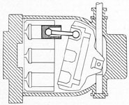
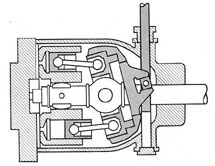
b. The sleeve. It should be emphasized
that the rotors are not housed directly within
the casing itself (1), but within a removable
two-piece sleeve (4) which fits snugly inside
the casing proper and can be quickly removed
and replaced as soon as it shows signs of wear.
The two pieces of which the sleeve consists
are bolted together near the center of the
casing, as shown, by the sleeve bolts (14). The
sleeve is secured against longitudinal drift
by the two adjusting bolts, one of which (10)
is shown in the cutaway. Rotary motion is
prevented by three taper pins (not shown in
the cutaway) which project into the sleeve
and bearing block from the casing.
The casing contains two ports, the suction
port (15), which receives oil from the
supply tank at a pressure of from 10 to 25
pounds per square inch, and the discharge
port (16) from which it is discharged into the
system.
c. Elimination of axial thrust; the balancing
connection. It must be remembered
that the function of a pump is merely to displace
fluid by mechanical action. This displacement will
of in itself create any pressure
throughout the fluid being pumped unless
the movement of the fluid encounters resistance
somewhere in the system beyond the
point at which it is discharged from the pump.
The working pressure of the main hydraulic
system, of which the two IMO pumps are the
power supply units, runs between 600 and 700
pounds per square inch. It is prevented from
exceeding this value by relief valves and an
automatic bypass, or unloading, valve (see
Chapter 1, page 15). But it will not reach
this working pressure, or in fact any pressure
above the 10- to 25-pound "back-pressure" at
which the oil enters the suction side of the
pump from the supply tank, unless the oil being
driven out of the discharge side of the
pump encounters a corresponding resistance
somewhere else in the system. In short, when
the hand bypass valve is open, the oil circulates
at no-load, that is, at the same pressure
as the pressure existing in the supply tank
or reservoir.
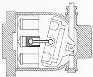
Since pressure existing anywhere in an
enclosed liquid is transmitted equally in all
direction's (see Chapter 1, page 5), it follows
that any pressure which the intermeshed rotors
have developed in the oil by the time it
reaches the discharge end of the sleeve will
be exerted against every surface with which
this oil is in contact, including the threads of
the rotors themselves. In other words, if the
full working pressure of from 600 to 700
pounds per square inch is developed at the
discharge port, a pressure equal to 600 to 700
pounds per square inch would necessarily be
exerted against the rotors in the direction
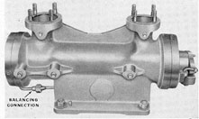
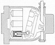
Figure 2-4. IMO pump showing pipe plugs and
balancing connection.
opposite to which the oil was being moved by
the rotors. This pressure would then express
itself as an axial, or longitudinal,
thrust tending to force the rotors against the bearing
block (12, Figure 2-3). This would naturally
result in excessively high friction, with consequent
rapid wear of all moving parts
involved. Therefore this axial thrust must be
equalized or balanced in some way.
To supply this balancing or equalizing
force, a small pipe, called the balancing
connection is provided. This connection permits
oil from the discharge end of the pump to
flow into the equalizing channel (17, Figure
2-3) in the end-plate at the suction side of the
pump. Figure 2-4 shows the balancing connection.
The cutaway, Figure 2-3, shows the equalizing
channel (17) in the end-plate. A study
of the cutaway will show that from the equalizing
channel, three lines open from the endplate into
the bearing block at the points
where the ends of the rotor shafts extend into
it. The function of this equalizing channel
is to allow the oil to bear against the ends of
the rotor shafts at the suction side of the
pump with the same pressure which it is exerting
against them at the discharge end. In
effect, the three rotors are floated between
equal oil pressures exerted against their opposite
ends, thus eliminating axial thrust.
The ends of the shafts of the idler rotors (6)
are fitted with collars (18) to locate the axial
position of the rotors. Another compensating
area for elimination of axial thrust against
the center rotor is seen at the bearing journal
(19), which forms a shoulder on the shaft just
at the point where the journal enters the
guide bushing.
The IMO pump is ideally adapted for
continuous, long-term service. It is quiet and
efficient in performance, requiring a minimum
of attention.
2B3. Operating instructions. Before an IMO
pump is started for the first time, the motor
wiring should be checked for proper rotation
as indicated by the arrow on the pump casing.
To start the pump, open the quick-throw valve
at the supply tank, and the-quick-throw valve
and hand bypass valve on the main supply
manifold. Then turn the motor switch to ON.
If the pump is unusually noisy when started,
it should be shut down immediately and the
system investigated for a clogged line, dirty
strainers, or a closed valve which prevents the
flow of hydraulic fluid.
19
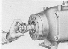
2B4. Maintenance. Once the pump is in service, it requires no attention other than an
occasional inspection for leakage at the packing gland. If, however, excessive leakage
occurs, the packing must be replaced.
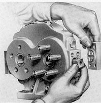
To replace packing, remove the two packing-gland
nuts as shown in Figure 2-5. Pull
out packing gland and remove the packing.
After new packing has been assembled,
the nuts should be tightened enough to seat
the metallic packing rings, and then backed
off and set up again without using a wrench.
Excessive gland pressure on the packing
causes scoring of the shaft as well as rapid
deterioration of the packing. Adjust the gland
nuts about finger tight. The final adjustment
should be made with the pump running.
Figure 2-5. Removing packing gland nut.
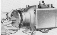
2B5. Disassembly and re-assembly. When it
becomes necessary to overhaul the IMO
pump, its disassembly is quite simple (see
Figure 2-3). Proceed as follows:
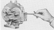
a. Removing taper pins. On one side of
the pump (see Figure 2-4), are three pipe
plugs. Each one holds in place one of the
taper pins mentioned in Section 2B2b, which
must be removed as the first step in disassembly.
These pins are individually fitted to
their holes to insure correct alignment of the
sleeve and bearing block. Before removal,
their positions should be marked with a prick-punch
so that they may be replaced in their
original holes.
b. Removing end-plates. Taking off the
two end-plates (2 and 3) then frees all of the
inner parts for removal.
c. Removing sleeve. The two halves of
the sleeve (4, Figure 2-3), which are shown
bolted together in the illustration, are fitted
together in a step joint. Mark the parts
with a prick-punch so that they may be
reassembled in their original arrangement. The
sleeve is maintained in its correct longitudinal
position within the casing by the adjusting
bolts (10). The settings of the adjusting
bolt should not be altered during disassembly.
d. Replacing guide bushing. When replacing
the guide bushing (9), be sure it is
firmly secured by the jam screw (11).
e. Renewing sleeve. When it is necessary
to renew the sleeve, the two halves of the
new sleeve must be carefully fitted so that
the inner and outer surfaces of the one half
line up with those of the other. They are
then bolted together and installed in the
pump, and aligned longitudinally by the
adjusting bolts. These should be so adjusted
that the shoulder on the discharge end of the
sleeve fits tightly against the counterbore at
that end of the casing. These adjusting bolts
are necessary to correct for individual differences in longitudinal dimensions resulting
from tolerances allowed in manufacture.
Also, the length of that portion of the
adjusting bolt which protrudes from the
tapped hole in the sleeve must be sufficient
to bear tightly against the inner face of the
end-plate. It must be tight enough to hold
the sleeve in position, but not sufficient to
prevent the end-plate from being bolted
solidly to the casing. In practice, the proper
adjustment of the adjusting bolt is determined
by taking a trial setting. First, bolt on
the end-plate, without the paper gasket; then
estimate the additional clearance needed between
the end-plate and the casing, allowing
for the thickness of the gasket; screwing in
the adjusting screws to the estimated
clearance around in the trial setting will then bring
the sleeve into longitudinal alignment.
20
C. THE WATERBURY SPEED GEAR
2C1. Introduction. The actuation of the
various hydraulically operated units on board
a submarine often requires great precision of
control, and transmission of power at variable
speeds and pressures, without any sharp steps
or gradations. The hydraulic machine used
for many of these operations is the Waterbury
speed gear, a quiet, efficient mechanism
which furnishes instant, positive, and accurate
hydraulic power transmission.
2C2. A-end pumps and B-end motors.The
Waterbury speed gear may be used either as
Figure 2-6. Waterbury A-end.
a pump (converting rotary mechanical motion
into hydraulic fluid displacement), or as a
hydraulic motor (converting hydraulic fluid
displacement into rotary mechanical motion).
The type of Waterbury speed gear generally used
as a pump is designated as a
Waterbury A-end speed gear (see Figure 2-6).
The type generally used as a hydraulic motor
is designated as a Waterbury B-end speed
gear, or Waterbury B-end hydraulic motor
(see Figure 2-7). In one special installation,
the A-end type is used as a hydraulic motor,
but since this is not generally the case, it will
be convenient to describe the A-end type
primarily as a hydraulic pump.
A-end and B-end speed gear are often
used together to form a pair of power
transmission
units, separated by any required
length of hydraulic piping to suit the needs
of a particular installation. So used, they receive
rotary mechanical motion from an electrical motor
at one point and transmit it as
a fluid displacement to any required point,
where it is reconverted into rotary motion,
with a positiveness and fineness of control
which could not be achieved by the use of
electric motors alone.
The size of the Waterbury A-end speed
gear, used in the submarine hydraulic system.
primarily as a pump, is designated as No. 5-A.
The sizes of B-end motors used are designated
as No. 5-B and No. 10-B.
Inasmuch as this chapter is devoted to
sources of hydraulic power, we shall here
Figure 2-7. Waterbury B-end.
concern ourselves primarily with the
Waterbury A-end speed gear in its use as a pump.
It will then be convenient to consider briefly
the operation of the Waterbury B-end speed
gear as a hydraulic motor; this will be readily
understood as a not very extensive departure
from these principles.
2C3. The Waterbury A-end pump. a. Use
of the Waterbury A-end pump in submarine
hydraulic systems. The Waterbury A-end.
pump is operated by a rotating shaft which
may be driven either by an electric motor or
by hand.
Three motor-driven and three hand-driven
Waterbury A-end pumps are used in
the submarine-one of each type in the
steering system, stern plane system, and bow
plane system. In operation by normal power,
the two types are used in each system as
team; the motor-driven unit transmits oil for
the power actuation of the system, while the
hand-driven unit fitted with a large handwheel
21
and designated as a telemotor, or telemotor
pump, transmits oil to a control cylinder to
provide fine control of the output of the
motor-driven unit. The hand-driven unit
is also used, alternatively, to operate the
system by hand whenever it is desired not to
use the motor-driven pump.
b. Operating principle. Although the
Waterbury A-end speed gear is actuated by
rotary motion, in principle it is actually a
reciprocating multiple-piston type of pump.
It consists of a casing containing three basic
elements:
Figure 2-8. Tilt-box at neutral.
Figure 2-9. Maximum tilt.
1. A socket ring, which in ball sockets
holds seven or nine piston connecting rods,
arranged roughly in circle around the driving
shaft as a center.
2. A cylinder barrel, in which are bored
the seven or nine corresponding cylinders.
3. A tilt-box, which alters the angle and
direction of the socket ring with respect to
the cylinder barrel.
The socket ring and cylinder barrel are
mounted on the drive shaft so that they rotate
together. The socket ring is so arranged that
it can be made to rotate either parallel to
the cylinder barrel or at an angle to it.
Connected to the tilt-box is a control shaft
extending through the pump casing. When the
control shaft is pushed up or down, it determines
the angle and direction of the tilt-box.
The diagrams, Figures 2-8 and 2-9, will
help to clarify the manner in which pumping
action is obtained. The socket ring rotates
within the tilt-box on the radial and axial
thrust bearings. As long as the tilt-box is
maintained in the vertical position, as shown
in Figure 2-8, the socket ring and cylinder
barrel will rotate parallel to each other, and
there will be no reciprocating motion of the
pistons within the cylinder barrel.
However, when the tilt-box is tilted in
either direction away from the vertical, as
in Figure 2-9, the socket ring no longer
rotates in the same plane as the cylinder
barrel. This means that as a ball socket on
the socket ring reaches that point in its
rotation which is closest to the barrel, the
piston belonging to it will be driven down
into the corresponding cylinder, and then,
as this same ball socket recedes to the point
farthest away from the barrel, the piston will
be withdrawn again.
Figures 2-10, 2-11, and 2-12 will help still
further to clarify this action. They show the
tilt-box tilted away from the vertical, and
illustrate the course of a single piston, whose
motion we are able to follow as the socket
ring turns through a half-cycle (180 degrees).
As the piston rises to its uppermost
position, as shown in Figure 2-10, it occupies
a progressively smaller space in the cylinder,
until it reaches the point at which the socket
ring and barrel are farthest apart. The partial
vacuum in the chamber, produced by the outward
movement of the piston, causes the fluid
to be forced into the cylinder.
In moving from its uppermost position
to its intermediate position, Figure 2-11, the
piston moves into the cylinder and begins to
displace the fluid accumulated there. At its
22
lowest point, Figure 2-12, the piston occupies
almost the entire cylinder. The expulsion of
the fluid through the discharge port is now
complete. The piston again rises from this
position for the suction stroke.
The repetition of these movements in
sequence by all of the pistons results in a
smooth, nonpulsating flow of hydraulic fluid.
Now that the pumping principle of the
Waterbury A-end speed gear has been illustrated
diagrammatically, we are ready to
consider in detail the parts of which it is
composed.
c. Basic differences between A-end and
B-end. For the sake of simplicity and clarity
of explanation, the mechanism of the speed
gear is illustrated, in Figure 2-13, by a cutaway
view of the B-end (hydraulic motor)
type. The B-end motor has been selected for
the cutaway view instead of the A-end pump
because the actual appearance of the tilt-box
and control shaft parts in such a view of the
A-end pump would appear too complicated.
Therefore, a word of explanation is needed
here as to the basic structural difference between
A-end and B-end speed gears.
In the A-end type, as already explained,
the angle between the socket ring and the
cylinder barrel-which determines the
amount of displacement caused by the pistons
in the cylinders as these elements rotate
is determined by a tilt-box whose angle is,
in turn, controlled by a control shaft. The
A-end is therefore said to have
variable displacement of the pistons.
In the B-end type, this tilt-box is replaced by
an angle-box (see Figure 2-14),
which may be loosely described as a "permanently
tilted tilt-box." This angle-box is
bolted solidly to the inside of the case, presenting its vertical side to the end of the case,
and its slanted face to the socket ring which
rotates against it. The important point is
that, unlike the tilt-box, it is immovable, so
that its direction and angle of tilt are fixed
and permanent. Therefore it does not need a
control shaft.
There is also a difference between the
spacing of the sockets in the socket ring, and
of the cylinders in the cylinder barrel, in the
two types of speed gear, of which a detailed
explanation is given in Section 2C4b.
Figure 2-10. Piston on top.
Figure 2-11. Piston in middle.
Figure 2-12. Piston of bottom.
However, the basic structural differences
between an A-end pump and B-end motor may
be summed up as follows:
1. The A-end has a variable tilt-box and
a control shaft.
2. The B-end has fixed angle-box and
no control shaft.
23
Once this structural difference between
A-end and B-end is clearly understood, the
cutaway view, Figure 2-13, which shows the
B-end with the angle-box can then be used
to illustrate our discussions of the A-end
pump with which it is identical in all other
details.
2C4. Detailed description of parts. a. The
case. The case, or casing (15, Figure 2-13),
is a light metal casting tested to a pressure
of 80 pounds per square inch and formed
roughly into a square, boxlike shell with an
opening at each end. As can be seen in Figure
2-13, the far end, in the view shown, is
considerably smaller than the near end.
The inside surface of the case is rough machined.
The larger end is finish-machined to take
the valve plate (16) which is held to the case
by four heavy studs, or tie-bolts, called the
case bolts (21). The case bolts extend all the
way through the case beyond the squared
shoulder near the smaller end, where spot-faced surfaces are provided to serve as seats
for the stud-ends.
The smaller end is finish-machined to
take the end-plate (20) which is screwed to
the case by six small Allen-head screws that
fit down into countersunk holes in the endplate
so that, when secured, they come down
flush with the plate. This end also contains a
finished surface to receive the main shaft
roller bearing.
In the center of the case, as viewed from
the top, is a tapped hole which receives a
fitting from a vent and replenishing line. A
similar tapped hole in the bottom of the case
serves as a drain. When the pump is mounted
bottom-side up, the functions of these two
holes are reversed.
Cast integral with the case are tie mounting
brackets. These have drilled and spot-faced
mounting holes.
The smaller end of the A-end pump also
has vertical holes drilled through the top and
bottom, 1 3/4 inches to the right of the center
line of the shaft as viewed from the shaft
end, machined and tapped to take the control
shaft bearing and guides (not shown in
Figure 2-13). Either the top or bottom hole
may be used to provide a passage for the
control shaft, depending on which way the
pump is mounted, and on other installation
limitations. Whichever hole is used for the
control shaft the opposite one is generally,
though not necessarily, used for the shaft
which operates a centering device mounted
over it. When the second hole is not used, it
is closed by a plug.
b. The main shaft. The main shaft (1,
Figure 2-13) is direct-coupled to the electric
driving motor. It is rotated clockwise as
viewed from the motor end of the shaft. The
function of this shaft is to drive the revolving
group of which it is a part. The revolving
group consists of the following units: shaft
(1), universal joint (8), cylinder barrel (4),
pistons (6), connecting rods (7), barrel spring
(19), socket ring (2), and barrel keys (12).
The main shaft rotates in two roller bearings,
one of which is contained in the smaller
end of the case itself, and the other in the
valve plate.
At the point where the shaft intersects
the socket ring, it forms a closed yoke to
which the universal joint (8, Figure 2-13) is
held by the shaft pin (9). The shaft is
flattened and perforated on two sides to provide
for the barrel keys (12) which drive the
barrel. A grooved section on the shaft
receives the barrel lock spring (18, Figure 2-13)
which serves only to prevent the barrel from
slipping off the shaft.
The correct amount of end-play for the
main shaft, amounting to 0.015 of an inch, is
insured by inserting a spacer in the bearing
recess of the valve plate beyond the shaft
bearing. The thickness of this disk is
determined after the rest of the parts have been
fitted to each other, so that it can compensate
for end-play error caused by tolerances in the
manufacture of the other parts.
c. The socket ring. The socket ring, (2,
Figure 2-13) contains the sockets into which
the large ball-ends of the connecting rods
are secured.
Four arms extend inward from the socket
ring body to form slots or pockets which
receive the bearing blocks. Allen-head screws
secure the bronze bearing blocks which support
the main shaft trunnions. The universal
joint consists of a shaft-trunnioned block
oscillating with the pin (9) in the yokes of
the main shaft. The trunnions of the trunnion
block operate on the bearing surfaces cut into
the main shaft yoke. The working torque of
the shaft is transmitted through the socket
ring, the universal joint trunnions, and the
main shaft pin. The back of the socket ring
is equipped with a roller track with two roller
faces. These become the outer races of the
axial thrust bearing (10) and radial thrust
bearing (17).
An examination of the socket ring will
disclose that the sockets are spaced unequally
around the main shaft. The reason for this
irregularity in the location of the sockets is
that when two parts connected by a universal
joint rotate in different planes-that is, on
different axes-their angular velocities
25
(number of degrees through which they turn in a
given length of time) are not equal throughout
all phases of a cycle.
In other words, if one of these parts is
driven at a constant speed of rotation, the
part which it drives through the universal
joint will alternately lag behind, and then
catch up with, the part which is driving it.
The mathematical or geometrical proof of
this fact is too complex to be given here. The
fact remains that this is exactly what happens
in the relationship between the rotational
speed of the main shaft of the Waterbury
speed gear and that of the socket ring which
it drives, whenever the tilt-box is tilted away
from vertical; the main shaft is driven by an
electric motor at constant speed, while the
socket ring, when tilted away from vertical,
alternately lags behind it and catches up,
during each full revolution of the shaft.
The greater the angle of tilt away from
vertical, the greater the inequality of motion
between the two parts during a given revolution.
If this irregularity were not corrected,
the delivery of fluid would rise and fall in
volume throughout each complete revolution,
resulting in uneven surges instead of smooth,
uninterrupted flow.
Therefore, in order to reduce this irregularity
in the pumping action of the pistons
to a minimum, they are spaced in such a way
that the inequalities in the distances between
them will just compensate for the inequalities
of motion between the shaft and the socket
ring. The cylinders, of course, are also unequally
spaced in the cylinder barrel to
correspond with the spacing of the sockets.
A little study will show that this compensation can be only approximate, for two
reasons, which result in two separate factors
of error:
1. The first factor of error results from
the fact that the amount of inequality of
motion between the two rotating parts varies
with the angle of tilt. At zero degrees' tilt,
the inequality is zero, as the two parts are
then rotating in the same plane. At maximum
tilt in either direction, the inequality is at
its maximum. And at any intermediate angle
between zero and maximum, the amount of
inequality is proportional to the degree of
tilt. Obviously the spacing or calibration, of
the socket, can be correct only for one particular
angle, and becomes less and less accurate
as the socket ring is tilted either way
from this angle. For the A-end speed gear
used in the submarine, the calibration angle
is 10 degrees (in either direction from
neutral).
Figure 2-14. Diagram of B-end.
2. The second factor of error results from
the fact that the inequality of motion between
the two rotating parts is continuous throughout any given cycle, or revolution, while the
location of the sockets, and of the cylinders
in the barrel, is discontinuous. Therefore it
would be impossible to make the calibration
exact-even neglecting the first factor of
error-unless the number of sockets and
cylinders was infinite, so that they formed a
continuous, irregular line around the
circumference of the socket ring and cylinder
barrel.
In this connection, there is a further
structural difference between the A-end and
B-end speed gears besides those already noted
in Section 2C3c. The sockets in the A-end are
located at unequal distances from each other,
but at the same distance from the centerline
of the shaft. The sockets in the B-end, however,
are located at unequal distances not
only from each other but also from the center.
In other words, the spacing of the A-end
sockets is unequal but concentric, while that
of the B-end sockets is not only unequal but
eccentric as well. The reason for the double
calibration is that the calibration of the B-end
must compensate not only for its own internal
mechanical inequality of motion, caused by
26
the action of the universal joint, but also for
the surges, or slightly unequal pumping, of
the A-end pump when this is its source of
hydraulic power. Therefore, in the
Figure 2-15. Separating shaft from barrel.
calibration of the B-end socket ring and cylinder
barrel, an attempt is made to correct two
errors at once:
1. The unequal spacing of the cylinders
from each other compensates for the internal
mechanical inequality motion arising from
the action of the universal joint in the B-end
motor itself.
2. The eccentricity or unequal spacing,
of the cylinders from the center, compensates
for the surge delivery of the A-end pump so
that the B-end shaft will turn at exactly the
same speed as does the A-end shaft when the
A-end tilt-box is at maximum tilt. The A-end
is calibrated for an angle of tilt 10 degrees
either side of neutral; the B-end is calibrated
for the full tilt of 20 degrees from vertical,
corresponding to the permanent tilt of its
angle-box.
d. The cylinder barrel. The cylinder
barrel is in reality a cylinder block into which
seven or nine separate cylinders are bored.
The length of the cylinders is such that the
pistons riding within each separate cylinder
will, as a group, always be within the cylinder
barrel (see Figure 2-15). As noted in the
description of the socket ring, the cylinders
are spaced unequally from each other to
compensate for the inequality of motion between
the socket ring and the main shaft arising
from the action of the universal joint. (For
a fuller description of this feature, see Section 2C4b).
The cylinder barrel has keyways cut into
it and is loosely attached to the main shaft
by two keys (12, Figure 2-13), so that end
play of the shaft will not be transmitted to
the barrel. The looseness of this attachment
of the cylinder barrel is intentional; its
purpose is to allow a slight play, permitting.
the pressure of the oil being pumped, or of
the spring, when the pump is not pumping,
to hold the barrel squarely against the valve
plate.
The spring, which is backed by the main
shaft yoke, maintains the barrel continuously
against the valve plate when the pump is not
running, or when the socket ring is in neutral.
When the unit is pumping, the oil under
pressure automatically maintains the barrel
against the valve plate, since the cylinder
ports are smaller than the cylinders of the
barrel, so that the pistons, forcing oil out of
the cylinder during the discharge stroke, will
also cause the oil to exert a force against the
walls formed by the ports, holding the barrel
tight against the valve plate.
e. Piston assembly. Each cylinder in the
cylinder barrel contains a piston which has
been ground and fitted in the cylinder, and
therefore requires no rings or packing.
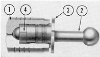
Figure 2-16 shows a cutaway view of a
single piston. The shallow grooves cut around
Figure 2-16. Cutaway of piston assembly.
1) Piston; 2) connecting rod; 3) cap nut; 4) socket
cap.
27
the piston interrupt the streams of oil leakage,
thereby tending to trap small particles
of dirt or grit which otherwise might score
the piston and cylinder surfaces.
Each piston (6, Figure 2-13) is connected
to the socket ring (2) by a connecting rod (7).
The rods have ball-ends, one larger than the
other. The large end is secured into the socket
ring, the small end into the piston.
1. Assembly of connecting rods to socket
ring. The connecting rods are secured in the
socket ring in the following manner. Into
the face of the socket ring are bored and
tapped seven or nine holes, one for each
piston rod. Each hole is then provided with
two hollow bronze half-bushings which, when
fitted to each other, form a spherical, cuplike
socket in which the large ball-end is held.
The inner half, called the ring socket, is
press-fitted into the bottom of the hole. The
outer half, called the socket cap, fits against
it, sliding into the hole with a rather free fit.
The socket cap is ring-shaped; its inside
diameter is sufficient to allow it to be slipped
over the small end of the connecting rod,
before that end has been secured into the
piston.
To lock the two halves solidly together
in the bottom of the hole, a threaded piece
shaped like a short section of pipe, called the
socket-cap nut, is then also slipped over the
small end of the rod and screwed down on top
of the socket cap.
In assembling the socket, the two halves
are not actually fitted directly to each other.
Instead, a thin metal ring, called a shim, or
spacer, whose function is to maintain proper
clearance for the contained ball-end, is inserted
between them, thus correcting any misfit resulting from tolerances in manufacture
of the different parts. Spacers for each assembly are individually selected to suit that
particular assembly.
The fit between ball and socket, when
assembled and locked in by the cap nut,
should be free enough to allow the connecting
rod, when standing upright, to fall over
sideways by its own weight. It must never be
loose enough to permit any axial motion, or
end-play, in the rod. If end-play exists, the
socket must be disassembled and the shim
replaced by a thinner one. If, on the other
hand, the fit is too tight, a thicker shim is
needed.
2. Assembly of connecting rods to pistons.
The manner in which the small ball-end of
the connecting rod is secured into the piston
is somewhat different from the manner of
securing the large end into the socket ring
(see Figure 2-16).
The piston itself (1) is of bronze, and the
inner half of the socket is hollowed out of
the metal of the piston.
Since the outer half, or socket cap (4),
must serve to hold the small ball-end in place
in the piston socket, it must necessarily have
a smaller inside diameter than the diameter
of the small ball. Therefore if it were formed
as a single piece, it could not be slipped on or
off the rod at all. Accordingly, it is made up
as a split bushing, that is, split into two equal
semicircular segments which are dropped into
the piston after the ball of the connecting rod
is placed in the inner hollow, or socket proper.
Then the piston is carefully tapped or shaken
until the two segments of the split bushing
fall into place around the rod. The piston
socket-cap nut (3) is flanged and slotted to
provide a wrench grip. Like the ring socket-cap
nut, it is threaded. After the split bushing
is in place, the nut is screwed down through
the tapped part of the piston interior to
secure the socket assembly firmly into the
bottom.
The fit between socket and ball should
be the same in the piston socket as in the ring
socket, that is, a free fit with no end-play. As
in the socket ring assembly, spacers or shims
of the required thickness are used between
the inner edge of the split bushing and the
shoulder cut in the piston against which they
fit to form the socket cup.
As can be seen in Figure 2-16, a small
hole is drilled through the crown of the
piston. This furnishes passage to the oil for
lubrication of the surfaces of the ball and
socket. Another hole (not visible in the
figure) is drilled lengthwise through
the connecting rod, ending at the tip of each ball.
28
Thus both sockets are provided with continuous
high pressure lubrication whenever
the pump is running. The oil, thus pumped
from the external, or high pressure, side of
the piston, leaks into the case, or inactive
system, and is a part of the oil loss which
must be constantly fed back into the active
system through the replenishing valves.
f. The valve plate. The valve plate (16,
Figure 2-13) serves as an end-plate, or cover
plate, for one end of the speed gear. Into it
are cast the oil passages which empty into the
suction and discharge ports (14, Figure 2-13).
It also holds the outer race of the roller
bearing (11, Figure 2-13) in which the end of the
main shaft revolves.
Figure 2-17 shows the inner face of the
valve plate against which the cylinder barrel
rotates. Oil is drawn into or discharged from
the cylinder through crescent-shaped
Figure 2-17. Cutaway of valve plate.
1) Main shaft bearing; 2) collector channel; 3) air
vent; 4) replenishing valve; 5) replenishing valve retainer plug; 6) port.
channels (6) cast in the inner face of the valve
plate. These communicate directly with the
passage leading to the external ports on the
valve plate's outer side. The two channels
are divided at the top and bottom by flat faces
called lands.
As the cylinder barrel rotates, the cylinders
pass in succession across these lands.
For a brief moment, fluid is locked in each
cylinder as it crosses the land.
The valve plate also contains two
replenishing valves and four vent valves, which are
described in Section 2C4h.
g. The tilt-box and the control shaft. The
tilt-box provides the roller tracks against
which the socket ring rotates, or, to put it
another way, it provides the opposite races
for the radial and axial thrust bearings
described in Section 2C4c.
The socket ring may be tilted to any
desired angle of tilt from 0 degrees to 20
degrees in either direction. This is
accomplished by a tilt-box (3, Figure 2-18), which
is suspended on two trunnions (10) formed
on the box itself and which ride in bronze
bearings (11) located in the sides of the case.
An elongated hole is cut through the center
of the tilt-box to give free passage to the
main shaft at any degree of tilt of the tilt-box.
The tilt-box is retained in its bearings
by two retaining trunnions (4, Figure 2-18)
which are screwed through from the outer
sides of the case and enter bushed holes in
the tilt-box.
The angle of the tilt-box is determined
by the control shaft (1, Figure 2-18) which
tilts the tilt-box on its trunnions to obtain
the desired amount of pumped fluid and to
control the direction of pumping.
The end of the control shaft which protrudes
from the case is threaded. This end
is connected to a control device either to
the linkage of a control cylinder assembly (if
it is functioning as a motor-driven pump), or
to a pump-stroke setting lever (if it is
functioning as a telemotor pump).
The control shaft fits into the case of the
speed gear through the control shaft bearing
29
(2). External oil leakage is prevented by the
packing (8), held in place by the packing gland cap (9).
The control trunnion pin (5) is secured
to the control shaft, inside the pump case, by
a dowel pin (12) which is peened over at both
ends. The control trunnion pin is fitted with
a pair of small square blocks, the outer guide
block (6) and the inner guide block (7); one
of these pairs can be seen in the illustration.
The vertical chamber in which the control shaft
moves is drilled cylindrically, and
then fitted with guides, or tracks, whose inner
surfaces are cut into rectangular channels,
thus giving the chamber a rectangular shape.
The outer guide blocks are held within these
rectangular vertical tracks, with which they
make a smooth, sliding fit. The inner and
outer guide blocks are free to move
independently, having no connection with each
other, except that they are both carried on
the trunnion pin, riding with it as it moves
up and down with the control shaft.
The fingers of the tilt-box (3) form a
pair of square recesses within which the
inner guide blocks (7) are held with a fit just
tight enough to allow the block to be tapped
into the recess by hand. This inner block is
also free to turn smoothly on the trunnion
pin. Therefore, as the control shaft is moved
by the external linkage, the inner guide
blocks, carrying with them the fingers of the
tilt-box, will cause the tilt-box to rotate on
its trunnions. Thus, the control shaft is fitted
to the tilt-box through the inner blocks, and,
as the shaft is moved by the external linkage
to any given position, the tilt-box will assume
a corresponding angle of tilt to follow it,
Figure 2-18. Cutaway of control shaft.
1) Control shaft; 2) control shaft bearing; 3) tilt-box; 4) tilt-box retaining trunnion; 5) control trunnion pin;
6) control guide block (outer); 7) control guide block (inner); 8) packing; 9) packing-gland cup; 10) trunnion; 11) trunnion bearing; 12) dowel pin for control trunnion pin.
30
within the limits of its angular rotation (20
degrees from vertical in each direction).
h. Minor parts. Any oil which has been
lost from the active, or pressure, side of the
system by leakage, is replenished in the
active, or pressure, side from the case through
two check valves, called replenishing valves
(4, Figure 2-17) which are located in the
valve plate. There is one for each port. The
replenishing valves allow replenishment of
oil from the case to the active, or pressure,
side of the system on the suction side of the
pump. When this side of the pump is the discharge side, the check valve will be seated by
the oil pressure, thereby preventing oil from
escaping from the active, or pressure, side
of the system back to the case.
The hole in the valve plate through which
the valve is inserted is kept closed by a plug
known as the replenishing valve retainer plug
(5). Above each port is a needle valve (3, Figure 2-17) which provides the means for venting air out of the valve plate. Two additional
needle valves are placed in corresponding
positions at the underside of the ports, to be
used as vents when the pump is mounted
upside down.
At the point where the shaft passes
through the case, oil leakage is prevented by
an oil seal (13, Figure 2-13). The seal is made
of a synthetic rubber ring protected by metal
guards. (A steel ring, with a ground surface,
is fitted into the metal guards which rotate
directly against a ground surface on the
pump end-plate.) The entire assembly of the
oil seal rotates with the shaft.
2C5. Operation of the Waterbury A-end
speed gear. a. As a motor-driven pump.
Three motor-driven A-end speed gears are
used in the submarine to furnish normal
hydraulic power, one for the steering system,
one for the stern plane tilting system, and
one for the bow plane tilting system. Each
speed gear is driven by an electric motor at
440 revolutions per minute. The motor used
to drive the speed gear on the steering system
is rated at 15 horsepower; the motors used
for driving the speed gears in the bow and
stern plane systems are rated at 7.1 horsepower each.
The shaft of the motor is direct-coupled
to the main shaft of the A-end pump, driving
it clockwise as viewed from the motor end
of the pump. Since the direction and speed
of rotation are fixed, the only variable factor
in determining how much oil is pumped by
the pistons, and in which direction it will be
pumped, is determined by the positions of the
tilt-box.
As this is one of the motor-driven pump
installations, the control shaft, which
determines the position of the tilt-box, is itself
controlled, through bell-crank linkage, by the
action of a control cylinder plunger.
Figures 2-19, 2-20, 2-21, and 2-22 illustrate
the relationship between angle of tilt and
pumping action. In Figure 2-19, the control
shaft is centered, the tilt-box is at neutral,
the socket ring is parallel to the cylinder
barrel, and no pumping action will occur since
each piston occupies the same amount of space
in its cylinder throughout each cycle, or
revolution. There is no suction and no
Figure 2-19. Tilt-box at neutral.
Figure 2-20. Tilt-box at slight tilt.
31
displacement. Note the position of the control shaft
and inner guide block.
In Figure 2-20, the control shaft has been
pushed down a short distance, tilting the
tilt-box slightly away from vertical, inclining the
upper part away from the cylinder barrel.
Figure 2-21. Tilt-box at maximum tilt.
Figure 2-22. Tilt-box at reverse tilt.
Since the socket ring is now rotating in a
different plane from that of the cylinder
barrel, each piston will acquire a reciprocating
motion, moving back and forth within its
cylinder during each full revolution, as it
alternately approaches and withdraws from
the cylinder barrel. Therefore, as they rotate,
each piston will alternately draw oil into its
cylinder during that half of the revolution
in which it is approaching the topmost position, and drive it out of the cylinder again
during the other half of the revolution during
which it is approaching the lowest position.
Each of the seven or nine pistons, in
turn, repeats this process during each revolution.
The volume of oil pumped will be relatively small, as the socket ring is tilted only
slightly from the vertical, and, consequently,
the displacement within the cylinders is
small.
In Figure 2-21, the control shaft has been
pushed down to its maximum travel, tilting
the tilt-box to its maximum angle of tilt, still
in the same direction away from vertical as
in Figure 2-20. The plane of rotation of the
socket ring now makes an angle of 20 degrees
with the plane of rotation of the cylinder
barrel. The piston displacement inside the
cylinders is at maximum, resulting in an
increased amount of oil being pumped, in the
same direction as in the preceding figure.
In Figure 2-22, the control shaft has been
raised to its maximum travel, again tilting the
tilt-box and socket ring to a maximum angle
of 20 degrees' tilt away from the vertical, but
in the opposite direction. Again there is
maximum piston displacement, but since the
direction of rotation is unchanged, the flow
of oil through the pump is reversed.
Since the control shaft can tilt the tilt-box to any desired angle of tilt within the
20-degree range on either side of neutral, it
is evident that the number of gradations in
the quantity of oil pumped from zero to
maximum is infinite. This factor makes possible
the fineness of control which is an outstanding
advantage of these pumps.
It should be made clear that, when the
A-end pump is pumping the maximum quantity
of oil, it is not necessarily delivering it
at maximum pressure. The reason for this is
that the farther the socket ring is tilted away
from the vertical and the greater the consequent piston displacement, the greater the
quantity of oil pumped in a given length of
time; on the other hand, the smaller the angle
of tilt, and consequent piston displacement, the
greater will be the mechanical advantage of
leverage exerted against the oil being pumped.
Therefore, if the angle of tilt is small, and the
resistance encountered by the oil is sufficient
to act as an effective obstacle to its flow,
enormous pressure will be developed.
b. As a hand-driven telemotor pump. The
output of the motor-driven Waterbury A-end
pump is controlled by a hand-driven telemotor
A-end pump. Three basic differences should
32
be noted between the operation of the motor-driven A-end pump and of the hand-driven
telemotor A-end pump:
1. In the motor-driven A-end pump, the
direction of rotation of the main shaft is
fixed, while in the telemotor pump, the shaft
may be rotated in either direction by the attached
handwheel.
2. In the motor-driven A-end pump, the
direction of tilt, as well as the angle of tilt
of the tilt-box, are variable; in other words, it
may be tilted up to 20 degrees in either direction away from the vertical.
3. In the motor-driven A-end pump, therefore, the direction in which fluid is pumped will
be determined only by the direction in which
the tilt-box is tilted. In the telemotor pump,
the direction in which fluid is pumped will be
determined only by the direction in which the
main shaft is rotated.
Though the tilt-box in the telemotor
pump can be tilted in only one direction, the
angle of this tilt is variable, and may be set at
anything from minimum to maximum. In
the case of the telemotor pump, this angle is
controlled by a pump-stroke setting lever, or
pump control lever, which is placed by hand
at any desired setting.
2C6. The Waterbury. B-end motor. a. Summary of structural differences. The basic
differences in structure between the A-end
pump and B-end motor have already been
discussed (see Section 2C3c). They may be
summarized as follows:
1. The A-end speed gear has a variable
displacement feature consisting of a tilt-box
whose position is determined by the vertical
control shaft. In the B-end speed gear, this
tilt-box is replaced by the angle-box, a casting
secured to the inside of the case, which gives
to the socket ring a fixed tilt of 20 degrees in
one direction from the perpendicular (see
Figure 2-14). The B-end motor has no control
shaft.
2. Both the A-end and B-end speed gears
have the sockets spaced at unequal distances
from each other in the socket ring. In the B-end, however, the sockets are also placed at
unequal distances from the center of the
socket ring; in other words, in the A-end the
sockets are unequally spaced but are concentric,
while in the B-end, they are unequally
spaced and eccentric.
2C7. Operation of the Waterbury B-end
speed gear. a. Use of the Waterbury B-end
speed gear in submarine hydraulic systems.
The A-end speed gear is used primarily as a
pump, converting mechanical torque into
hydraulic fluid displacement, while the B-end
speed gear is usually used as a hydraulic motor,
converting hydraulic fluid displacement
into mechanical torque. In practice, only two
B-end motor installations are used on the submarine:
1. A No. 10-B motor is used on all late
classes of submarines, both of Portsmouth design
and Electric Boat Company design, for
operating the rigging gear of the bow diving
planes, forward capstan, and anchor windlass.
The hydraulic power to operate this installation
comes from the main hydraulic system.
The shaft of the No. 10-B motor, through a
clutch and a series of gear trains, operates
the bow plane rigging gear, forward capstan,
and anchor windlass. This No. 10-B motor
will be replaced by a No. 10-A unit to decrease
the rigging-out time for the bow planes, since
the A-end, by maintaining a small angle of
tilt on the tilt-box, can rotate faster with a
given amount of oil from the main system,
assuming that the external loading is not excessive.
2. In some earlier classes of boats, a No.
5-B motor was used for the tilting of the bow
diving planes. In this type of installation, the
source of hydraulic power was a No. 5 A-end
pump driven by an electric motor; fluid under
pressure was delivered to the No. 5-B motor,
whose shaft, through a gear train, rotated a
large herringbone sector gear fixed to the
tiller of the plane stocks.
b. Principles of operation of the B-end
motor. When the Waterbury B-end speed
gear is used as a hydraulic motor, the principles of its operation are the reverse of those
of the Waterbury A-end pump. Instead of
torque being applied to the main shaft from
some external source to force the piston to
displace oil, and thereby develop fluid
33
pressure, here the fluid pressure is admitted to
the cylinders in order to force them to
reciprocate and rotate the shaft, developing in
the shaft a torque which is then used to
actuate some mechanism.
This will be made clearer by referring
again to the diagram, Figure 2-14. The oil
under pressure enters the channel in the valve
plate. From the channel it flows into all the
cylinders on that side whose ports are open to
that channel. This oil will tend to push the
pistons on this side of the cylinder barrel out
of their cylinders, exerting a force against
the socket ring. The socket ring, fitting
squarely against the axial roller bearing of
the angle-box, which is at an angle and is free
to turn, will thereby receive the force exerted
on it by the pistons and their connecting rods
and convert it into rotary motion. The socket
ring will therefore rotate against the inclined
plane of the angle-box, transmitting its motion through the universal joint to the shaft.
Thus, the impulses received by the pistons
through the channel on the pressure side of
the valve plate tend to apply a torque to the
entire revolving group, consisting of the cylinder barrel, socket ring, and shaft.
As each cylinder in the cylinder barrel
is carried around toward its topmost position
(see Figure 2-14), the space in that cylinder
continues to increase as the oil under pressure
forces the piston farther out of the
cylinder, to its maximum intake stroke. At
this moment, the port of this cylinder is passing across the land on the valve plate, between
the two crescent-shaped channels, and the oil
in the cylinder remains trapped in it as long
as the cylinder port remains in contact with
the land.
As this cylinder begins its descent on the
other side of the motor, its piston, whose
socket in the socket ring is now riding down
the other side of the inclined plane on the
angle-box, is once again pushed down into the
cylinder, expelling the trapped oil through
the cylinder port into the opposite crescent-shaped channel. Consequently, the space within the cylinder continues to decrease during
this half of the cycle until it once again
reaches its lowest position, where again the
port of this cylinder is passing across
the opposite land of the valve plate, at which time
its piston has reached its maximum discharge
stroke.
If the oil under pressure, called pressure
oil, is continuously delivered to the side of
the motor, each piston in turn, as it receives
the impact of the oil against it, will go
through this cycle, receiving oil from one
channel on the ascending half of its cycle and
discharging it through the other on the descending half of its cycle, transmitting to the
socket ring, and thus to the shaft, a smooth,
virtually nonpulsating torque which, as long
as the shaft is free to turn, will be translated
into continuous rotation in one direction.
The port on that side of the motor which
receives pressure oil from the outside line is
termed the supply port; the other port,
through which the oil is expelled when the
pistons have completed their discharge stroke,
becomes the return port.
Since the direction of tilt of the angle-box is fixed, the direction in which torque is
applied to the shaft will be determined by
which port the motor receives the pressure
oil. In other words, if oil were delivered under
pressure to the opposite port, in the example
we have just considered, all the movement
described would be reversed. The pistons
would push the socket ring in the opposite
direction, and as a result, the shaft would turn
in the opposite direction.
In other words, since the direction of tilt
of the angle-box is fixed, it is clear that the
direction in which the shaft of a B-end motor
rotates is determined exclusively by the direction in which fluid is pumped to it. And
since the angle of tilt is fixed, it is clear that
the speed with which the pistons are pushed
out of their cylinders by the pressure oil, and
the consequent speed of shaft rotation, will
depend exclusively on the quantity of oil delivered to the motor in a given length of time.
If the shaft were free to turn, and carrying no load, it is clear that to keep it turning
just enough force would be needed at the
supply port to overcome the inertia and internal friction of the moving parts. However,
when a load is applied to the shaft, an
34
additional force proportional to the load must be
exerted against the pistons on the pressure
side of the motor. Since the piston area remains constant, this increase of force can be
made available only by an increase in the pressure of the oil delivered to the motor. Therefore, it is obvious that the amount of torque
available at the shaft will depend exclusively
on the amount of pressure, in pounds per
square inch, of the oil being delivered to the
motor.
The operational principles of a B-end
motor may now be summarized as follows:
1. The function of the B-end motor is to
receive hydraulic power from an outside
source in the form of continuous fluid displacement and convert it into a rotary motion
of its shaft.
2. The direction in which its shaft rotates is determined by which of its two ports
receives the supply of pressure oil.
3. The speed of rotation of its shaft depends on the quantity of pressure oil delivered to it per unit of time.
4. The amount of working torque available at its shaft is determined by the amount
of hydraulic pressure available at its supply
port. In practice, the normal working pressure
of the oil from the main hydraulic system received at the supply port of the No. 10 B-end
motor to operate the bow plane rigging gear,
windlass, and capstan runs between 600 and
700 pounds per square inch.
2C8. Service instructions. a. Air in the
system. Air in the hydraulic system hinders
its efficient operation, and great care must be
taken to prevent the entrance of air into the
lines, and to get rid of any air which may
have accumulated there. This applies also to
the Waterbury speed gear, whose case must be
kept filled with oil and free of air bubbles. To
vent off any accumulated air in the valve
plate, open the two air vent valves (3, Figure
2-17) on top of the valve plate. Turn the shaft
over a few times while the vent valves are
still open, to relieve any air which may be
trapped in the oil. Despite these precautions,
there may still be air in the system. The
Waterbury speed gear should be run for a
few minutes without load and with the vent
valves closed, then stopped and the vents
again opened as before until all air is removed. The hydraulic system should be
vented periodically until all air has been removed.
NOTE. The presence of air in the
hydraulic system may be detected by noisy
operation and by speed variations in the B-end, especially slowing down under load.
b. Handling controls. The life of the
Waterbury speed gear can be materially prolonged by observing proper precautions.
Avoid unnecessary sustained overloads. Even
though the gear is protected by relief valves,
it is well to slow down when excessive pressure is indicated or when obvious shocks are
expected. For example, when securing an anchor, the windlass should be operated slowly
during the last few feet of chain travel. Do
not keep the A-end operating unnecessarily.
c. Opening for inspection. As long as the
equipment operates satisfactorily, it should
not be opened. The units give the best service
when they are not disturbed.
2C9. Overhaul. Waterbury speed gears are
carefully assembled machines. Therefore,
when repairs are necessary, it is always best
to return them to a tender or base where
trained personnel and special tools are available. Unexpected circumstances, however,
sometimes make it necessary to restore the
units to immediate service, regardless of
whether the repairs may endure.
The following overhaul procedure is intended for such an emergency. It describes
primarily the B-end with variations for the
A-end procedure.
a. Disassembly. 1. Removing the oil.
Close all cut-out valves on the piping connected to the pump. Remove the drain plug
on the bottom of the case and drain the oil.
Disconnect the piping from the unit. Remove
pump from mounting.
2. Removing valve plate. Remove the
nuts and the bolts which attach the valve plate
to the ease. Tap the end of the shaft to free
the valve plate from the case. Take off the
valve plate, being careful not to bring the
3. Removing valves from valve plate.
The block containing the valves is mounted
on the side of the valve plate. Remove the
four bolts as in Figure 2-23. In some installations there is only a plug to be removed. Take
off the cover, and the replenishing valve parts
can then be removed as in Figure 2-24.
4. Removing oil seal. To do this, remove
the six bolts around the circular cover plate.
Remove the cover plate, and the oil seal elements can then be pulled out (see Figure
2-25).
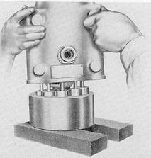
5. Separating case from rotating group.
Rest the open end of the case, through which
the cylinder barrel is visible on a pair of
wooden blocks. Remove the angle-box screws
from the end of the case. Lift the case straight
Figure 2-24. Taking out replenishing valve.
Figure 2-25. Taking off end cover.
up as in Figure 2-26. The angle-box should
remain with the revolving group. If it does
not, reinsert two of the angle-box screws part
way and loosen by tapping lightly. On the A-end, the revolving group is removed without
its tilt-box. The tilt-box may be freed by removing the trunnion retainers on the side of
the case. With the control in its neutral position, lift the tilt-box straight out from its
bearings.
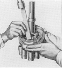
6. Removing shaft from barrel. The end
of the shaft beyond the barrel contains the
inner race for the valve plate roller bearing
(11, Figure 2-13). This must be taken off with
a bearing puller which is furnished as a
special repair tool. Pry off the barrel lock
ring with a screwdriver. Rest the barrel on
Figure 2-26. Lifting case.
36
the two wood blocks mentioned earlier. Lift
up the shaft, socket ring assembly, and pistons
as in Figure 2-15, being careful not to mar the
surfaces of the pistons.
7. Separating socket ring from shaft. Remove the screws which hold the bronze trunnion shaft bearing blocks in the socket ring
as in Figure 2-27. With the socket ring carefully held, drive the bearing blocks out by
tapping gently with a wooden drift. Figure
2-28 shows this operation. Push the shaft
through the socket ring as in Figure 2-29.
8. Separating piston assembly from
socket ring. It is seldom necessary to dismantle the entire socket ring assembly. Disassemble only the pistons which require
obvious repairs. Since the parts of each group,
such as pistons, rods, caps, and trunnion
blocks are hand-fitted at original assembly,
care should be taken to reassemble them so
that individual parts are returned to their
original location. Corresponding fitted parts
are usually numbered or punched as a relocation guide. For example, ring socket caps
and nuts are numbered to correspond with
hole numbers in the socket ring. If the parts
are not marked, they should be marked by
numbers or punch marks as they are removed.
The slot on the cap nuts and the corresponding locking hole on the socket ring are
prick punched for identification. Connecting rods
are not marked and should be tagged with the
numbers corresponding to their pistons.
Remove lock springs or split pins. Loosen
the cap nuts which secure the ball-ends of the
connecting rods (2, Figure 2-16) in the socket
ring. Pull the caps and rods out of the socket
ring, being careful not to wedge the edges
of the caps into the threads of the socket ring.
Figure 2-29. Separating shaft from socket ring.
37
Use a wooden clamp to prevent injury to a
piston when separating it from a rod. Make
the clamp by boring a hole of the same diameter
as the piston. Split the wood at the center
of the hole. Place the piston between the two
jaws just formed, in a vise. The piston should
be clamped at its solid end only, to avoid
crushing the hollow part. Unscrew the piston
cap nut (3). Pull the connecting rod (2) out
with the two halves of the split bushing (4).
Keep the two together for reinstallation in
the same piston (1).
9. Removing shaft trunnion block. Drive
the main shaft pin retainer out of the trunnioned
block. Drive the main shaft pin out of
the block and shaft. If it should be necessary
to replace the main shaft pin bushings, it can
be done by driving the main shaft pin bushing
out of the shaft.
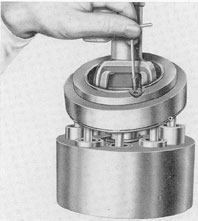
10. Overhauling radial and thrust roller
bearings. The thrust and radial bearings fit
loosely into the angle-box or tilt-box, which
ever the case may be, and may be lifted out
as illustrated in Figure 2-30. If any of the
rollers shows a defect, it should be removed.
This can be accomplished by removing the
rivets that hold the parts of the cage together.
A cage may be assembled with three or four
rollers missing, provided no two adjacent
Figure 2-30. Removing bearings.
boxes are left empty. This is suggested only
as an emergency repair. If spare bearings are
available, they should be used.
The socket thrust race is secured to the
socket ring by a shrink fit. It may be removed
by driving it off with a pin inserted into the
driving holes in the socket ring. This race is
reversible. When its bearing surfaces become
worn, it can be turned over.
The box thrust race fits snugly in either
the tilt-box or angle-box and can be lifted out.
This race is also reversible and can be turned
over if one side is worn.
The radial race is attached by a tap fit
and should be removed from the box by gently
jacking it out with a hook-shaped bar.
Reassembly of the thrust race to the
socket ring requires a shrink fit. It will
therefore be necessary to heat the race in an oil
bath to a temperature of about 270 degrees
Fahrenheit.
b. Reassembly. 1. Fitting connecting
rods to socket ring. If replacement parts are
used in the socket ring assembly, it will first
be necessary to fit the connecting rods into
the sockets. Assemble and tighten the cap nut
until the rod is held firmly in the socket, just
tight enough to allow it to be moved backward and forward and from side to side without difficulty. Repeat this motion several
times until a bearing surface is established.
This surface should be a band about 1/32-inch
in width around the ring socket and socket
cap.
When a satisfactory bearing surface has
been obtained, the fitting for proper freedom
of movement without end-play should be
made in the following way. Assemble connecting rods in the ring sockets with the ring
socket caps and cap nuts. The rod should fit
freely but without perceptible end-play. If
the fit is so loose that the connecting rod
shakes endwise after the nut has been tightened, it is necessary to dress down the end of
the socket cap slightly to obtain a tighter fit.
When dressing down the cap, draw it carefully over a fine file or emery cloth, and be
sure to check the end for squareness.
If, however, the rod fits too tightly, place
a shim between the socket cap and the socket.
38
To complete the installation of the replacement rod,
mark the lock hole location in the
lock groove of the socket ring with a prick-punch.
Carefully align the marks so that the
resulting hole will line up with a notch in the
cap nut. Drill a hole which will come through
the center of the notch. The nut must be kept
from turning during the drilling operation.
Remove burrs.
After all the replacement rods have been
fitted into the sockets, disconnect them for
further reassembly later. Each rod must be
tagged for proper relocation.
2. Fitting connecting rods to pistons.
The method of fitting the connecting rods
in the pistons differs somewhat from that of
fitting them in the socket because of the split
bushing. The following procedure is recommended for the rod and piston adjustments
where there is a split socket cap (4, Figure
2-16) which must be seated firmly against the
socket of the piston in addition to bearing
properly on the ball-end of the connecting
rod. If possible, secure a set of circular laminated shims. If this is not possible, prepare a
set of circular shims in thicknesses ranging
from 0.001-inch to 0.020-inch which will fit
between the piston socket cap (3, Figure 2-16)
and its seat in the piston. Laminated or prepared shims should be of smooth, flat brass and
without burrs. Place shims 0.015-inch thick in
the piston and reassemble the rod, cap, and
nut, screwing the nut down tight. Check the
rod for end-play. If it is too tight, select a
thicker shim. When the end-play has become
imperceptible, lock the piston cap nuts in
place. Reassemble the pistons and connecting
rods in the socket ring and insert the pistons
in their respective cylinders in the cylinder
barrel.
3. Reassembling shaft and socket ring.
Press the main shaft bushings, into the holes
in the shaft yoke and secure them with the
bushing pins. With the shaft trunnion block
in the yoke, press the main shaft pin (9,
Figure 2-13) through the block, passing it
through the bushings in the yoke, and secure
it in the block with the shaft pin retainer.
Place the trunnion bearing blocks on the trunnions
of the shaft pin and pass the shaft
through the socket ring, observing that the
socket which is radially in line with the trunnion
bearing block is in line with the shaft
keyway. Secure the blocks with screws.
4. Reassembling shaft, barrel, and socket
ring. Place the barrel spring (19, Figure
2-13) and keys (12, Figure 2-13) on the shaft.
The barrel key marked "V" is to be in line
with the keyway at the end of the shaft. Stand
the shaft on end with the socket ring down.
Keep it in that position in a properly padded
vise. Lower the cylinder barrel (4, Figure
2-13) with its pistons over the shaft and keys
so as to bring the corresponding connecting
rods and their sockets in the socket ring together.
In this operation, the pistons must
be retained in their cylinders to prevent their
sliding out of the barrel.
NOTE. The barrel must slide freely over
the keys. The barrel lock ring is then slipped
over the end of the shaft and snapped into the
shaft groove. Assemble the connecting rod
ends into the sockets of the socket ring with
the ring socket caps and cap nuts. Screw the
nuts down to the locking position as determined by the earlier fitting process. Insert
cotter pins into the nuts. Press the inner race
of the valve plate roller bearing (11, Figure
2-13) on the end of the shaft. The revolving
group is now ready for assembly with the
case.
5. Assembling B-end shaft group and
angle-box to case. Carefully place the revolving group on a flat surface with the barrel
down. Place the rollers in position on the rotating group. Place the angle-box and races
on top of the rollers. Work the box back and
forth until it is properly seated.
Press the angle-box dowels into place in
the case. Lower the case over the revolving
group so that the dowels slip into the holes
in the angle-box and the box seats in the recess of the case.
6. Assembling A-end control shaft and
tilt-box. If the parts of the control have been
disassembled, restore them in the control
housing. Replace the washer and screw the
control shaft bearing (2, Figure 2-18) down
tight. Insert the packing (8, Figure 2-18) and
the gland and secure it with the gland cap
39
(9, Figure 2-18). Prepare the tilt-box for installation by pressing down the radial race.
Insert the thrust race and put the rollers in
place. Press the retaining trunnion bushings
into their sockets in the tilt-box. For the installation, set the case open-end up. Place the
case trunnion bushings which are half segments, in the openings in the sides of the case
so that the tilt-box forks engage the outer
control guide blocks. Replace the washers and
screws in the tilt-box retaining trunnion.
7. Assembling A-end revolving group to
case. Support the case with the open end up,
leaving enough space underneath for the full
projecting length of the shaft and for inserting
the case bolts from the bottom. Suspend
the revolving group by an eyebolt screwed
into the end of the shaft and lower the group
into the case so that the lower end of the shaft
goes through its bearing and the socket ring
rests properly on the rollers in the tilt-box.
The group will rotate freely if it is properly
seated. This seating should be checked carefully
to make sure the socket ring is not riding the
shoulders of the roller bearings.
8. Assembling valve plate. Press the
outer races of the valve plate roller bearing
into place. Set the rollers on the race as
shown in Figure 2-31. Make a gasket out of
the same thickness of fibrous paper that was
previously installed to act as a seal between
the valve plate and case. Clean the valve plate
surfaces thoroughly. Stick the gasket to the
inner face with a thin layer of grease. Then
oil the side of the gasket which comes into
contact with the case. Place the intershaft
disk into the recess of the valve plate. If this
was removed, it should be restored with heavy
grease so that it will not fall out when the
valve plate is inverted. Cover the surfaces of
the cylinder barrel and the valve plate with a
film of oil. Lower the valve plate onto the case
and secure with the case bolt nuts. Replace
the oil seal elements as in Figure 2-3 and bolt
the end cover in place.
9. Overhaul tools. A few special tools
are provided for the overhaul of Waterbury
speed gears. They consist of:
1 piston cap nut wrench, size 5
1 ring socket cap nut, size 5
1 socket cap nut wrench, size 10
2 angle-box guide rods, size 10
1 spanner wrench
1 race puller