1A1. Increasing use of hydraulic power in
modern submarines. In the development of
the submarine from pre-war classes, many
changes and improvements have occurred.
One of the outstanding differences is the large
variety of submarine devices which are now
operated by hydraulic power. In early classes,
there was no hydraulic system, and power
requirements were met by means of air or
electricity. Along with constantly improving
submarine design has gone a constant
extension and diversification of the use of
hydraulic power.
1A2. Other sources of power available on
submarines. Why this noticeable trend
toward hydraulics? Obviously hydraulic
actuation is not the only means of transmitting
power throughout the submarine, and the
tasks now being done by the hydraulic system
were originally performed by hand, electricity,
or compressed air.
a. Hand power. Some equipment on a
submarine is still operated exclusively by
hand, but this practice is rapidly disappearing.
This is because the power requirements
exceed that which manual effort can provide
over long periods of time, and because power
operation is faster and can be remotely
controlled, thus greatly reducing the
communication necessary between crew members.
b. Electric power. Since the electrical
plant occupies such a prominent place in the
submarine power system and must be used
for propulsion in any event, it would be
reasonable to expect that electricity would also
be used to operate all of the auxiliary equipment as well.
Electricity is ideally adapted for submarine
equipment that has few or no moving
parts, such as lamps, radios, cooking facilities,
and similar devices. But electricity is
not so ideal when it is necessary to move
heavy apparatus such as rudders, and bow
and stern planes, because heavy, bulky
electrical units are required. Also it is not ideal
when instantaneous stopping of a driving
mechanism is demanded, since electric motors
have a tendency to "overtravel," or "drift,"
making fine control difficult to achieve. A
further disadvantage in the operation of
electrical units is the noise made by relays and
magnetic brakes in starting and stopping, and
by shafting and other mechanical power
transmission units.
c. Pneumatic power. Since compressed
air must also be used aboard a submarine for
certain functions, this system, which consists
of the compressors, high and low pressure
air bottles and air lines, provides another
source of auxiliary power. However, pneumatic
or compressed-air power also has definite
shortcomings. Pressure drop caused by
leakage, and the mere fact that air
is a compressible substance, may result in
"sponginess" or lag in operation. The high pressure
necessary for compressed-air storage increases
the hazard from ruptured lines, with consequent
danger to personnel and equipment.
Another disadvantage of air systems is that
the air compressors require greater maintenance
and are relatively inefficient.
d. Comparative advantages of hydraulic
power. Hydraulic systems possess numerous
advantages over other systems of power operation.
They are light in weight; they are
simple and extremely reliable, requiring a
minimum of attention and maintenance.
Hydraulic controls are sensitive, and
afford precise controllability. Because of
the low inertia
of moving parts, they start and stop in
complete obedience to the desires of the operator,
and their operation is positive. Hydraulic
systems are self-lubricated; consequently
there is little wear or corrosion. Their
operation is not apt to be interrupted by salt spray
or water. Finally, hydraulic units are
relatively quiet in operation, an
important consideration when detection by the enemy must
be prevented.
1
Therefore, in spite of the presence of
the two power sources just described,
hydraulic power makes its appearance on the
submarine because of the fact that its operational
advantages, when weighed against the disadvantages
enumerated for electricity and air
in the preceding paragraphs, fully justify the
addition of this third source of power to those
available in the modern submarine.
e. Comparative summary. If we draw up
a table of the characteristics of the three
power systems, a comparison will reveal the
superiority of hydraulics for the operation
of auxiliary mechanisms.
FACTOR
AIR
ELECTRICITY
HYDRAULICS
Reliability
Poor
Good
Good
Weight
Light
Heavy
Light
Installation
Simple
Simple
Simple
Control Mechanism
Valves
Switches and solenoids
Valves
Maintenance
Constant attention necessary
Difficult, requiring skilled personnel
Simple
Vulnerability
High pressure bottle dangerous; broken lines cause failure and danger to personnel and equipment
Good
Safe; broken lines cause failure
Response
Slow for both starting and stopping
Rapid starting, slow stopping
Instant starting and stopping
Controllability
Poor
Fair
Good
Quietness of Operation
Poor
Poor
Good
B. THEORY OF HYDRAULICS
1B1. Familiarity of hydraulic principles.
For many centuries, man has utilized hydraulic
principles to satisfy common, everyday needs.
Opening a faucet to fill a sink
with water a practical application of hydraulics.
Water moves through a dam in
accordance with well-known principles of
fluid motion. There are hydraulic principles
that explain the action of fluids in motion
and others for fluids at rest.
We are chiefly concerned, however; with
that branch of hydromechanics which is
called simply Hydraulics and is defined in
engineering textbooks as the engineering
application of fluid mechanics. It includes
the study of the behavior of enclosed liquids
under pressure, and the harnessing of the
forces existing in fluids to do some practical
task such as steering a submarine or opening
the outer door of a torpedo tube.
Examples of hydraulically operated
equipment are familiar to all. Barber or
dentist chairs are raised and lowered hydraulically;
so is an automobile when placed on a
hydraulic rack for a grease job. Stepping on
the brake pedal in an automobile creates the
hydraulic power which stops the rotation of
the four wheels and brings the car to a halt.
For an understanding of how a hydraulic
system works, we must know the basic principles,
or laws, of hydraulics, that is, of confined
liquids under pressure. This will be
made easier, however, if we first examine the
somewhat simpler laws governing the behavior of
liquids when unconfined, that is,
in open containers.
1B2. Liquids in open containers. a. Density
and specific gravity. The first characteristic
of an unconfined liquid which interests us is
its density. The density of a fluid is the
weight of a unit volume of it. The unit of
volume normally used in this text is the cubic
foot; the unit of weight normally used is the
pound. The standard of density, to which the
2
densities of all other liquids are referred, is
that of pure water at zero degrees centigrade
(32 degrees Fahrenheit), and at sea-level atmospheric pressure.
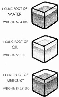
Let us fill a container with a cubic foot
of pure water (see Figure 1-1). We weigh
Figure 1-1. Liquids of different densities.
the contents and find it to be 62.4 pounds.
This is the density of water. Under the same
conditions, a similar volume of oil, such as is
used in a submarine's hydraulic system
weighs approximately 50 pounds; therefore
its density is less than that of water. Under
the same conditions, a cubic foot of mercury
weighs 845.9 pounds; its density obviously
exceeds that of water.
When we speak of the weight of substance,
we actually mean the force, or gravitational
pull, exerted on the substance at the
earth's surface. Every material responds to
the earth's gravitational attraction. To express
the relative density, or specific gravity,
of various liquids and solids, the
gravitational pull upon them is compared to the
gravitational pull upon an equal volume of
water. Water, therefore, is said to have a
specific gravity of 1 and the specific gravity
of any other substance is its density relative
to that of water. Oil has a specific gravity
of (50 x 1)/62.4, or approximately 0.8; that is, its
density is 0.8 of that of water. This explains
why oil floats on water. Mercury, on the other
hand, has a specific gravity of (845.9 x 1)/62.4 or
about 13.5; that is, its density is 13.5 times
as great as that of water; consequently, it
sinks rapidly.
These calculations of the weights of
water, oil, and mercury were made at zero
degrees centigrade (32 degrees Fahrenheit)
and at sea level. At other temperatures and
altitudes, different results would be obtained.
In some engineering calculations, cubic centimeters
and grams are used instead of cubic
feet and pounds. This does not affect specific
gravity, as the relationship between the
weight of a unit volume of any other material
and of water would be the same no matter
what measuring unit were used.
b. Force and pressure. A liquid has no
shape of its own. It acquires the shape of its
container up to the level to which it fills the
container. However, we know that liquids
have weight. This weight exerts a force upon
Figure 1-2. Weight of an isolated column of water.
3
all sides of the container, and this force can
be measured.
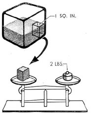
Let us measure this force in a given container
of water (see Figure 1-2).
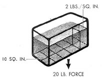
Figure 1-3. Weight=Total Force.
Theoretically, we isolate a vertical column of water
whose base is 1 square inch, extending from
the bottom of the container to the surface of
the liquid. If it were possible to weigh this
pressure, when not otherwise qualified, means
pressure in pounds per square inch.
If the bottom of the container has an
area of 10 square inches and the pressure on
each square inch is 2 pounds, then the force
exerted by the water on the bottom of the
container is 20 pounds (see Figure 1-3). This
is called the total force and is obtained by
the formula:
Total Force = Pressure X Area
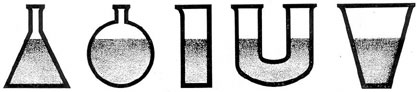
The pressure exerted by a liquid on the
bottom of a container is independent of the
shape of the container, and depends only on
the height and density of the liquid. In all
the dissimilar vessels shown in Figure 1-4,
the pressures are identical as long as the
liquid levels are equal in height.
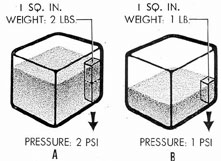
What happens if the levels are not equal?
Then we do have a difference in pressure.
Suppose we have two containers in which the
fluid in A is twice as high as in B (see Figure
1-5). Let us again assume that we have
Figure 1-4. Equal levels produce equal pressures.
column and we found the weight to be 2
pounds, we would be able to say that the one
inch-square column of water exerts a pressure
of 2 pounds per square inch.
Therefore, for unconfined liquids, that is,
liquids in open containers, the pressure in
pounds per square inch exerted by the liquid
on the bottom of the container is equal to
the weight of the liquid on each square inch
of the bottom of the container. It must be
emphasized that the weight of the liquid
is here thought of as a force exerted on
the bottom of the container. Expressed as a
formula, we have:
Pressure = Force per unit area
In this text, as in general engineering
practice, it is understood that the word
weighed a one-inch square column from each
container. The column from jar A weighs 2
pounds and the column from jar B weighs
only 1 pound; therefore the pressure in A is
Figure 1-5. Unequal levels produce unequal pressures.
4
2 pounds per square inch while the pressure
in B is only half of that, or 1 pound per
square inch.
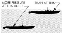
Figure 1-6. Pressure on submerged body increases with increasing depth.
In other words, the greater the depth,
the greater the pressure will be at that depth.
A practical example of the working of this
law is seen when a submarine submerges.
The deeper the submarine goes, the greater
the pressure exerted on its hull by the
surrounding water (see Figure 1-6).
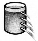
The difference in liquid pressures at various
levels can also be illustrated in the following
way: If we have a tank with openings
of equal size at different heights, as shown in
Figure 1-7, we find that the liquid will flow
out of the lowest opening, where the pressure
is greatest, with much greater velocity than
from the top opening, where the pressure is
lowest.
Figure 1-7. Pressure increases with depth.
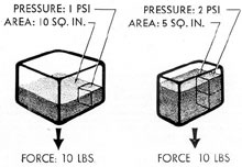
The importance of this principle of hydraulics
can be better understood by considering its
following application.
Figure 1-8 shows two containers. In one
container, we have a pressure of 1 pound per
square inch exerted on an area of 10 square
inches; the total force is 10 pounds. In the
other container we have a pressure of 2 pounds
per square inch applied to an area of only 5
square inches; and the total force is again 10
pounds. We see, therefore, that a high pressure
directed against a small area can be just
as effective as a low pressure directed against
a large area. It follows from this important
law that we are able to reduce the size of
hydraulic units by merely increasing the pressures
in order to obtain the same required
working force-one of the many great advantages
offered by hydraulic power for
applications where the saving of space is a
consideration.
Figure 1-8. Equal total forces from unequal pressures.
1B3. Liquids in enclosed systems. Some of
the general properties of liquids in open containers
have been described. It remains to
discuss how a liquid will behave when
confined, for, example, in an enclosed hydraulic system.
a. Liquids are practically incompressible.
The following two basic principles will help to
explain the behavior of liquids when enclosed:
1. Liquids are practically incompressible
in the pressure ranges being considered. Stated
simply, this means that a liquid cannot be
squeezed into a smaller space than it already
occupies.
2. Therefore, an increase in pressure on
any part of a confined liquid is transmitted
undiminished in all directions throughout the
liquid (Pascal's principle). For example, if
pressure is applied at one end of a long pipe,
the liquid, being practically incompressible,
will transmit the pressure equally to every
portion of the pipe.
5
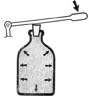
Figure 1-9 shows a simple experiment
which illustrates both these principles. A thin
bottle is filled to the top with a liquid and
tightly corked. A lever is pressed against the
Figure 1-9. Applied pressure Is exerted equally in all directions.
cork to apply a downward force. If sufficient
pressure is exerted, the bottle will suddenly
shatter into a number of pieces, showing that:
a) Liquids are practically incompressible.
b) The applied pressure is transmitted
equally in all directions at once.
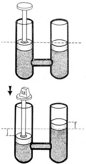
Figure 1-10 illustrates the application of
these principles to a closed hydraulic system.
Two cylinder each having a base whose area
is 1 square inch, are connected by a tube. The
cylinders are filled with liquid to the level
shown, and a piston with a base of the same
area (1 square inch) is placed on top of each
column of liquid. Then a downward force
of 1 pound is applied to one of the pistons.
Since this piston has an area of 1 square inch,
the pressure upon it is 1 pound per square
inch; and since the other piston is of equal
area, the same pressure, 1 pound per square
inch, will be imposed upward upon it.
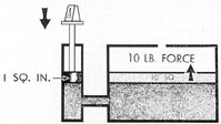
b. Increase of force with area. We are
now ready to consider a remarkable fact which
follows from the principles just discussed, and
which is illustrated in a simplified manner in
Figure 1-11. Here a cylinder whose base has
an area of 1 square inch is connected to another
cylinder whose base has an area of 10 square
inches. Again a force of 1 pound is applied to
the piston in the smaller cylinder; and again
the pressure exerted is 1 pound per square
inch. Now, since this pressure is transmitted
equally in all directions throughout the confined
liquid, an upward pressure of 1 pound per
square inch will be exerted on the piston in the
larger cylinder; and since this larger piston has
a total area of 10 square inches, the total
force exerted on the larger piston is 10 pounds.
Actually, what is happening is that an upward
force of 1 pound is being exerted against
each square inch of bottom surface of the
larger piston; and since the area of this surface
is 10 square inches, the total force is
equal to the downward pressure on the small
piston (1 pound per square inch) multiplied
by the area of the larger piston (10 square
inches); or, 1 (pounds per square inch) X 10
(square inches) = 10 pounds (total force
exerted on larger piston). In other words,
the ratio between the force applied to the
smaller piston and the force applied to the
Figure 1-10. Transmission of equal pressures to equal areas.
6
larger piston is the same as the ratio between
the area of the smaller piston and the area of
the larger piston. Expressed as a proportion,
then, we have:
Force on larger piston/Force on smaller piston =
Area of larger piston/Area of smaller piston
This means that the mechanical advantage
obtainable by such an arrangement is equal to
the ratio between the areas of the two pistons.
Figure 1-11. Equal pressure transmitted to larger area.
It is this principle, discovered by Pascal,
which makes possible the tremendous forces
attainable in certain hydraulic devices, such as
the hydraulic press, and hydraulic hoists.
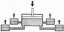
Figure 1-12. Multiple units from a single source
of power.
Now let us once more consider the arrangement
shown in Figure 1-10. Since the
cylinders (and pistons) are of equal area,
pushing the liquid down a distance of 1 inch in one
cylinder will force it upward a distance of 1
inch in the other cylinder. In other words,
the displacements of liquid are equal. But, in
Figure 1-11, since the area of the larger cylinder
is 10 times as great as that of the smaller
cylinder, pushing the smaller piston downward
a distance of 1 inch will move the larger piston
upward only 1/10 of an inch. The ratio between
the displacement of liquid in the smaller
cylinder and the displacement of liquid in the
larger cylinder is once again equal to the ratio
between their areas.
Therefore, we may say that what the
larger piston gains in force, it loses
in distance traveled, so that the amount of work
(force X distance) done by the larger piston
is exactly the same as the amount done by the
smaller piston.
c. Multiple units. It is not necessary to
confine our system to a single line from the
source of hydraulic power. Hydraulic power
may be transmitted in many directions to do
multiple jobs.
Let us connect one cylinder to four others
as in Figure 1-12. Here we apply a force
against the piston in the large cylinder. The
pressure from the large cylinder is transmitted
equally to each of the pistons in the other four
cylinders.
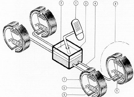
This is actually the method of operation
of an automobile hydraulic-brake system (see
Figure 1-13). The foot pressure on the brake
pedal (1) depresses a piston (2) in the master
cylinder (3). Fluid is forced through the lines
(4) into each of the brake cylinders (5). At
the brake cylinder, two opposed pistons (6)
attached to the brake shoes are forced outward,
pressing the brake bands (7) against the
inside of the wheels (8) to stop their rotation
by friction. Removal of the foot pressure allows
springs (9) at each wheel to restore the
pistons to their original positions and returns
the fluid to the master cylinder where it is
stored in preparation for the next braking
operation.
1B4. Pumps. a. Need for pumps.
In all our
illustrations, we have seen that in an enclosed
system a working force was created by the
displacement of fluid. A weight, acting on a
piston in one cylinder, forced fluid through a
line, thus moving a piston elsewhere in the
system. In the hydraulic brake system, foot
pressure on the pedal displaced the fluid in
the master cylinder and forced it into the
brake cylinders to stop wheel rotation. These
elementary methods are practical enough
where small forces or small volumes of fluid
are required. However, more often a far
greater passage of energy, more or less
continuous in its delivery of fluid, is needed in
a system.
In other words, in practice we usually
need some device which will deliver, over a
Figure 1-14. Principle of a suction pump.
period of time, a definite volume of fluid at the
required pressure, and which will continue to
deliver it as long as we desire it to do so. Such
a device is called a pump.
b. Basic principles of pumps. A hydraulic
pump is a mechanical device which
8
forcibly moves, or displaces, fluids. Various
pumping principles are employed in the different
types of hydraulic pumps, but one fundamental
principle applies to all: a volume of
fluid entering the intake opening, or port, is
moved by mechanical action and forced out
the discharge port.
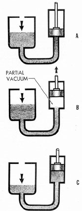
The basic principle underlying the action
of a hydraulic pump is illustrated by the
simplified device shown in Figure 1-14. The
larger chamber, or reservoir, is connected by
a pipe to the smaller chamber, or cylinder. A
piston, free to slide up or down within this
cylinder, is connected by a piston rod to a
pump handle (not shown). The reservoir is
filled with liquid to the height shown.
The illustration shows the device in three
different conditions. At A, the piston
is assumed to be resting squarely on top of
the column of liquid, that is, there is no intervening
space between piston and liquid. At B, the
piston has just been pulled upward by the
pump handle, creating a lower pressure in the
lower half of the cylinder, that is, in the space
now left between the bottom face of the piston
and the top of the column of liquid. At C,
the pressure of the atmosphere, acting on the
surface of the liquid in the reservoir, has forced
the liquid up into the cylinder, filling the empty
space with a compensating amount of liquid
out of the reservoir; the level in the reservoir
consequently falls, as shown.
It should be clearly understood that the
illustration (Figure 1-14) greatly exaggerates
the size of the empty space, or partial, vacuum,
left by the, piston as it rises in the cylinder.
Actually, if a working model of the illustrated
device were to be constructed of glass,
no space of any kind could be observed because
as the piston rises in the cylinder, the
liquid rushes in practically instantaneously
follow the rise of the piston.
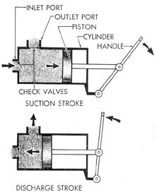
c. The reciprocating pump. The simplest
practical application of this principle is seen
in the hand-operated reciprocating pump, a
simplified version of which is illustrated in
Figure 1-15. Here the inlet and outlet ports
in the cylinder, or pump body, are both in the
same side of the piston. The piston makes a
close sliding fit within the cylinder, reducing
leakage to a minimum, since excessive leakage
destroys the efficiency of a pump. Both the
inlet and outlet ports are equipped with check
valves which permit the liquid to flow in one
direction only, as shown by the arrows.
Figure 1-15. Hand-operated reciprocating pump.
Assume that the intake side of the pump
is connected to a supply of liquid. When we
move the piston to the right, lower pressure
is created in the chamber formed by the piston.
Higher pressure on the fluid outside the
chamber forces fluid in through the inlet
port and fills the chamber. Moving the handle
forward in the opposite direction forces the
fluid out. A check valve at the inlet port
prevents flow there and, since the fluid must find
an outlet somewhere, it is forced out through
the discharge port. The check valve at the
discharge port prevents the entrance of fluid
into the pump on the subsequent suction
stroke. The back-and-forth movement of the
piston in the pump is referred to as reciprocating
motion, and this type of pump is generally known
as a reciprocating-type piston
pump. It may have a single piston or be
multi-pistoned. It may be hand-actuated
or power-driven. The reciprocating piston principle is
conceded to be the most effective for developing
high fluid pressures.
9
d. The theory of suction. In a discussion
of reciprocating pumps, the word suction
may be frequently used. Some writers use it
as though it referred to an independent force
created in the pump itself. It must be emphasized
that suction is merely an expression of
the difference between two unequal pressures.
In this case, the atmospheric pressure,
amounting to 14.7 pounds per square inch at
sea level, acts as a downward force on the
liquid in the reservoir.
Raising the piston, that is, pulling it
away from the surface of the liquid, creates
a partial vacuum, or an area of lower pressure,
between the liquid and the bottom surface of
the piston.
Therefore, as the piston moves upward in
the cylinder, atmospheric pressure forces the
liquid in the connecting pipe to follow the
piston. This fact is the basis of a simple
pumping operation involving "suction." It
also explains why there is a limit to the height
to which a suction pump can move a liquid
under atmospheric pressure, since the liquid
cannot be "pulled" to a greater height by the
pump than atmospheric pressure will push it.
For water at sea level this limiting
height is theoretically 33 feet, but this figure
is never attainable in practice. The imperfections
of actual pumps reduce the limiting
height to 25 feet or less, depending on the
efficiency of the individual pump.
For liquids other than water, the limiting
height varies inversely as the density (weight
per cubic foot) of the liquid; in other words,
the lighter the liquid, the higher atmospheric
pressure will push it when the liquid is
pumped.
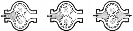
e. The gear pump. Another widely used
type of pump is the rotary gear pump whose
operating principle is illustrated, in simplified
form, in Figure 1-16. Here the mechanical
action which moves the fluid is furnished by
the teeth of the rotary gears. The oil is
trapped by the gear teeth and carried by them
around the outside channels of the pump
body. This sucks in oil at the inlet port (the
left-hand port in the figure), and discharges
it at the outlet port (the right-hand port in
the figure). The oil cannot get back through
the outer channels to the inlet side of the
pump because the gear teeth fit too closely
against the pump body. On the other hand,
the oil cannot pass back between the gear
teeth themselves at the point where they mesh
with each other because they mesh so closely
that, in effect, they form a continuous seal at
this point. Therefore a continuous flow of oil
is set up in the direction shown by the arrows.
This flow continues as long as the gears
continue to rotate. Pumps using the gear
principle are popular because of their quiet
performance and because their simplicity of
design results in relative freedom from service troubles.
1B5. Hydraulic fluids. Almost any free-flowing
liquid is suitable as a hydraulic fluid,
as long as it will not chemically injure the
hydraulic equipment. For example, an acid,
although free-flowing, would obviously be
unsuitable because it would corrode
the metallic parts of the system.
Water, except for its universal availability,
suffers from a number of serious defects as
a possible hydraulic fluid. One such defect is
that it freezes at a relatively high temperature,
and, in freezing, expands with tremendous
force, destroying pipes and other equipment.
Also, it rusts steel parts; and it is rather
heavy, creating considerable amount of
inertia in a system of any size.
Figure 1-16. Rotary gear pump.
10
The hydraulic fluid used in submarine
hydraulic systems is a light, fast-flowing
lubricating oil, which does not freeze or even
lose its fluidity to any marked degree even at
low temperatures, and which possesses the
additional advantage of lubricating the internal
moving parts of the hydraulic units through
which it circulates.
Since this oil, a petroleum derivative,
causes rapid deterioration of natural rubber,
synthetic rubber is specified for use in these
systems as packing and oil seals.
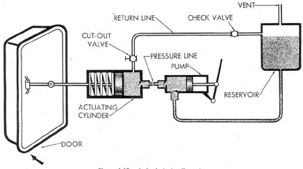
1B6. A simple hydraulic system. On the basis
of the explanation of basic hydraulic principles
just given, it is possible to construct a
simple, workable hydraulic system which will
operate some mechanical device. For example,
such a system might open and close a door,
and hold it in either position for any desired
interval.
a. Basic units of a hydraulic system.
Such a system is illustrated in Figure 1-17. It
necessarily includes the following basic
equipment, which, in one form or another, will
be found in every hydraulic system:
1. A reservoir, or supply tank, containing
oil which is supplied to the system as needed
and into which the oil from the return line
flows.
2. A pump, which supplies the necessary
working pressure.
3. A hydraulic cylinder, or actuating cylinder,
which uses the hydraulic energy developed in
the pump to move the door.
4. A cut-out valve, by means of which the
pressure in the actuating cylinder may be
maintained or released as desired.
5. A check valve, placed in the return
line to permit fluid to move in only one direction.
6. "Hydraulic lines," such as piping or
hose, to connect the units to each other.
The supply tank must have a capacity
large enough to keep the entire system filled
with oil and furnish additional oil to make
good the inevitable losses from leakage. The
tank is vented to the atmosphere; thus
atmospheric pressure (14.7 pounds per square
inch) forces the oil into the inlet, or suction,
side of the pump, in accordance with the
principle explained in connection with Figure
1-14. The tank is generally placed at a higher
level than the other units in the system, so
that gravity assists in feeding oil into other
units.
The pump is the hand-operated, reciprocating
piston type illustrated in Figure 1-15.
Figure 1-17. A simple hydraulic system.
11
The surface of the pump piston in contact
with the hydraulic fluid has an area of 1
square inch.
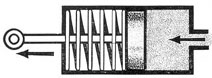
The hydraulic cylinder (see Figure 1-18),
which is the simplest type of hydraulic motor,
contains a spring-loaded piston, with a piston.
rod that extends through one end of the
Figure 1-18. Single acting hydraulic cylinder.
cylinder. This piston rod, when connected to the
door, supplies the mechanical motion which
opens and closes the door. The surface of the
piston in contact with the hydraulic fluid has
an area of 2 square inches.
The cut-out valve is hand-operated. When closed, it shuts off the line between the
actuating cylinder and the supply tank,
preventing the oil under pressure in the cylinder from
escaping into the return line; when opened, it
releases this pressure, allowing the loading
spring inside the cylinder to expand, and the
oil in the cylinder to escape back into the
supply tank.
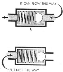
The check valve (see Figure 1-19) is of the
ball spring type. It is shown in two positions.
At A, fluid entering the right-hand port under
pressure sufficient to overcome the tension of
the spring has unseated the ball, allowing oil
to pass out through the other port in the direction
shown by the arrow. At B, lower
pressure on the line entering, the right-hand
port has caused the oil pressure and tension
spring to reseat the ball check, blocking off
the right-hand port, and preventing movement
of oil in that direction. The ball, machined
to a smooth finish, fits closely into the seat,
making a tight seal.
b. Operation of the system. Let us assume
that the force necessary to move the
door is 200 pounds. Let us further assume
that the mechanical advantage of the handle
and the muscular effort applied to it result in
a force of 100 pounds exerted against the
pump piston. Therefore, oil from the piston
is forced into the actuating cylinder at a
pressure of 100 pounds per square inch. This,
then, is the working pressure of the system,
the pressure at which fluid is delivered to the
actuating cylinder.
Since the piston in the actuating cylinder
presents an area of 2 square inches to the fluid
-twice as great as the area presented by the
pump piston- the total force acting against
the piston of the actuating cylinder is 200
pounds, enough to overcome the resistance of
the loading spring and close the door. To
operate the system, the cut-out valve is closed
and the pump handle is moved to the right,
drawing in a quantity of oil from the reservoir
("suction stroke"). Then the handle is
moved in the opposite direction ("pressure
stroke"). The check valve to the reservoir
line closes and the check valve to the pressure
line leading to the actuating cylinder opens,
delivering oil to the actuating cylinder at a
pressure of 100 pounds per square inch. The
check valve in the actuating cylinder opens,
Figure 1-19. Ball check valve.
allowing the oil to enter. The closed cut-out
valve prevents the oil from entering the return
line, and the oil, acting against the
actuating cylinder piston with a total force
of 200 pounds, pushes it to the left,
overcoming the resistance of the loading spring and
closing the door.
12
The door will remain shut as long as the
cut-out valve is in the closed position. As
soon as the valve is turned to OPEN, the piston
in the actuating cylinder is returned to
its original position by the spring. The door
opens. Fluid that was locked in the cylinder
will be forced out through the return line
back to the reservoir. It cannot return
through the pump because of the check valve.
Back-flow of the fluid from the tank into the
return line is also prevented by a check valve.
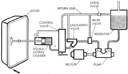
1B7. A power-driven hydraulic system. The
door-operating system illustrated in Figure
1-17 is far simpler than is usually found in
actual service. It has the obvious disadvantage
that instantaneous opening of the door is
not possible because pressure is built up
slowly by hand pumping.
a. Units of a power-driven hydraulic
system. Figure 1-20 illustrates a system in
which a motor-driven pump is substituted for
the hand pump, a double acting actuating cylinder
for the spring-loaded single acting
cylinder in Figure 1-17, and including a control
valve, an unloading valve, and an automatic
relief valve, in addition to the supply
tank, or reservoir, and the return line check
valve, which are the same as in the first
system.
Automatic pumping will give immediate
pressure for use at the actuating cylinder
whenever it is needed.
In the simplified system, the door was
actuated by a single acting cylinder. Oil was
kept in or released from the cylinder by a
simple "on-and-off" valve. For more efficient
and positive actuation, this will be replaced
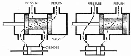
by a double acting cylinder (see Figure 1-21).
In such a cylinder, the piston can move in
either direction to open or close the door.
The piston is locked in the desired position
by the hydraulic fluid, which enters either
side of the piston as required and remains
there until forced out. Since the flow of the
fluid must be directed to either of two sides,
a valve, which selects the direction of flow, is
installed in the line. This is called a control
valve. Control valves vary with the specific
application, but generally they are equipped
with four ports. Two are connected to the
actuating cylinder at either side of the piston.
A third port is the pressure port and receives
fluid from the pump. The fourth port returns
surplus fluid either back to the reservoir or
elsewhere in the system. Figure 1-22 shows
a piston-type, or spool-type, control valve, so
called because of the internal piston, or spool,
which, as it slides into various positions
Figure 1-20. Power-driven hydraulic system.
13
inside the valve body, directs the flow of fluid
by opening and closing the desired combination of ports.
The grooves permit flow between two of the ports,
while the lands at
Figure 1-21. Double acting hydraulic system.
both ends of the spool block off the remaining ports.
NOTE: There are types of spool valves
other than the type shown in Figure 1-22.
In order to have pressure at all times for
the immediate operation of the door, the
power-driven pump turns continuously.
However, a pressure of 100 pounds per square inch
in the cylinder is all that is necessary to move
the door, and any pressure greatly in excess
of this may damage some of the equipment.
To guard against this danger, a relief valve is
placed in the pressure line beyond the pump.
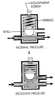
The usual construction of a relief valve
consists of a valve body containing a valve
which is held against a seat by a spring whose
tension can be adjusted for any desired operating
pressure (see Figure 1-23, A). When
the fluid pressure is greater than the spring
tension, the spring is compressed and unseats
the valve (see Figure 1-23, B), thus bypassing
the fluid back into the reservoir.
b. Friction, turbulence, and thermal expansion.
Oil, or in fact any liquid driven at
high speed through an enclosed system, soon
rises in temperature. This is caused by two
factors:
1. Friction of the oil against the interior
of the pipe lines, valves, and other parts.
2. Turbulence of the oil itself; for
example, the swirls and eddies caused in the oil
by its coming into contact at relatively high
velocity with internal bends, its sudden
emergence into wider or narrower places in
the system, and so forth.
Friction is caused by the collision of
individual oil molecules with the solid walls of
pipes and other parts.
Turbulence causes another kind of friction,
which is the result of the collisions of
oil molecules with each other. Both kinds of
Figure 1-22. Spool-type control valve.
14
friction cause a loss of power through heat.
The rise in temperature of the oil is caused
by this friction-heat. The heat also causes a
thermal expansion of the oil. Therefore, both
heating and expansion inevitably occur
whenever hydraulic fluid is pumped continuously
through the system, even though it is
not in use.
c. Power losses. When we compute the
power necessary to operate our system,
allowance must be made for power losses which
Figure 1-23. Principle of the relief valve.
cannot be prevented. A pressure of 100 pounds
per square inch acting upon a piston whose
base has an area of 2 square inches should
theoretically provide a working force of 200
pounds. However, this is possible only theoretically.
In practice, as fluid passes through the
hydraulic lines, it meets resistance from the
inner pipe walls. Some of the energy imparted
to the oil by the pump is lost in friction. At
low rates of flow, the fluid will flow
in fairly straight lines. At high rates of flow,
the flow becomes turbulent and friction losses
increase. Friction and turbulence losses usually
range between 10 percent and 20 percent
of the developed power. Instead of getting
a 200-pound force to open the door in our system,
we may obtain a force of only 160 pounds
because of these losses. Therefore, in
conformance with good hydraulic design, we must
either increase the pump pressure, enlarge the
piston area in the actuating cylinder, or
increase the size of the pipes and passages to
compensate for the loss of energy.
d. Need for a bypass valve in a power-driven system.
Since friction always increases
with rate of flow, it follows that the greater
the rate at which oil circulates in the system
-all other things being equal- the more the
oil will be heated. Also, the greater the length
of the circuit traveled by the fluid during this
free, or no-load, circulation, the greater the
friction surface and consequent heating. To
reduce both the pressure and the length of
circuit to a minimum, a bypass valve is provided.
This valve returns the oil from the
pressure side of the pump directly to the
reservoir, or supply tank, without its first
having traveled through the rest of the system.
Thus, the bypass valve in effect "short-circuits"
the oil pressure from the pump,
leaving the oil in the remainder of the system
inactive, and reducing the pressure at which
the oil circulates to atmospheric pressure.
A bypass valve may be operated by hand
or automatically in the same manner as a
relief valve, or by remote control. When automatic,
it is known as an automatic bypass or
unloading valve. In actual practice, an automatic
bypass arrangement requires more
complex equipment than is shown in Figure
1-23. It is shown here merely in a schematic
view, greatly simplified for explanatory purposes.
e. Operation of system using power-driven pump.
Since the power-driven pump
has been turned on and has come up to its
operating speed, hydraulic power at the working
pressure becomes constantly and instantaneously available.
The automatic bypass,
15
or unloading valve, and the relief valve will
relieve any pressure greatly in excess of this.
To close the door, the control valve
handle is turned so that fluid under pressure
is directed to the side of the actuating
cylinder which is marked d; the movement of the
piston closes the door. It also pushes out
the fluid which has been trapped on the side
of the cylinder marked o. The expelled fluid
reenters the system through the return line
of the control valve and flows back to the
reservoir. To lock the door shut, the control
valve handle is turned to its neutral position;
the door will then remain shut until the
control valve is moved to the OPEN position.
To open the door, the control valve is
turned so that fluid enters the actuating
cylinder at o. This moves the piston back to the
d side of the cylinder and forces out the fluid,
which was delivered there when the door was
originally closed. The fluid is then returned
to the system.
Observe that the two lines connecting the
actuating cylinder to the control valve have a
dual function. Depending upon which way
the hydraulic fluid is directed, one side
becomes the pressure line and the other the
return line. A change in direction reverses
their functions.
During those intervals between opening
and closing the door, the fluid circulates
between the pump and the reservoir; the
automatic bypass valve short-circuits the
pressure from the pump, as explained above.
1B8. Practical hydraulics on the submarine.
In an extremely simplified form, we have, just
described a basic hydraulic system. In actual
appearance the hydraulic equipment installed
aboard a submarine may not closely resemble
such basic units. Nevertheless, the same
principles govern both systems.
In a submarine, a single system actuates
a multitude of devices and appears to be far
more complete. Stripped to its essentials,
each unit is moved by a hydraulic motor
which receives its power in the form of fluid
pressure from a central pumping plant. The
liquid moves through pipes and its flow is
directed by valves. Essentially, therefore, the
submarine hydraulic system does not deviate
in principle from the simple system we
designed and discussed.
Actually a submarine employs not one,
but four separate hydraulic systems:
1. The steering system, which operates
the rudder.
2. The stern plane system, which tilts
the stern diving planes to dive or rise.
3. The bow plane tilting system, which
tilts the bow diving planes to rise or dive.
4. The main hydraulic system, which operates the following equipment.
a.
Flood and vent valves.
b.
Main air induction valve.
c.
Bow plane rigging.
d.
Windlass-and-capstan in bow.
e.
Main engine outboard exhaust valves (in some installations hydro-pneumatic).
f.
Torpedo tube outer doors.
g.
Emergency power for steering system if failure occurs.
h.
Emergency power for bow plane tilting system.
i.
Emergency power for stern plane tilting system.
j.
Periscope hoists.
k.
Vertical antenna hoist.
l.
Sound heads.
These functions may vary somewhat
among different submarine classes. They
represent an accurate picture of the usefulness
of hydraulics as applied to the submarine.
Moreover, the functions of hydraulics are constantly
increasing because hydraulics
has proved to be superior as a source of
power. Let us summarize its advantages:
a.
Lighter weight of units.
b.
Controllability in small movements.
c.
Low inertia of moving parts.
d.
Simplicity.
e.
Positive operation.
f.
Self-lubrication.
g.
Little wear or corrosion.
h.
Relatively silent operation.
i.
System not apt to be disrupted by salt spray or water.
j.
Less maintenance.
We are now ready in succeeding chapters
to examine each of the systems in detail to
see how each system works and how to keep
it working in the vent of trouble.