GYROCOMPASS, AUXILIARY GYROCOMPASS,
AND DEAD RECKONING ANALYZING
INDICATOR AND TRACER SYSTEMS
A. THEORY OF THE GYROCOMPASS
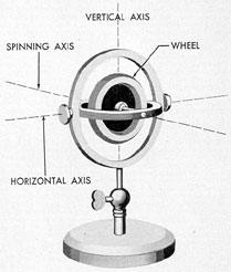
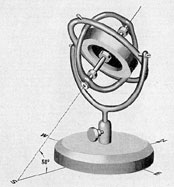
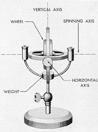
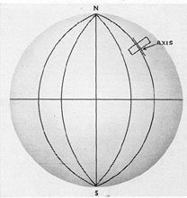
17A1. Construction of a gyroscope. A free
gyroscope is a wheel, constructed similarly to a
flywheel and suspended with 3 degrees of freedom.
(See Figure 17-1.) The gyroscope may spin
around the spinning axis, and turn around the
horizontal axis and the vertical axis. The center
of mass of the wheel is at the intersection of the
3 axes.
The gyro wheel should be constructed so as
to have as much material near the rim as practicable
and to run at high speeds. Naturally it
must also be well-balanced and be as frictionless
as possible.
Figure 17-1. A free gyro.
17A2. Properties of a gyroscope. Gyroscopic
phenomena are exhibited in all rotating
bodies. Common examples are a spinning top, a
car going around a curve, and a moving bicycle.
All known gyroscopic phenomena are dependent
upon two properties of the gyroscope:
1) rigidity in space and 2) precession.
Rigidity in space is manifest in the gyroscope's
tendency to remain pointing in the same
direction at all times or to maintain its plane of
spin parallel to itself. This is based on Newton's
First Law of Motion which states: Every body
continues in its state of rest or of uniform
motion in a straight line, unless it is compelled by
external forces to change that state.
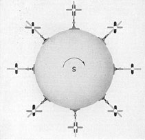
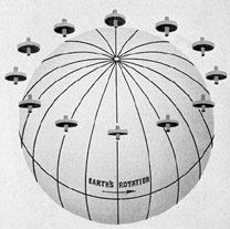
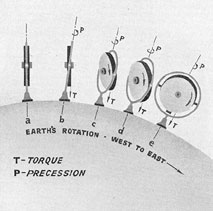
17A3. Apparent rotation. If a gyroscope
having complete freedom is spun continuously
and is set at the earth's equator with its
spinning axis horizontal in the east and west
direction (see Figure 17-2), the wheel while
spinning also apparently rotates about a horizontal
axis that forms a right angle with the spinning
axis. This apparent rotation proceeds at the rate
of a single revolution in a day. Actually, however,
the gyro spinning axis remains parallel to
its original position in space, though the gyro is
carried along with the earth by the revolution
of the latter about its polar axis. Thus, as shown
in Figure 17-2, at the end of 3 hours the west
end of the axle, viewed looking north, is depressed
45 degrees, and at the end of 6 hours it is vertical
to the surface of the earth, having been
carried through 1/4 of a revolution in 1/4 of a
day. At the end of 12 hours, the axle is again
horizontal, but its ends are reversed as viewed
by an observer looking north. Actually the gyro
axle still is parallel to its original position in
222
space and is pointing in its original direction in
space. The apparent motion continues, and at
the end of a complete revolution of the earth
in 24 hours, the original position of the gyro
axle is regained.
Figure 17-2. Gyro spinning at equator with its
axis horizontal.
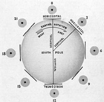
If a gyro with complete freedom is spun
with the gyro axle horizontal at either the North
or South Pole of the earth the axle will be at a
right angle to the polar axis of the earth. But
since a spinning gyro maintains the direction
of its plane of rotation in space and the direction
of its axis in space, it has an apparent motion
about its vertical axis (Figure 17-3).
It should be noted that at the poles the apparent
rotation is entirely about a vertical axis,
but at the equator the apparent rotation is entirely
about a horizontal axis.
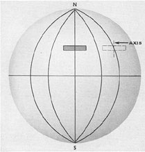
If a gyro with complete freedom is spun at
an intermediate latitude, with the gyro axle
horizontal and in the meridian, the gyro axle
will neither be parallel to nor at a right angle
to the earth's axis, but will be at an angle to it
equal to the latitude, as shown in Figure 17-4.
Rigidity of direction in space, or gyroscopic
inertia, will therefore cause the gyro axle to rotate
apparently about a line (A-B, Figure 17-4)
passing through the center of the gyro parallel
to the polar axis of the earth. This apparent
movement of the gyro axle corresponds with a
daily period (Figure 17-5) and is partly about
the vertical line passing through the center of
the earth, and partly about the horizontal axis
of the gyro.
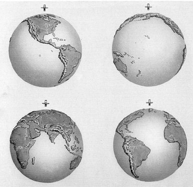
17A4. Resting position. If the gyro is set
spinning at the equator, with the gyro axle in
the meridian and horizontal, the gyro axle will
remain horizontal and in the meridian. Thus,
the axle would continue to point north. This is
equivalent to pointing north and parallel to the
earth's polar axis, as illustrated in Figure 17-6,
and there would be no apparent rotation. The
gyro axle remains parallel to the earth's axis,
though carried around it by the earth's rotation.
Furthermore, the gyro axle remains stationary
relative to the surroundings on the earth, although
still rigid in direction relative to space.
A condition in which those conditions prevail
is termed a resting position, and it is the only
resting position at the equator. The numbers in
Figure 17-6 indicate the hours.
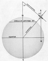
At high latitudes, the only true resting position
for a gyro with complete freedom is that
in which the gyro is set spinning with its axis
parallel to the earth's polar axis. For latitude
50 North, the gyro, spinning in its true resting
position, would be tilted so that the gyro axle
would make an angle with the horizontal equal
to the angle of latitude as shown in Figure 17-7,
with the gyro axle in the meridian and the north
end of the gyro axle pointing upward.
However, there are reasons for this tilt being
impracticable with respect to gyrocompasses. A
gyrocompass must have the gyro axle nearly
horizontal. Means must therefore be applied to
secure a resting position in the meridian and in
the horizontal. Accordingly the axle of the gyrocompass
is parallel to the polar axis of the earth
only when the compass is operating at the
equator.
17A5. Effect of applied force of translation.
A completely free gyroscope may be moved anywhere
or carried around by the earth's rotation
without altering the direction of its axle relative
to space. It is therefore unaffected by forces of
translation.
223
Figure 17-3. Gyro spinning of pole with its axis horizontal.
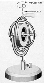
17A6. Precession. The gyroscopic property
referred to as precession may be demonstrated
by applying a force to the gyroscope so as to
tend to change the plane of rotation of the spinning
wheel.
If the gyroscopic wheel is spinning in the
upward direction as indicated by the arrow B
and a force is applied to turn the gyroscope
about the horizontal axis (Figure 17-8), it will
be found that there is a great resistance to the
force, and instead of motion taking place in the
direction of the applied force the wheel turns
around in the direction of the arrow labelled
PRECESSION. It continues to turn in that direction
during the application of the force until
the plane of spin of the wheel coincides with the
plane of the force or until the force is removed.
When the direction of spin is reversed and the
experiment is repeated (Figure 17-9), similar
phenomena are exhibited, except that the wheel
turns around in the opposite direction. The observed
motion, precession, is always about an
axis at a right angle to the axis of the impressed
force.
17A7. Rule for precession. By comparing
the final positions taken under conditions represented
in Figures 17-8 and 17-9, respectively,
it may be seen that in these experiments the
wheel not only sets its place of rotation into
coincidence with that of the force, but that the
224
Figure 17-4. Gyro spinning at intermediate positions.
direction of rotation is also in coincidence.
The experiments may be repeated in many
ways and the results will always be as expressed
Figure 17-5. Gyro wheel with its rotating axis set in
north-south position and level away from the equator
moves about its horizontal and vertical axes.
Figure 17-6. Resting position of a gyro spinning
at equator.
Figure 17-7. Resting position of a gyro spinning
at high latitudes.
by the following rule: The movement is such
as to place the plane and direction of spinning
rotation of the wheel in coincidence with the
plane and direction of the force by the shortest
path.
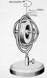
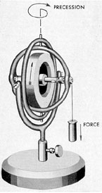
17A8. Continuous precession. When the applied
force acting on the gyro system is arranged
225
Figure 17-8. Effects of applied force on vertical axis
with gyro wheel spinning in upward direction.
Figure 17-9. Effects of applied force on vertical axis
with gyro wheel spinning in downward direction.
Figure 17-10. Continuous precession.
so that the force is constant, precession becomes
continuous. This is illustrated in Figure 17-10,
which shows a spinning gyro with horizontal
axis and with :a weight hung on one end of the
axle. The spinning wheel will turn about its vertical
axis as indicated in Figure 17-10. The wheel
continues to follow the weight and continuous
precession results. Precession ceases immediately
upon removal of the weight.
17A9. Relation of applied force to precession. The
speed of precession is directly proportional to the
applied force, and inversely
proportional to the weight of the spinning wheel
and to its speed in rpm.
226
B. FUNDAMENTAL CHARACTERISTICS OF THE GYROCOMPASS
17B1. Characteristics of the gyrocompass.
It has been shown that if a spinning gyro wheel
is placed on land at the equator, with the gyro
axle parallel to the earth's polar axis, it will
remain in the meridian, because there is no
force tending to deflect it. However, when it is
placed on a ship it is subjected to the disturbing
forces of a ship's motion, which deflect it
from the meridian.
To be of use as a compass on board ship,
the gyro wheel must remain rigidly in the
meridian at any latitude and must be unaffected
by the ship's motion.
Hence, a gyrocompass must be made to seek
and hold the meridian against the friction of its
supports and other disturbing forces. For example, a ship changing course turns about the
compass, and as friction cannot be entirely
eliminated, the friction of its support tends to
deflect the gyro.
17B2. North seeking. The Arma compass is
a pendulous gyro. It is made north-seeking by
placing a weight below the spinning axis as
shown in Figure 17-11.
Let us assume that the gyroscope is at the
equator with its spinning axis horizontal and
pointing to the east of the meridian. The north
end of the gyroscope will appear to tilt upward
since the gyro maintains its direction in space
as the earth revolves under it. Gravity will
attract the weight toward the center of the earth
-straight down as shown in Figure 17-12. This
pull of gravity has the same effect as an applied
force or torque around the horizontal axis. Due
to the direction of rotation of the wheel, clockwise
looking at the south face, the precessional
motion will take place to the west as shown in
Figure 17-12.
As the upward tilting increases, the torque,
or gravity pull, increases with a corresponding
increase in the rate of precession toward the
west. When the gyro is on the meridian, the
maximum upward tilt of the axis is attained
and the rate of precession is greatest. The tilt
will now be reduced and with it the rate of precession,
until the north end of the axis is
horizontal and the torque is zero. The precessional
motion is also zero because there is no torque.
But the earth continues to rotate under the
gyroscope, so the gyro axis now has a slight tilt
downward, and the torque or pull is reversed
with the corresponding reversal of direction of
precession. This downward tilting continues until
the axis is pointing along the meridian where
the precessional motion is the most rapid toward
the east. At this point, the tilt diminishes, the
torque diminishes, and finally the gyro axis is
again pointing horizontally at the point where
the oscillation first started.
Figure 17-11. Simple pendulous type gyro.
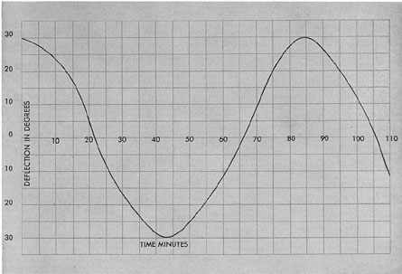
The north end of the pendulous gyroscope
oscillates back and forth across the meridian in
a period of approximately 84.3 minutes. On each
passage of the meridian of the north end of the
spinning axis, the gyro is tilted either upward
or downward. Also the axis points to the meridian
only momentarily, making it useless as a
navigational instrument. (See Figure 17-14.)
In order to make a compass of a pendulous
227
Figure 17-12. Effect of gravity and resultant
precessional motion.
gyroscope it is necessary to cause it to point
along the meridian at all times. To do this the
oscillations must be damped out.
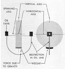
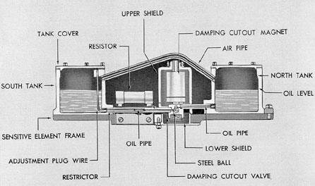
17B3. Damping the oscillations. In order to
damp the oscillations, the Arma compass employs
an arrangement called an oil ballistic. It
consists of two tanks located on the north and
south sides of the gyro wheel and connected at
the bottom by a pipe.
Let us assume that the north end of the
gyro axis points to the east of the meridian, with
the two tanks secured as shown in Figure 17-13,
the axis horizontal, and with equal amounts of
oil in both tanks.
The gyro axis then tilts upward, due to the
earth's rotation, and at the same time oil flows
to the south or low tank. The pendulous mass
of the weight causes the gyro to precess toward
the meridian, to the west. During this period oil
continues to flow from the north tank to the
south tank. The rate of flow is low, due to the
resistance offered by the small passage in the
pipeline. By the time the north axle of the gyro
has reached the meridian, a considerable quantity
of oil has been transferred from the north
tank to the south tank. The excess oil gathering
in the south tank provides a force which opposes
the force of the weight. The effect of the
weight is, therefore, reduced as the gyro axle
approaches the meridian and the rate of precession
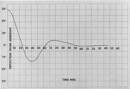
is materially reduced. By properly proportioning
the gyro's pendulous factor and the
rate of transfer of oil, the initial oscillation may
be completely suppressed or damped in about
2 1/2 cycles. (See Figure 17-15.)
Figure 17-13. Oil ballistic arrangement for damping
oscillation.
17B4. Continuous precession toward the
meridian. In order that the gyro may be
constantly in the meridian at all latitudes, it must
be made to precess continuously about its
vertical axis to the west as fast as the earth is
carrying the gyro off to the east.
In northern latitudes the gyro, if it maintains
its direction in space, is no longer in the
meridian, and hence after several hours it would
indicate an error of large magnitude as shown in
Figure 17-16 (dotted lines).
This constant westerly precession about the
vertical axis is caused by a turning force about
the horizontal axis. A force about the horizontal
axis takes place only when the gyro is tilted upward
or downward. In northern latitudes, the
Arma gyro settles in the meridian with a slight
upward tilt of the rotor axis, causing a turning
force to the west due to the pendulous factor
which keeps the compass in the meridian as
shown in Figure 17-17.
228
Figure 17-14. Effect of undamped oscillation.
C. CONSTANT MOTION ERRORS
17C1. General. This section deals with the
errors encountered in the gyrocompass and the
method of correcting them in the pendulous
type compass when installed on board ship.
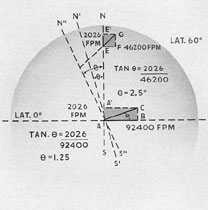
17C2. Speed error. The magnitude of the
speed error is dependent upon the speed, course,
and latitude of the ship in which the compass is
installed. A ship at the equator is being carried
around by the earth's rotation at a velocity of
900 knots. At any latitude other than the equator,
this velocity becomes 900 times the cosine
of the latitude. If a ship is steaming due west,
its speed opposes that of the earth; if steaming
due east its speed is added to the movement of
the earth. Neither course causes a speed error,
but both have a slight effect on the directive
force of the wheel.
If, however, a ship starts at the equator and
sails due north, its speed is at a right angle to
the speed with which the rotation of the earth
is carrying the gyrocompass around in space.
Assume that the vessel in Figure 17-18 starts at
A and is making a speed of 2,026 feet per minute
or 20 knots, along the course line A-A'; the
speed of rotation of the earth is 92,400 feet per
minute along A-B. The actual speed and direction
in which the compass is being carried around
in space is A-C, and the actual axis about which
it is carried around is not the earth's polar axis
N-S, but an axis at a right angle to A-C. The
gyro axle will, therefore, settle on a line N'-S'
and not on the true meridian. The true north
will be toward the east of the indicated north by
an angle N'-A-N which will be 1.25 degrees for a speed
of 20 knots. If the ship starts from the equator
and sails due south, the deviation will be toward
the opposite side, that is, the true north will be
west of the indicated north. If the course is
neither due north nor due south, the deviation
will have a value between zero and 1.25 degrees. If the
ship is at 60 degrees north latitude, steaming at 2,026
feet per minute, or 20 knots, due north as at
E-E', and the earth's rotation at this latitude
229
Figure-17-15. Effect of damped oscillation.
E-F is 46,200 feet per minute, the compass is
being carried around with a velocity E-G and
is being rotated about an axis N"-S" at a right
angle to the resultant E-G. The axle will align
itself with N"-S". Thus, in this latitude and at
the given speed, the true north will be 2.5 degrees
eastward of that indicated by the compass. On
northeasterly-or northwesterly courses, the
deviation will be between zero and 2.5 degrees.
17C3. Ballistic deflection error. In Figure
17-19, the gyro axis is assumed to be pointing
along OA. ON is the true north. The angle NOA
is the speed error for an assumed course of north
and an assumed speed of 20 knots. For a true
east course for any speed or latitude, the speed
error is zero. Therefore, the axis of the gyro
points along ON if the course is east. Let us
suppose that the ship, which is on a northerly
course and is traveling at a speed of 20 knots,
should change to an easterly course. This change
of course is made in about 2 minutes. During
this time, the north end of the gyro must
precess to the east so that by the time the ship is
headed east, the axis of the gyro will point along
the line ON. If the gyro, by the time the ship
is on an easterly course, is not pointing along
the meridian ON, it will produce an erroneous
reading on the compass and its repeaters.
Fortunately, the north end of the gyro will
have a tendency always to precess toward its
proper settling point on a change of course.
If the compass is to have the proper ballistic
deflection during the time that the vessel is
actually changing course, it must have a definite
amount of pendulousness for the latitude which
will make it precess exactly to the settling point
required for the new course in a deadbeat manner.
The ballistic deflection error is prevented
in the Arma compass by varying the speed of
the gyro rotors in accordance with the cosine of
the latitude of the vessel's position. This
variation in speed is effected by changing the speed
of the motor generator through a field rheostat
on the control panel.
230
Figure 17-16. Gyro axis parallel to the north-south axis.
Figure 17-17. Gyro axis parallel to the meridian.
17C4. Ballistic damping error. The oil
damping arrangement of the Arma compass allows a
small quantity of oil to flow from one
tank to the other when the compass is subjected
to the inertia forces caused by acceleration or
deceleration of the ship during a change of
course or speed so that an unbalanced condition
is set up. This unbalanced condition results in
a precession about the vertical axis and causes
an oscillation which must be damped out in the
Figure 17-18. Speed course latitude errors.
Figure 17-19. Ballistic deflection error, ship on
northerly course.
regular manner. In all the later Arma compasses,
damping is eliminated for changes of
course of 15 degrees or over, thereby eliminating
this error. This is accomplished by a solenoid-operated
valve controlled by contacts in
the follow-up system.
17C5. Quadrantal errors. Centrifugal forces
resulting from roll and pitch are neutralized in
the Arma compass by maintaining uniform distribution
of the sensitive element masses in the
horizontal plane. This is accomplished by supporting
the sensitive element on a hollow steel
231
sphere which floats in a concentric tank of mercury.
Acceleration forces caused by roll and pitch
are neutralized in the Arma compass by east-west
stabilization of the sensitive element. This
is accomplished by using two gyroscopes instead
of one. In this way, swinging of the compass in
the east and west direction is prevented,
giving both east and west stabilization as well
as north and south.
17C6. Latitude error. The Arma compass
settles on the meridian in a tilted position and
has no latitude error, hence correction for this
error is not required.
17C7. Speed error. The Arma compass has
a correcting mechanism that compensates for
speed error so that the true course readings are
indicated on the compass card and repeaters.
D. UNITS OF THE COMPASS EQUIPMENT
17D1. Units comprising the compass equipment.
The principal units of the compass
equipment are as follows:
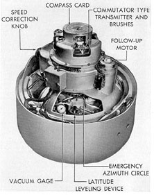
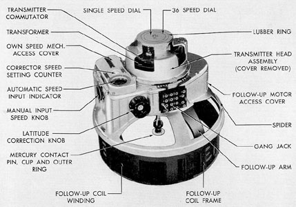
1. Master compass (Figure 17-20). This
includes the north-seeking element, its housing,
and a follow-up mechanism.
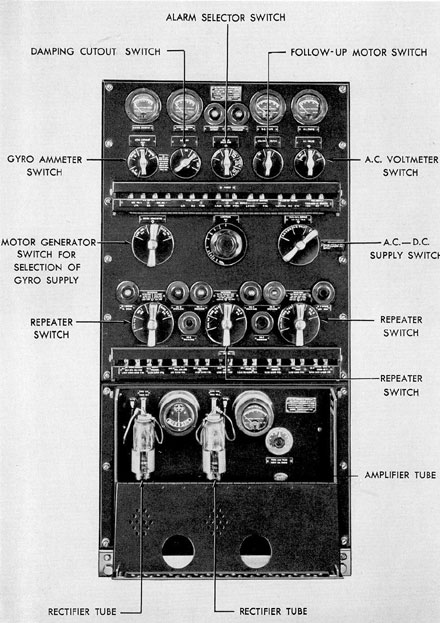
2. Control panel (Figure 17-21). This
panel carries meters, switches, and ballistic
adjustment for the master compass.
3. Repeater panel. This panel is mounted
directly below the control panel, on the same
frame. It carries switches for controlling the
repeater compasses.
4. Follow-up panel. This panel carries
the vacuum tubes that drive the follow-up
mechanism of the master compass. It is mounted
directly below the repeater panel and on the
same frame.
5. Motor generator set. This unit converts the
ship's supply to a three-phase, variable
frequency supply for driving the gyros.
6. Repeater compasses. These receive and
indicate the ship's heading at remote stations.
Figure 17-20. Arma master compass installed,
binnacle cover removed.
232
Figure 17-21. Arma master compass control, repeater and follow-up panels.
233
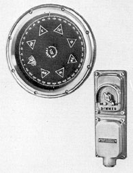
Figure 17-22. Single dial repeater with dimmer.
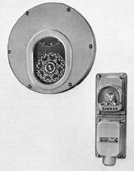
Figure 17-23. Conning tower double dial steering unit
with dimmer switch.
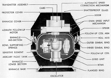
17E1. Components of the master compass.
The master compass shown in Figure 17-25 is
the principal unit in the compass equipment.
For purposes of description, the master compass
may be divided into its major parts as follows:
17E2. Binnacle stand. The binnacle stand
(Figures 17-25 and 17-26) which supports and
encloses the whole master compass, is made in
3 sections. The center section is cylindrical and
connects the upper and lower sections. The bottom
of the lower section is bolted to the binnacle base.
The midsection carries the gimbal rings. It
is rigidly bolted to the lower section. Inside the
lower section near its base, 4 terminal blocks
are fastened, for making connections with the
control panel.
The binnacle top section is a cover attached
to the midsection by latches. Its upper surface
is shatterproof glass through which the compass
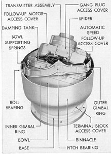
Figure 17-25. Master compass with cover removed
showing position for 15 degree pitch and 35 degree roll.
card may be read. Near the forward and after
sides of the cover are 2 hinged doors for gaining
access to the speed correction knob and other
parts. These doors are provided with hasps and
padlocks.
17E3. Gimbal rings. To provide a relatively
stable support for the compass, the frame,
consisting of bowl and spider, is supported
on gimbal rings (see Figure 17-25) within the binnacle
stand. The outer ring is trunnioned fore and aft
in the binnacle midsection on ball bearings
mounted in bakelite bushings to insulate the
rings from the binnacle. The inner ring is
trunnioned athwartship within the outer ring. To
prevent the compass frame from swinging
excessively in the rings when the ship rolls, the
inner ring carries on its upper surface 3 steel
damping tanks partially filled with mercury.
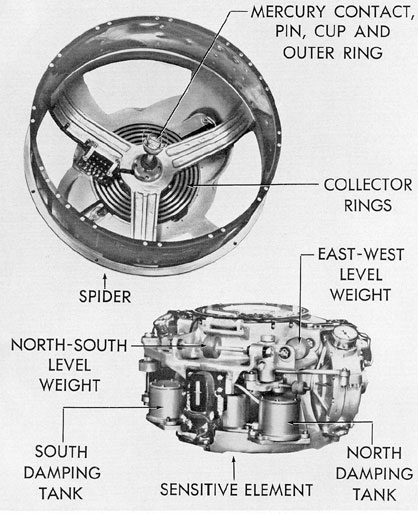
17E4. Spider and bowl. The compass frame
consists of a large bowl suspended from the
inner gimbal ring by 16 helical springs, and a
spider attached to the upper surface of the bowl.
(See Figure 17-25.) The supporting springs are
divided into 8 sets of 2 springs each. This
construction allows freedom of the suspended parts
in the horizontal plane and yet exerts a centering
effect when the frame has been displaced
from its normal position. Small metal damping
tubes inserted in the springs damp out any
oscillations of the frame.
The enclosure formed by the bowl on the
bottom is completed on top by the spider which
is fitted with 4 removable transparent covers.
The spider provides a mounting for the speed-course
correction mechanism and supports the
transmitter assembly, follow-up motor, and
follow-up coil. To the top of the spider is fastened
the follow-up motor and transmitter support
casting which in turn carries the driving
arm support.
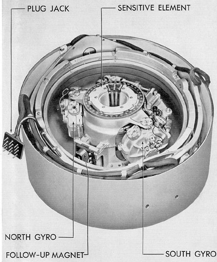
17E5. Sensitive element. The north-seeking
portion of the master compass is the sensitive
element; (See Figures 17-27 and 17-28.) This unit
through gyroscopic action and by virtue of the
earth's rotation tends to keep its axis in the
meridian. By means of the follow-up system and
235
Figure 17-26. Diagrammatiic drawing of master compass.
transmitter, the position of the element controls
the reading of repeater compasses throughout
the ship. Since the element must be extremely
free to turn about any axis, it is supported by
a steel ball which floats in mercury.
The sensitive element consists of a frame
on which are mounted 2 gyro units and an oil
damping device. Each gyro unit is free to rotate
about a vertical axis but the 2 units are
coupled together by a linkage. On the element
are 2 magnets for exciting the follow-up system,
and an emergency azimuth scale to be used if
the follow-up system should fail.
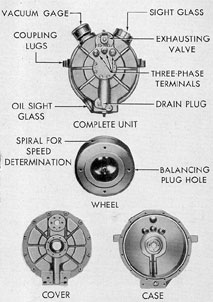
17E6. Gyro units. Two gyro units provide
directive force for the sensitive element; that is,
they turn it toward the meridian. One of these
units is shown in Figure 17-29.
The casing of each unit is equipped externally
with upper and lower spindles and ball
bearings so that it is free to rotate about a
vertical axis. Around the sight glasses, and other
joints, neoprene gaskets are used to make the
case airtight.
The gyro wheel and its axle are machined
in one piece from alloy steel. Each end of the
axle is accurately fitted with ball bearings which
are supported inside the gastight casing. One
side of the gyro wheel is machined out around
the axle to make room for the induction motor
windings. The squirrel cage winding is pressed
into the gyro wheel. The primary, or stator,
projects into the center of the rotor squirrel
cage. Leads from the stator are carried through
the casing to terminals on the outside for connections
to the supply line. Around the periphery of the
wheel a spiral groove is turned and
enameled black. This groove is observed through
a sight glass on the case to determine whether
or not the wheel is rotating in the correct
direction when it is started.
The lubrication system consists of an oil
sump at the bottom of the casing from which
236
Figure 17-27. Arma master compass, cover and spider removed to show sensitive element.
237
Figure 17-28. Bottom view of spider, sensitive element.
238
Figure 17-29. Gyro unit, disassembled.
cotton wicks carry the oil up and around each
of the axle ball bearings. The oil sump is
provided with a drain plug end with a circular
sight glass to show the oil level, the correct level
being at the midpoint of the glass. A high-grade
oil that is free from moisture and other volatile
substances is used.
A vacuum is maintained within the case to
eliminate windage losses, to reduce the heating
of the rotor, and to prevent gumming of oil in
the bearings. A gage on the unit shows the degree
of vacuum and so serves to indicate possible leakage.
The casing is fitted with an exhaust
valve that is used in evacuating the case. On
the north gyro unit, the positions of the vacuum
gage and sight glasses are opposite to what they
are on the south gyro. Therefore the units are
not interchangeable.
17E7. Oil damping system. On the east side
of the sensitive element frame are 2 tanks partly
filled with oil and connected at the bottom by a
pipe. (See Figure 17-30.) Were it not for this
damping system, the element would continually
oscillate back and forth across the meridian
instead of settling down into its correct position.
The illustration shows the tanks in a sectional
view. They are aligned parallel to the meridian
and are totally enclosed. The tanks are connected
by a pipeline at the bottom for oil, and
by another at the top for air. They are filled
to a depth of 1 1/4 in.
In order to obtain the proper damping percentage,
it is necessary to restrict the flow of oil
between the tanks. This is accomplished by
means of an obstruction inserted in the pipeline.
To avoid the damping error, it is necessary
to nullify the effect of the damping system during
changes in course. To prevent the flow of
oil due to the accelerating forces present during
a turn, a damping cutout valve is placed in the
oil line connecting the two damping tanks. This
valve operates whenever the change in ship's
course is greater than 15 degrees and it is
controlled automatically by a pair of contacts in
the transmitter assembly. The valve consists of
a steel ball, inside the oil line, which can be
drawn up vertically against a spherical seat by
an external electromagnet when the oil flow is
stopped. Thus, the valve is operated without
disturbing the equilibrium of the sensitive element.
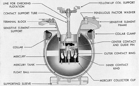
17E8. Mercury flotation. The directive force
of any gyrocompass is small when nearly on the
meridian. It is therefore necessary to suspend it
in as nearly a frictionless support as possible.
This is accomplished by supporting the sensitive
element on a hollow steel sphere which floats in
a concentric tank of mercury (see Figure 17-31).
The element is constrained from drifting
laterally by the center electrical contact pin
which fits loosely into a guide at the center of
the floating sphere. This pin, together with a
pair of concentric contact rings, projects from
a shaft which is carried at the center of rotation
of the follow-up arms. Thus, there is practically
no relative rotation between the contact pin and
rings and the sensitive element. The vertical
position of the element is governed by the
239
quantity of mercury in the tank. The sphere should
clear the bottom of the tank by 3/16 in. For
convenience in checking this position, a line has
been placed on the contact support tube. This
line is level with the topmost surface of the
sensitive element when the flotation is correct.
17E9. Oscillation mechanism. To eliminate
any possible static friction in the mercury
17E10. Follow-up mechanism. a. General.
The follow-up mechanism is that part of the
master compass that drives the card dials and
controls the repeater compass readings without
reacting upon the sensitive element. This is
accomplished by amplifying a small voltage which
is induced in the follow-up coils by magnets on
the sensitive element, and using this amplified
Figure 17-30. Oil damping system.
which would slightly reduce the freedom of the
sensitive element, the tank is suspended from
leaf springs and caused to oscillate continuously
through a small angle several times a second.
The oscillating mechanism is located below the
tank. (See Figure 17-26.) The mechanism consists
of a split-phase motor driving an eccentric
and connecting linkage.
voltage to control a motor geared to the card
and follow-up coil. The motor operates to keep
the follow-up coil and the card in their proper
position relative to the sensitive element. The
follow-up mechanism is part of the master compass.
It is distinguished from the follow-up system that
includes the mechanism and the follow-up panel.
240
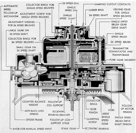
b. Speed correction mechanism. The automatic
speed correction mechanism is provided
with a synchronous motor which receives an
indication of ship's speed from the underwater
introduced into the multiplier, and the resulting
product is applied to an eccentric bearing in the
correction mechanism. The speed corrector requires
manual resetting only for changes in
Figure 17-31. Flotation and contact assembly.
log, and a follow-up motor which applies this
quantity to a lever type multiplier. By means of
a manual control which is graduated in degrees
of latitude, the secant of the latitude is
latitude; speed variations are taken care of
automatically. Provisions are made for hand setting
of the ship's speed when the underwater log is
secured.
241
Figure 17-32. Automatic speed correction and driving mechanism.
242
Figure 17-33. Spider assembly.
F. MOTOR GENERATOR
17F1. Function. The motor generator set
converts the ship's direct current power supply
to a 3-phase supply of variable frequency for
driving the gyro wheels.
17F2. Construction. The motor and generator
are enclosed in a drip-proof housing. Their
rotors are on a shaft which is supported at the
frame ends on ball bearings, each bearing being
lubricated by a grease cup. The generator is
driven by a compound-wound direct-current
motor, rated at 115 volts, 3.0 amperes, and 3,000
rpm. Speed control is obtained by means of an
external rheostat in the motor field circuit. The
motor has been specially designed for good speed
regulation so that the effect of variations of the
supply voltage on the motor speed has been reduced
to a minimum.
Motor generator sets supplied with the various
modifications of the master compass are
similar in external appearance but vary slightly
in capacity. The Mark X Mod. 2, generator is
rated at 67.5 volts, 2.0 amperes, and 300 cycles
at 3,000 rpm.
When the motor speed is reduced, the generator
voltage and frequency are correspondingly
reduced. Direct current required to excite the
generator field is obtained through the control
panel from the ship's supply.
G. CONTROL PANEL
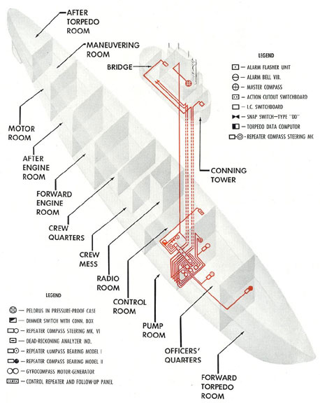
17G1. General. Figure 17-34 shows the repeater,
control, and follow-up panels. The control panel
is used for controlling the operation
of the master compass and for indicating conditions
of operation such as current and voltage
values.
243
Figure 17-34. Schematic diagram of gyrocompass system.
244
Connection to motor generators, master
compass, and other equipment is made through
this panel.
17G2. Instruments. At the top of the control
panel are 2 ammeters, 2 voltmeters, and a
neon indicator lamp. The lamp serves as an
indicator for the damping cutout and operates
when the oil flow system between the damping
tanks has been cut off. The 4 instruments indicate:
1. The gyro drive current in each phase.
2. The current drawn by the repeater system.
3. The d.c. supply voltage.
4. The gyro variable frequency supply
voltage and the 60-cycle, single phase a.c.
supply voltage.
17G3. Repeaters. Outgoing circuits are provided
on late fleet type submarines to repeaters
located as follows:
1. forward torpedo room-1 speed
2. commanding officer's stateroom-1 speed
3. control room steering station - double
dial, concentric 1 and 36 speed
5. bridge pelorus-double dial, concentric
1 and 36 speed with illuminated relative
bearing ring
H. OPERATION
17H1. General. The gyrocompass is a
sensitive instrument. The first essential
in its operation is to see that it is
operated by trained personnel only. No
attempt should ever be made
to disassemble or adjust it. Only qualified
gyrocompass repair personnel should ever attempt a
major repair or adjustment.
17H2. Starting the master compass. The
following procedure should be followed in
starting the master compass:
1. The compass should be started about 4
hours before it is required for service.
2. Check the vacuum gage reading of the
north and south gyro units. The vacuum should
be approximately 29 inches.
3. Check the oil level in the gyro case. The
level should be approximately halfway up the
sight glass at the bottom of the case. This check
may be easily made by holding a mirror next
to the sight glass and viewing the reflection of
the oil level in the mirror.
4. See that all switches on the control and
repeater panel are in the OFF position. The
damping cutout switch is an exception to this
rule and should be in the ON position when the
ship is not making way.
5. Have the power supplies to the control
panel energized.
6. Start the compass and check its
operation as described in the manufacturer's
instruction book.
7. Read the gyro current in each phase every
hour. The current should be about 1.25 to 2.25
amperes. An abnormally high current indicates
trouble which should be investigated immediately.
8. Read all voltages and currents every
hour. Normal values are as follows:
Gyro drive
1.25 to 2.25 amperes
A.C. single phase
115 volts
A.C. gyro drive voltage
23-68 volts
D.C. voltage
115 volts
Repeater system current
See below
The instrument marked REPEATER SYSTEM
CURRENT indicates the current drawn
by the transmitter circuit and repeaters. It will
read about 5 to 6 amperes when no repeaters
are connected. The reading should increase
about 0.6 amperes for each additional
synchronous motor added to the load.
17H3. Use of level in settling element or
meridian. If it is necessary to put the compass
in operation on short notice, considerable time
may be saved by precessing the element on to
the meridian by hand. Proceed as follows:
245
1. Start the compass in the usual manner.
2. Determine the approximate ship's heading.
3. Precess the element until the card indicates
the ship's heading. This is done by pressing down
lightly on the north or south side of
the element.
4. Bring the bubble in the north-south
level to the center of the scale. To do this press
against the end of the bubble tube in the direction the bubble must go.
5. It is impractical to set the compass and
have it remain exactly in its settled position
because the damping oil must seek its final level
and because temperature changes as the instrument
warms up cause slight disturbances.
17H4. Shutting down the compass. To stop
the compass, turn all the switches on the control
and repeater panels to the OFF Position.
No further attention is required. The gyro
wheels will continue to rotate for about an hour.
Do not attempt any work on the element until
the wheels have stopped.
I. CARE AND MAINTENANCE
17I1. Inspection and checks. The gyrocompass
requires little attention if operating instructions
are carefully followed. Inspection, cleaning,
and oiling should be done regularly in
accordance with the schedule below. Visual
inspection may, of course, be made at any time,
but as long as the compass is operating satisfactorily,
it is best not to perform the other
checks more often than indicated by the schedule.
Never shift a weight or make any other adjustment
until it is definitely known that trouble
exists, and until that trouble has been analyzed.
17I2. Maintenance schedule.
1. Every hour. Check the gyro current and voltages.
2. Every watch. Inspect the vacuum
tubes. Make immediate replacement of defective
tubes.
3. Once a week. Check the vacuum gage
readings. Small changes from previous readings
may be due to variations in barometric pressure,
but a large change indicates trouble.
Clean the control and repeater panels. Inspect
the connections and look for blown fuses.
Clean the motor generator set. Turn down
each grease, cup one turn.
4. Once a month. Clean the binnacle
inside and out, making certain that no foreign
objects have fallen across the terminal blocks
in the base.
Clean the bowl and spider.
When the gyro wheels are not rotating, clean
the entire sensitive element.
5. Once in 3 months. Put a drop of gyro
oil in each gimbal ring bearing.
6. Twice a year. Check the depth of oil
in the damping tanks. This should be from 1 1/8
to 1 1/4 inches average value in the 2 tanks. The
depth in each tank may be measured by removing the
cover. If the average depth is low, add
clean oil to bring it to the correct value. Be
very careful to keep out dirt, or any foreign
particles.
7. Once every 24 months. Lubricate the
synchro bearings if they have not been
lubricated in the previous 18 months. Use
1 drop of oil in each bearing.
The upper spider bearings and all gearing
should also be lubricated every 24 months,
although this is not absolutely necessary.
8. After extended shutdown. Before starting
the compass after it has been out of service
for some time, all the checks that are made once
in 3 months or more often should be gone over.
In addition, the transmitter commutator, all
collector rings, and the damping cutout contact
should be examined and, if necessary, wiped off
with a cloth dampened with an approved solvent.
17I3. Compartment pressure test. Before
any compartment of the ship is submitted to a
15-pound pressure test, all repeater compasses
in the compartment must have the small plug
in the lower cover removed to equalize the pressure
on the glass. A master compass in the compartment
must have the vacuum cocks of both
gyro casings opened to equalize the pressure on
the casings and to protect the vacuum gages
from breakage.
246
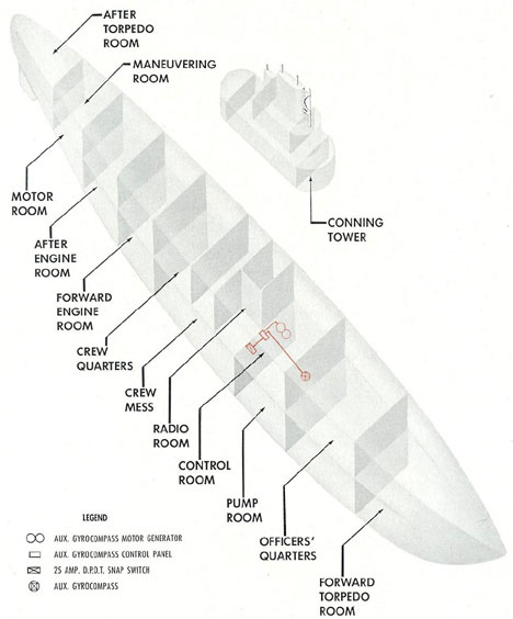
Figure 17-35. Schematic diagram of auxiliary gyrocompass system.
247
J. AUXILIARY GYROCOMPASS
17J1. Description. a. General. The Arma
Mark 9 gyrocompass has been developed as an
auxiliary compass for submarines, to indicate
accurately the ship's true heading. It is designed
primarily for emergency use when the main compass
is inoperative. The auxiliary compass is
light, compact, simple to operate, and readily
accessible for maintenance.
The equipment consists of 3 main units, the
compass proper, which is enclosed in a binnacle,
the motor generator, and the control panel.
b. Compass unit. The compass unit houses
the north-seeking sensitive element, which has
gyros arranged in such a manner that the rotation
of the earth tends to maintain the element
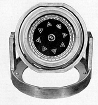
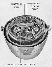
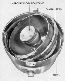
Figure 17-36. Arma auxiliary gyrocompass Mark 9, cover removed.
on the meridian. The sensitive element floats
freely in a tank of mercury and carries 2 gyros
mounted at an angle of 25 degrees to the meridian.
Two wheels are used to stabilize the sensitive
element in an east-west direction, thereby
eliminating the intercardinal rolling error. The
gyros run at about 18,000 rpm and are supplied
with power from a motor generator, driven by
the ship's supply. A pair of oil-filled damping
tanks, connected by a restricted pipe, are also
mounted on the element, level with the center
of flotation, so that tilting of the element of
gimbal rings will not cause an apparent change
in course. The dial is read through the binnacle
cover glass. The element is restrained from drifting
sidewise in the mercury by means of a centering
stalk, which also provides an almost frictionless
method of making an electrical connection to the
gyros. The other connection is made
through the flotation mercury. The mercury
tank is oscillated back and forth through a small
angle, several times a second, in order to break
up surface friction between the mercury and the
pot. The entire inner member containing the pot
is pendulous and is spring-mounted in a pair of
gimbals. The gimbal pivots are damped by
means of felt washers saturated with an
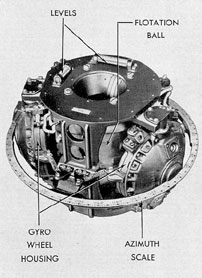
Figure 17-37. Arma auxiliary gyrocompass Mark 9, sensitive element.
248
extremely viscous oil. Access to the sensitive element
is obtained by removing the top portion
of the binnacle and the bridge cover over the
element.
Figure 17-38. Arma auxiliary gyrocompass Mark 9,
lower housing, gimbals and mercury flotation tank.
The gyro wheels are driven by squirrel cage,
induction motors, whose high frequency supply
is furnished by the motor generator. The single
phase output of the generator is made 2-phase
in effect, by running one side of the line through
a condenser network to split the phase. The
starting load on the gyro rotors is naturally
much higher than the running load. To keep
the phase relationship correct for both conditions,
one of the condensers is cut out of the
circuit when the wheels are nearly up to their
normal speed. This is accomplished by a thermal
relay mounted on the sensitive element.
When the thermal relay is cold, its contacts are
open. Its heating element is connected in series
with one winding of the gyro motors, and consequently
is subjected to the current drawn by
the gyros. The relay contacts are adjusted to
open when the wheels are about up to speed,
which requires approximately 10 minutes.
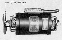
c. Motor generator. The motor generator
(Figure 17-39) is designed to operate from 115
volts, d.c., and run at about 3,000 rpm. There
are 2 generators in the unit. One, a 120-volt,
300-cycle, single-phase generator is for the gyro
supply; the other, a 24-volt, d.c. generator is
for operating the oscillator motor and compass
lights.
Figure 17-39. Arma auxiliary gyrocompass Mark 9
motor generator set with end covers removed.
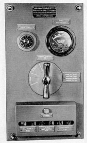
d. Control panel. (See Figure 17-40.)
One type of control panel is used where the
compass power supply is between the limits of
88 to 125 volts d.c. This condition exists on
ships in which the compass is run from the 88-
to 125-volt lighting bus, which normally is
controlled to 115 volts d.c. On other vessels using
this panel, the compass normally is supplied
from the 115-volt lighting motor generator, with
an auxiliary supply from the 88- to 125-volt tap
on the main battery, controlled to 115 volts.
Here, both normal and auxiliary supplies come
over the same leads from the I.C. switchboard.
A green pilot lamp is provided to show when
the power supply is available.
To insure positive starting of the motor
generator, in case the voltage is allowed to drop
to 88, a START position is provided on the
motor generator switch. In this position, a
249
resistance is placed in series with the field of the
motor, which is the shunt-wound type, and resistance
is cut out of the generator field circuit.
This gives sufficient speed and output voltage
to start the gyros. The switch should be left in
this position for 3 minutes, before being thrown
to ON. The compass operates best when the
supply voltage is kept within 10 percent of 115
volts.
17J2. Operation. In general, the operating
procedures for the auxiliary compass are the
same as for the main compass. Detailed
instructions may be found in the manufacturer's
instruction book.
17J3. Maintenance. Complete instructions
for the maintenance of this compass are given
in the manufacturer's instruction book which
should be consulted prior to servicing the compass.
Figure 17-40. Arma auxiliary gyrocompass Mark 9
control panel.
K. DEAD RECKONING ANALYZING INDICATOR AND TRACER SYSTEMS
17K1. General. The Arma dead reckoning
system consists of a Mark 5 Mod. 0 dead
reckoning analyzer indicator located in the control
room, and a Mark 7 Mod. 1 dead reckoning
tracer located in the control room, or in some
ships, in the conning tower.
The system, when properly set at the starting
point, indicates at all times the latitude and
longitude of the ship's position on dials visible
through windows in the cover of the analyzer
indicator, and traces the ship's movements on a
chart placed on the tracer. The total distance
traveled by the ship, regardless of its course, is
also indicated on the analyzer.
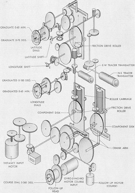
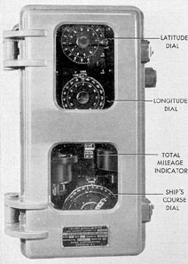
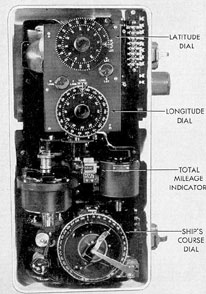
17K2. Analyzer indicator. The analyzer indicator
(Figures 17-41, 17-42, and 17-43) is an
instrument for converting the ship's course and
distance into direct readings of latitude, longitude,
and miles traveled. It receives the ship's
course from the gyrocompass, and its distance,
from the underwater log system. In some units,
2 transmitters have been installed in the analyzer
indicator for transmitting distance and
direction of ship's movement to the dead reckoning
tracer motors which drive a pencil over a
chart.
17K3. Distance converter. The distance converter
is comprised of the distance input motor,
energized by the underwater log distance transmitter,
and the gearing that connects the motor
to the component carriages.
These carriages are mounted in guide rollers to
permit vertical motion which determines
the position of a friction disk and consequently
the speed of the gear train.
Crank arms, controlled by the input from
the gyrocompass, position the carriages vertically.
By their movement, the ship's travel,
through the rotation of 2 disks, is resolved into
250
components in a north-south and east-west
direction. Through an arrangement of gears and
disks, the motions of the disks are transmitted
to longitude and latitude dials and drive the
dead reckoning tracer transmitters. Arrangement
is made for shifting the latitude mechanism for
either north or south operation when
the equator is crossed. Likewise, the longitude
mechanism must be shifted when crossing 0 or
180 degrees longitude.
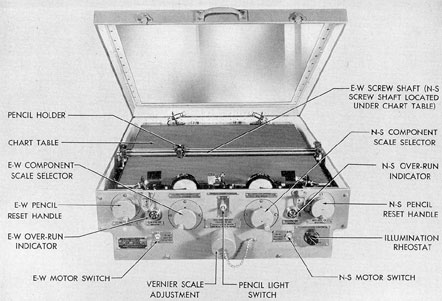
17K4. Dead reckoning tracer. The tracer is
enclosed in a metal box with hinged glass cover
(Figure 17-44). The principal parts of the tracer
mechanism include the cross screw motor which
drives the tracing pencil in an east-west direction
across the chart by rotating the cross screw.
The north-south motion of the pencil is derived
from the lead screw motor which, through a
screw shaft and nut, moves the cross screw,
pencil, and support arms in a north-south direction.
To permit the use of the tracer on differently scaled
charts, the speed of the cross screw
and lead screw can be regulated by means of
the friction disks between the drive motors and
screw shafts. This setting is made by turning
the handwheels to the scale of the chart being
used. These handwheels are located outside the
tracer box and are designated as scale selectors.
Switches are provided to stop and start the
screw motors. Illumination is controlled by
means of a rheostat. Pilot lamps indicate when
the mechanism has reached the end of the screw
shafts. The initial starting point of the pencil is
set by means of hand cranks.
251
Figure 17-41. Dead reckoning analyzer Indicator gear diagram.
252
Figure 17-42. Dead reckoning analyzer indicator.
Figure 17-43. Dead reckoning analyzer Indicator with
cover open.
Figure 17-44. Dead reckoning tracer with cover raised.