16A1. General. The general announcing system
provides a means of broadcasting orders
and information by voice from any one of 3
stations, bridge, conning tower, and control
room, simultaneously to all compartments of
the submarine. The submarine control announcing
system provides a means of 2-way loud-speaking
voice communication between the
bridge, conning tower, and control room, and
between these stations, the 2 torpedo rooms and
the maneuvering room. It is principally designed for
the rapid interchange of orders, acknowledgments and
information between the
above stations in combat, and for this purpose
may be regarded as part of the fire control system.
The general announcing and the submarine
control announcing systems are interconnected
and utilize the same equipment.
Three alarm systems having distinctive
tones and known as the general alarm, collision
alarm, and diving alarm are incorporated in, and
are a part of, the general announcing system.
The general alarm, a single stroke repeated gong
sound, calls all hands to their stations for battle
and is used as an alarm for fire. The collision
alarm, the sound of a motor siren, is the signal
that collision is imminent or has occurred and
is the order to rig the ship to minimize and
localize the damage. The diving alarm is the
sound of a motor-driven horn and is the signal
to submerge the ship or to surface if submerged.
Due to its importance, this system is paralleled
by a set of motor-driven horns installed in certain
key stations, which operate independently
of the electronically produced signals in the
general announcing system. They are provided
so that the diving signal can be given even when
the general announcing system has failed.
B. GENERAL ANNOUNCING SYSTEM
16B1. Description. Equipment for the late
fleet type general announcing system is manufactured
by the Victor Division of the Radio
Corporation of America. A detailed description
of the equipment is given in the instruction book
provided by the manufacturer.
Power is supplied from the 120-volt alternating
current bus on the I.C. switchboard
through a double pole, single throw, fused
switch. Circuit 1MC is provided for the general
announcing system and circuit 7MC is provided
for the submarine control announcing system.
Circuit 7MC is closely tied in with circuit 1MC.
This same amplifier equipment is also used
for the 7MC circuit. Normally, one channel is
set up for use on the 1MC circuit and one channel
for use on the 7MC circuit, but switches are
provided so that in an emergency both circuits
may be operated through either of the 2 individual
amplifier channels.
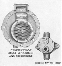
Figure 16-2. General announcing bridge units, switch
box and bridge reproducer and microphone.
211
16B2. Components. The system consists of
the following components:
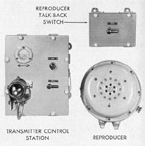
1. The transmitter control station, which
contains a microphone, control switches, a
volume indicator, and a socket into which a portable microphone may be plugged. There are 2
of these stations, one in the conning tower and
another in the control room.
2. The signal generator, which produces
the audio frequency signals that are broadcast
over all reproducers for alarm signals. There are
2 signal generators located in a common housing
in the 1MC stack in the control room.
3. The amplifier, which raises the energy
level of the input voice or alarm signal high
enough to operate the reproducers with adequate
volume. There are two 120-watt amplifiers built
into the 1MC stack; they are designated as
channel A and channel B.
4. The reproducer, which converts the
electrical output of the amplifier into sound
waves; with proper connections, such as those
available at the bridge reproducers, they can
also be used as microphones. There are 19 reproducers
installed for use on the 1MC circuit.
The number installed in each location is shown
in the table at the bottom of the page.
Supplementing the reproducers are 11 type
H-9 horns which are operated by the diving
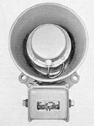
Figure 16-3. General announcing reproducer, class H.
Figure 16-4. General announcing system showing
reproducer talk-back switch, reproducer, and
transmitter control station.
alarm. Two of these horns are located in the
forward engine room, 2 in the after engine room,
and one horn in each of the following locations
forward torpedo room, officers' quarters, control
room, crew's mess, crew's quarters, maneuvering
room, and after torpedo room.
An overhead fixture, non-watertight, with a
green globe, is connected in parallel with the
type H horns in each engine room for a visual
signal.
The reproducers on the bridge can be used
either on circuit 1MC or 7MC. When it is desired
to talk over circuit 7MC, it is necessary
only to speak into the reproducer. If it is desired
to talk over circuit 1MC, the pressure-proof
switch located near the reproducer must
be held down.
The reproducers on the bridge can be cut
out by a switch labeled BRG. 1MC-7MC at the
control panel on the amplifier. The water pressure from submerging also cuts out these reproducers.
LOCATION
NO.
LOCATION
NO.
Forward Torpedo Room
2
Crew's Mess
1
Officers' Quarters
1
Crew's Quarters
1
Control Room
1
Forward Engine Room
3
Bridge
2
After Engine Room
3
Conning Tower
1
Maneuvering Room
1
Radio Room
1
After Torpedo Room
2
212
16B3. Operation. This system provides one-way
voice communication from the bridge, conning
tower, and control room to all compartments
and also provides the means for generating,
amplifying, and reproducing the general
alarm, or gong signal, the diving alarm, or horn
signal, and the collision alarm, or siren signal,
in all compartments. The general alarm takes
precedence over voice communication. The diving
alarm takes precedence over general alarm
and voice, and the collision alarm takes precedence
over all other uses of the IMC circuit.
C. SUBMARINE CONTROL ANNOUNCING SYSTEM
16C1. Description. This circuit, known as
the 7MC circuit, is closely tied in with circuit
1MC. (See description of circuit 1MC in the
preceding sections,)
16C2. Operation. Circuit 7MC provides
two-way voice communication between the
bridge, conning tower, control room, forward
torpedo room, after torpedo room, and
maneuvering room.
On this circuit, all reproducers can be used
as microphones by pressing the TALK switch.
In the normal position the bridge reproducers
are connected for TALK and all other reproducers
for LISTEN. Closure of the TALK
switch at any other location connects that
reproducer to the input of the amplifier for use
as a microphone and transfers the bridge reproducers
to LISTEN.
16C3. Older installations. Many of the
earlier fleet type submarines were equipped with
the 1MC system only, with microphone transmitter
stations on the bridge and in the conning tower
and control room and with provisions for use of
throat microphones at the forward and after torpedo
tube nests if desired.
Intercommunication by voice between the
bridge, conning tower, control room, torpedo
rooms, and in some installations, the maneuvering
room, was provided by means of a conventional
interoffice type of loudspeaking system.
The 1MC systems in these submarines did not
incorporate the electronic signal generators for
the alarm systems but were equipped with the
auxiliary horns for the diving alarm system.
The general alarm and collision notes were produced
by picking up by microphones, and amplifying the
sounds produced by an electric
gong and an electric siren located in the control
room, and transmitting these sounds over the
1MC system.
D. GENERAL ALARM SYSTEM
16D1. Description. Late fleet type submarines
use 2 manual contact makers which are installed
in the control room and in the conning tower.
The latter is connected through a double pole,
single throw, unfused cutout switch on the I.C.
switchboard to the 1MC system. The general
alarm circuit designation is G.
16D2. Operation. Operation of either contact maker
energizes a circuit in the 1MC
system which takes
precedence over voice inputs
to the 1MC system but is subservient to inputs
either from circuit CA or circuit GD. This circuit
causes the signal generator in the 1MC system to
generate a gong sound which will continue
automatically at a rate of about 100
strokes per minute for a period of 10 seconds,
and is sounded over all loudspeakers of the 1MC
system.
E. COLLISION ALARM SYSTEM
16E1. Description. Three manual contact
makers are installed, one in the control room,
one in the conning tower, and a third on the
bridge. The latter two are connected through
separate double pole, single throw, unfused
cutout switches on the I.C. switchboard to the
1MC system. The collision alarm circuit designation
is CA.
16E2. Operation. Operation of any contact
maker energizes a circuit in the 1MC system
that takes precedence over all other circuits
using the 1MC system and produces electronically
a siren signal which is sounded over all
the 1MC loudspeakers.
213
F. DIVING ALARM SYSTEM
16F1. Description. Three manual contact
makers are installed: one in the control room,
one in the conning tower, and the third on the
bridge. The latter two are connected through
except the CA circuit, to which it is subservient.
This circuit causes the signal generator of the
1MC system to generate electronically the sound
of a klaxon horn which is sounded over all
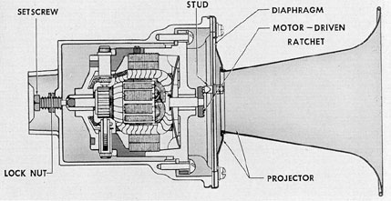
Figure 16-5. Motor-operated horn, type H-9.
separate double pole, single throw unfused cutout
switches on the I.C. switchboard to the 1MC system.
The diving alarm circuit designation is GD.
16F2. Operation. Operation of any contact
maker energizes a circuit that takes precedence
over all other circuits using the 1MC system
loudspeakers of the 1MC system. Simultaneously, a
relay operates to energize auxiliary H-9
horns located in each compartment having a
1MC loudspeaker except the bridge, conning
tower, and radio room, which are not equipped
with H-9 horns.
G. COMMUNICATION AND ALARM SYSTEM MAINTENANCE
16G1. General maintenance. All components of the
system should be subjected to a
routine inspection. This inspection should cover
an examination of relay contact and switch action
and in case of the amplifier, plate readings
should be checked by means of the test buttons
and jack with the circuit analyzer.
Relay contacts should be periodically
cleaned. This is easily done by running a piece
of bond paper between the contacts, holding the
relay manually in such a position that the contacts
are closed on the paper.
Inspection of a routine nature should also
cover the removal of accumulated dust and dirt
from the amplifier cabinet and other apparatus
being inspected. A bellows blower is convenient
for the removal of dust from the amplifier cabinet
and the relay panels.
Units other than the amplifier should be
checked for electrical connections and loose
mechanical parts such as mounting bolts and similar
items.
A thorough and frequent routine inspection
will, in many cases, prevent subsequent system
failure. Any parts that are in doubtful operating
condition should be readjusted or replaced.
The manufacturer's instruction book should
be consulted for complete details of maintenance,
construction, and operation.
214
H. SOUND-POWERED TELEPHONE SYSTEM AND
TELEPHONE CALL CIRCUITS
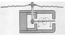
16H1. Description of sound-powered telephone. A
sound-powered telephone is a telephone system in
which the power comes from
the sound of the voice rather than from batteries.
Vibrations from the voice cause vibration
of a diaphragm in the transmitter. Attached to
the inside of the diaphragm is a delicate needle
called the armature. Surrounding this armature
is a coil of fine wire, held in place by a magnet.
Every time the diaphragm vibrates from the
sound of the voice, the armature also moves
inside the coil. This induces a current in the
coil which passes through the line to a receiver.
Internally, the receiver is constructed exactly
like the transmitter. Thus, the current from the
transmitter passes through the coil in the receiver
causing its diaphragm to vibrate and reproduce the
speaker's voice.
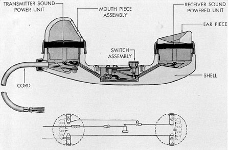
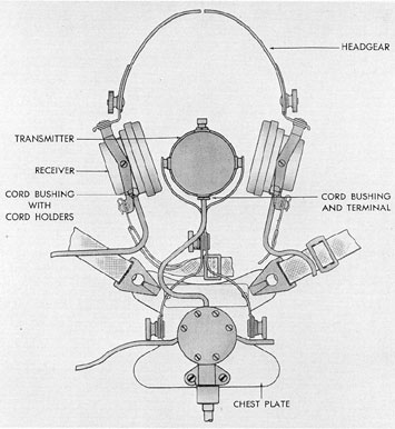
This type of telephone is supplied in both
the conventional handset form and the headset
type which consists of a headset and a separate
transmitter mounted on a breastplate and supported
by a neckstrap.
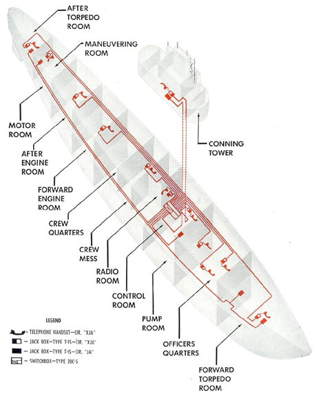
16H2. Circuits and stations, battle telephone system. The telephone system is divided into 2 circuits, the XJA (handset) used
for routine ship's service communication, and
the JA (headset) used on all battle control stations.
The installations vary on different ships.
The following is a description of a recent fleet
type installation.
There are 2 independent JA circuits with 8
stations. One circuit runs from the spotter's
position on the No. 2 periscope support to a
headset receptacle at the 4-inch gun. This circuit has no interconnection with any other circuit. The other JA circuit has 5 lines running
from the switch box in the control room to jack
boxes located as follows: forward torpedo room
(2 outlets in 1 circuit), control room, conning
tower, maneuvering room, and after torpedo
room. Each station may be independently cut
out by means of toggle switches in the switch
box in the control room.
Each station consists of a jack box into
which a headset can be plugged. The box is
equipped with a luminous disk marked with the
identifying letters of the circuits.
Headsets are stowed in lockers near the jack
boxes in the forward and after torpedo rooms
and maneuvering room, on stowage hooks in the
control room, and in the chart table in the
conning tower.
The XJA system consists of 12 circuits running
from the same switch box in the control
room which also serve the JA system. The
circuits connect to stations located as follows:
1.
forward torpedo room
2.
wardroom
3.
captain's stateroom
4.
forward battery space
5.
control room
6.
conning tower
7.
radio room
8.
crew's mess
9.
forward engine room
10.
after engine room
11.
maneuvering room
12.
after torpedo room
Each station consists of a jack box with a
type L handset wired into it and held in a
shockproof clip. A headset can also be plugged
into any jack box if desired.
The switch box is located between the periscope
walls in the control room, and facing to
starboard has 20 toggle switches. Twelve of the
switches in the 3 left-hand vertical rows serve
the circuits of the XJA system, and 5 in the 2
right-hand vertical rows serve the JA system.
The other 3 switches are spares.
16H3. Telephone switchboard.The telephone
switchboard is made up of several small
single throw, double pole switches. Each pair of
telephone leads to each handset and each headset
is connected to its own switch on the switch
board.
215
Figure 16-6. Schematic diagram of sound-powered telephone system.
216
Figure 16-7. Sound-powered telephone diaphragm and
armature.
One of the 2 sets of bus bars on the back of
the switchboard makes up the JA bus, the other
the XJA bus. Switches connect the respective
JA and XJA phones to their respective buses.
Thus, the JA and XJA circuits are common talking
bus circuits and only one conversation can
take place at a time over each bus.
Provisions are made to cross-connect the
XJA and JA bus by means of either a crossconnect
switch on some boards, or by means of
a patching cord. The patching cord is a plain,
2-conductor, rubber-covered cable about 3 feet
long with a jack plug on either end.
Each switch on this type of board has a
jack connected to it. To cross-connect with the
patching cord, plug one end of it into any JA
switch and the other end into any XJA switch.
Normally all switches are in the CLOSED position.
The patching cord thus connects the JA
and XJA bus together in the same way as the
cross-connect switch previously mentioned. Any
two phones can also be connected together by
patching cords.
CAUTION. As previously described, the
voice causes the transmission voltage to be
generated in the units. Neither the telephone
switch-board nor the telephone circuits are
connected
in any way to an outside source of electrical
power. Never plug in or connect any part of the
telephone switchboard or any headset or handset
to any light or power connection as this will
burn out the coils of the units.
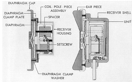
Figure 16-8. Sectional view and wiring diagram of sound-powered telephone handset.
217
Figure 16-9. Headset sound-powered telephone.
16H4. Operation. it should be noted that the headset
as well as the handset is made of
delicate parts and must therefore be worn in
the correct position, used carefully, and properly
stowed. Telephones that are out of order may
prevent other telephones on the circuit from
working properly.
In the event of a casualty to the transmitter
on the headset telephone, it is possible to speak
into one earpiece while listening through the
other. In the event of casualty to the earphones
on a headset, hold the transmitter button down
and receive and transmit with the transmitter.
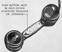
With the headset telephone, push the
button only when speaking; it is not necessary to
push the button while listening. With the headset
telephone, the button is held down when
speaking and listening. It is a bad practice to
keep the button taped down or held down by a
rubber band as this will permit outside noise to
get into the circuit. All the power required for
operation is generated by the voice; no other source
of power is needed; hence, it is necessary
to speak loudly and clearly in order to supply the
necessary power.
16H5. Maintenance. The equipment must
always be handled carefully. Time after time,
this equipment has been the only means of
communication remaining between various parts
of the submarine when other sources had
218
Figure 16-10. Headset wiring diagram.
become inoperative due to power failure during
combat. Constant exposure to moisture will
Figure 16-12. Ship's service handset telephone.
harm the instruments. Keep them as dry as
possible at all times.
Rubber cables should be inspected frequently
and renewed when they show excessive
wear. Some of the wires in the system are very
fine and should therefore be handled carefully
to avoid breaking them.
Figure 16-11. Sectional view of receiver unit.
219
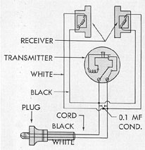
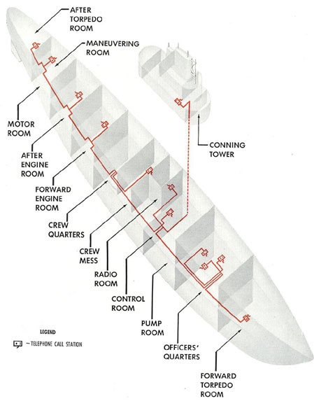
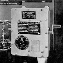
Figure 16-13. Schematic diagram of telephone call circuit.
220
I. TELEPHONE CALL CIRCUIT
16I1. Description. All call stations are connected
with TTHFA-15 cable (24 active conductors and 6 spares).
The cable to the conning
tower goes through a, cutout switch located on
the hull over the action cutout switchboard. The
call circuit letter marking is E. The system
consists of a rotary switch and a 115-volt bell
mounted at each handset station, and the connecting
cable. The rotary switch has a dial,
operated by the switch shaft, and marked to
show the various compartments and stations
with which the system connects.
Any station can be called from any other
station by setting the selector switch to the
station desired and then pressing the call lever.
This completes the circuit and operates the 115-volt
bell at the designated station or compartment.
The circuit is operated on either 115-volt
a.c. or d.c., depending upon the type of bell,
supplied from a switch on the I.C. switchboard.
Some later submarines are equipped with handcranked
signal generators and "howlers" at each
call station. Such a system requires no supply
voltage. It is a separate and complete circuit
and is in no way connected to the telephone
switchboard or to any part of the telephone
circuit.