3A1. Introduction. The main ballast tanks
are normally filled with sea water when the
submarine is submerged. These tanks cannot
be pumped; therefore, when the submarine is
surfacing, compressed air must be used to
blow the water out through the flood ports
to the sea.
Two separate systems are provided to
blow the main ballast tanks. This chapter
deals with the first of these, the 600-pound
MBT (main ballast tank) blowing system.
The second system, the 10-pound MBT blowing
system, is used only when the ship is
surfaced. It is discussed in Chapter 5.
Figure 3-1 shows the location of the lines
and component parts of the 600-pound MBT
blowing system. The system is inside the
pressure hull and extends from the MBT
blowing manifold in the control room fore
and aft along the starboard side to the main
ballast tanks and fuel ballast tanks.
The MBT blowing manifold, described
in Section 3B, is the distribution control unit
of the system. It is located on the starboard
side of the control room with its pressure
gage next to it. The piping mounted directly
above the manifold connects the MBT blowing
manifold with the high-pressure air manifold,
through two hammer valves.
The maximum working pressure of the
600-pound main ballast tank blowing system
is 600 psi. It is tested hydrostatically to a
pressure of 1000 psi, or 166 percent of the
maximum working pressure.
3A2. Hammer valves. Air at bank pressure
(1500 to 3000 psi) passes through two manually
operated hammer valves and two group
stop check valves to the 600-pound MBT blowing
manifold. The flow of the air is regulated
by the hammer valves so that it is delivered
at the required pressure. Normally only one
hammer valve is used for blowing; in case
the one does not supply enough air or in case
of failure, the other hammer valves can be
used. The group stop check valves permit the
blowing of tanks by groups. The manifold
is protected by a sentinel valve and two relief
valves (Figures 4-8 and 4-9) set to blow when
the pressure in the 600-pound system reaches
750 psi. The sentinel valve is set to blow at
a pressure of 610 psi. When the sentinel valve
opens, it acts as a relief valve for comparatively
small rises in pressure and gives notice
of excess pressure in the system.
To supply air to the 600-pound MBT
blowing system, one of the hammer valves is
opened. The valve permits air from the 3000
pound manifold to enter the MBT blow manifold
at a reduced pressure. The pressure gage
of the MBT blow manifold is closely watched,
to guard against the pressure exceeding 600
psi.
3A3. Operation. The depth at which the
submarine is operating will have a direct effect
on the resistance offered to the air in
blowing the main ballast tanks and therefore
will build up the pressure within the system
more rapidly at greater depths than it will
on the surface. Since the hammer valve
regulates the volume of air entering the 600-pound
MBT blowing system, while the resistance
offered to this air varies with submerged
depth, it follows that when submerged at
great depths, the hammer valve must be
opened cautiously, otherwise the pressure
within the system will build up rapidly and
exceed the safe working pressure. When the
gage indicates that the pressure is dropping,
the hammer valve is opened wider to maintain
the required pressure. When blowing
is finished, the hammer valve is shut.
Blow lines extend from the forward section
of the 600-pound MBT blow manifold
to tanks No. 1 MBT, Nos. 2B and 2D MBT,
Nos. 2A and 2C MBT, and Nos. 3A and 3B
FBT. From the after section of the manifold,
blow lines to tanks Nos. 4A and 4B FBT, Nos.
5A and 5B FBT, Nos. 6B and 6D MBT, Nos.
6A and 6C MBT, and No. 7 MBT. Any tank,
or any combination of tanks, can be blown by
opening the required individual tank valve,
or valves, the group valves, and finally the
hammer valves.
When the submarine is rigged for diving,
all the blow valves on the manifold, except
the fuel ballast tank valves, are open, as
are the two group stock check valves. (See
Section 3B.) The individual regulator valves
at the main ballast tanks are open, while the
MBT blow hammer valves on the 600-pound
manifold are shut. The two supply valves to
the 600-pound MBT blow manifold on the
distributing manifold are open.
To operate the 600-pound MBT blow system,
the hammer valve is opened and air is
admitted to the blow manifold, from which
it is directed to the main ballast tanks by the
lines of the system.
At the point where each blow line enters
the tank, it is provided with a regulator valve.
The regulator valve acts as a combination stop
and check valve and is equipped for securing
the stop in any position required to equalize
the flow of air into the tanks.
Detailed instructions for blowing specific
tanks or combination of tanks are given in
Chapter 8.
B. THE 600-POUND MAIN BALLAST TANK BLOW MANIFOLD
3B1. Description. The 600-pound MBT blow
manifold directs the flow of air within the
600-pound MBT blowing system. It is located
on the starboard side of the control room,
adjacent to and aft of the low-pressure (225-pound) manifold, with the connecting piping
directly above it (see Figure 3-2).
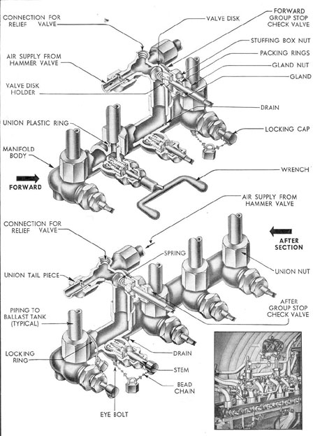
The 600-pound MBT blow manifold is
made up of two parts, the forward section and
the after section. The upper half of Figure
3-2 shows the construction of the forward
section of the manifold. The after section is
of similar construction (lower half of Figure
3-2) except that it contains one additional
blow valve. The forward section has four
blow valves and the after section of the manifold
has five blow valves.
The blow valves and the two group stop
check valves have no permanently attached
handles, but are provided with square-ended
stems. A double-handled socket wrench is
supplied to fit these stems, and the valves are
opened and shut by applying the valve wrench
to one stem at a time. This lessens the possibility
of accidentally opening or shutting the
wrong valve.
The stems of the blow valves for the fuel
ballast tanks are furnished with chain-attached
locking caps and padlocks as a safe
guard against accidental blowing of the tanks
when they contain fuel oil.
Both sections of the 600-pound MBT
blow manifold, as well as the lines carrying
the 600-pound air, are capable of withstanding
depth pressure.
High-pressure air, controlled* by one or
both manually operated hammer valves, passes
through the group stop check valves into the
two sections of the 600-pound MBT blow manifold.
From there it is directed by the blow
valves into the blow lines connecting with
the main ballast tanks. When all the tanks
are to be blown simultaneously, the tank blow
valves on the manifold, the two group stop
check valves, and a hammer valve are opened
in the order given. When the tanks in either
the forward or the after group are to be
blown, the blow valves, the group stop check
valve for that group, and the hammer valve
are opened. When the tanks are to be blown
separately, the individual tank blow valves,
the corresponding group stop check valve or
valves, and the hammer valve are opened in
the order given.
When the ship is rigged for diving, all
individual tank blow valves on the 600-pound
MBT blow manifold, as well as the two group
stop check valves, are open.
Detailed instructions for main ballast
tank blowing operations are given in Chapter 8.
*Hammer valves are not automatic reducers. They
control air pressure only by regulating the volume
of air admitted to the system.