2A1. Introduction. Figure 2-1 shows the
location and relationship of the individual
units that comprise the high-pressure 3000-pound
air system. It must be noted that 3000
pounds is the maximum working pressure of
the system and not a constant pressure; actually,
the pressure may vary between 1500
and 3000 psi. The system is hydrostatically
tested up to 4500 psi or 150 percent of the
working pressure. The system extends from
the high-pressure air compressors in the pump
room to the receiving and distributing manifolds
in the control room, and from there forward
to the torpedo impulse air system in
the forward torpedo room, athwartship to
the air banks, and aft to the torpedo impulse
air system in the after torpedo room.
In Sections 2A2 through 2A4, immediately following,
a more detailed description
of the general layout of the high-pressure air
system is given. In Sections B through F of
this chapter, component parts of the system
are described and the function of each is explained.
Complete instructions for specific operations
of the 3000-pound air system, and schematic
drawings showing the flow of it within
the system are given in Chapter 7.
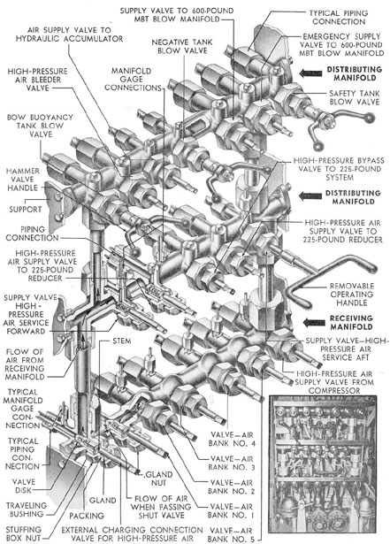
2A2. Manifolds and lines. The high-pressure
manifold (made up of a receiving manifold
and two distributing manifolds) is
mounted on the starboard side of the control
room. The receiving manifold receives air
from two high-pressure air compressors, and
directs it to the air banks, where it is stored.
As the air is needed, it flows back through the
same piping to the receiving manifold, where
it is directed to the distributing manifold.
This operation is controlled by the valves on
the manifold. (See Figure 2-2.)
The 3000-pound service air lines supply
air at a pressure up to 3000 psi to the forward
and after torpedo rooms and to the reducing
valves and engine-starting flasks in each engine
room. The reducing valves furnish
engine-starting air at a pressure of 500 psi,
either directly from the 3000-pound air service
lines, or from the engine-starting flasks
which store the air for use in starting the
diesel engines.
The distributing manifolds distribute air
to the safety and negative tank blow lines, the
main ballast tanks blow manifold, the hydraulic
accumulator air flask, the high-pressure
air bleeder, the bow buoyancy tank blow
line, the 225-pound service air system, and the
forward and after 3000-pound service air lines.
2A3. Air banks. Each of the five air banks
consists of seven flasks, with the exception
of the No. 1 air bank, which has eight. Each
flask is provided with a drain valve. The total
capacity of the air banks is 560 cubic feet.
The No 1 air bank is located inside the
pressure hull, with four flasks in each battery
compartment. The other four air banks are
located in the main ballast tanks. (See Figure
2-1.)
2A4. Torpedo impulse air system. The torpedo
impulse air system stores and controls
the air used to discharge the torpedoes from
the tubes in firing.
The 3000-pound air service line forward,
extending from the distributing manifold,
ends with a 3000-pound to 600-pound reducing
valve, from which a line leads to the forward
torpedo impulse air system. This system is
composed of two impulse flask charging manifolds
(Figure 2-1) and six impulse flasks, connected
by lines to the manifolds. The impulse
flasks are mounted above the pressure hull in
the superstructure forward. One impulse
flask charging manifold is located on the port
side of the torpedo room and the other on the
starboard side. Each manifold is used to
charge three flasks with 600-pound air.
3
Figure 2-2. High-pressure air manifold.
4
The 3000-pound air service line aft, extending
from the distributing manifold, ends
with a 3000-pound to 600-pound reducing
valve, through which air is furnished to the
after torpedo impulse air system. This system
consists of one impulse flask charging
manifold with lines leading to the four impulse
flasks provided for the four after torpedo tubes.
The impulse flasks are mounted
below the after torpedo room deck; the
manifold is located on the starboard side. (See
Figure 2-3.)
In both the forward and the after
sections of the torpedo impulse system, a bypass
valve and line are provided, leading from the
3000-pound air service line to the charging
manifold. The bypass valve and line allow
the charging of the impulse flasks in the
event of failure of the reducing valves.
B. HIGH-PRESSURE AIR MANIFOLD
2B1. Description. As explained in Section
2A2, the high-pressure manifold is used to
direct the storage and distribution of air
within the 3000-pound air system.
The high-pressure air manifold is mounted
on the starboard side of the control room, with
the valves facing inboard.
Pressure gages which indicate the pressure
in each air bank and in the receiving
manifold are mounted directly above the
manifold.
Figure 2-2 shows the mechanical construction
of the manifold. It is composed of
one receiving manifold and two distributing
manifolds, interconnected to allow air to
flow through all three. The manifolds are in
horizontal layers, one above another, with
the receiving manifold at the bottom.
The receiving manifold has seven valves
which control connections to the five air
banks, the external charging connection, and
the supply line from the high-pressure air
compressors.
The lower distributing manifold has five
valves which control connections to the two
reducing valves of the 225-pound air system,
the bypass line to the 225-pound air system,
and the forward and after 3000-pound service
lines. On some of the older fleet type submarines,
there is an additional valve at each
end of the lower distributing manifold which
controls the supply of air from the receiving
manifold to the distributing manifolds.
The upper distributing manifold has
seven ports which connect in sequence to the
bow buoyancy tank blow valve, the high-pressure
air bleeder valve, the air valve to the
hydraulic accumulator, the negative tank blow
valve, the supply valve to the 600-pound MBT
blow manifold, the emergency supply valve
to the 600-pound MBT blow manifold, and the
safety tank blow valve.
The inset in Figure 2-2 shows the hammer
valves (older type boats) which are the
high-pressure blow for bow buoyancy, negative,
and safety tanks in the lines between the
high-pressure manifold and the above mentioned
tanks. Note that this arrangement differs
from the high-pressure manifold illustrated
in Figure 2-2 where the hammer valves for
blowing bow buoyancy, negative, and safety
tanks are on the manifold itself.
Air at pressures up to 3000 psi is delivered
by the compressors through the receiving
manifold to the air banks where it
is stored. As the air is needed, it flows back
from the air banks to the receiving manifold.
To place an air bank on service, the valve that
controls that bank at the receiving manifold
is opened. An air bank should be placed on
service only if its pressure gage registers
above 1500 psi.
When the submarine is rigged for surface,
one air bank is on service. When it is
rigged for diving, three banks are placed on
service.
5
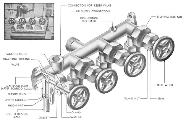
Figure 2-3. After torpedo impulse charging manifold.
2C1. Description. The air used in the
3000-pound air system is compressed by two
high-pressure air compressors mounted in the pump
room, one on each side of the centerline.
The air compressors are of the four-stage
vertical type with a direct electric motor
drive. Starting and stopping of the compressors
are controlled by manually operated
electric switches located in the pump room
near the compressors. The mechanical details
of the compressor and its accessory equipment
are shown in Figure 2-4.
The major components of the high-pressure
compressor are the cylinder blocks with
compression stages or cylinders, the center
frame which houses the crankshaft, and the
base which supports the entire assembly and
contains the first and second stage intercoolers.
The left-hand cylinder block consists of
the third stage cylinder head and shell serving
as a head for the left-hand first and second
stage (differential) cylinder. The right-hand
cylinder block is similar, except that the
fourth stage cylinder head and shell form the
head of the right-hand first and second-stage
(differential) cylinder. Each differential cylinder
(left- and right-hand) contains a differential
piston operating both the first and
second stages. There is one piston for the
third stage and one for the fourth. The third
and fourth stage pistons are of the built-up
type and are attached to the top of the first
and second stage (differential) pistons.
2C2. Compression stages. When the compressor
is operating, air at atmospheric pressure
enters through the top inlet port, passes
through the strainer, muffler, and first stage
suction valves, and enters the two first stage
cylinders on the downward stroke. The upward
stroke of the first stage piston compresses
this air to 31-38 psi and forces it past
the first stage discharge valves. This air
passes through the first stage intercooler,
giving up its heat of compression, and then
through the second stage suction valves and
the two second stage cylinders on the upward
stroke.
On the downward stroke of the two
second stage pistons the air is compressed to
a pressure of 170-185 psi and is forced past the
second stage discharge valves. This air passes
through the second stage intercooler, giving
up its heat of compression for that stage.
The air then enters the third stage through
its suction valves, on the downward stroke
of the third stage piston. On the upward
stroke of the third stage piston, this air is
compressed to 800-860 psi and is forced past
the third stage discharge valves. This air
passes through the third stage intercooler,
giving up its heat of compression for that
stage.
The air then enters the fourth stage cylinder
through its suction valves on the downward
stroke of the fourth stage piston. On
the upward stroke of the fourth stage piston,
the air is further compressed and discharged
through the fourth stage discharge valves
and against the pressure that happens to be
in the bank being charged, thus building up
the pressure in the bank to 3000 psi. This air
passes through the aftercooler, the check
valve, the separator, the charging stop valve,
and up to the high-pressure receiving manifold.
Each compression stage is furnished with
a safety valve, two thermometers, a pressure
gage, a water separator, and a drain valve.
The safety valves are set to blow when the
internal pressure in the stage exceeds the
allowable safe working pressure. The thermometers
indicate the air temperature at the
inlet and outlet port of each stage. The pressure
gages, grouped together on the gage
board, indicate the pressure condition within
each compression cylinder. The drain valves
are used to drain moisture from each stage
cooler separator.
2C3. Lubrication. Lubrication is accomplished
by two systems, the pressure system
and the forced-feed lubricator. The forced-feed
lubricator, controlled by four adjusting
knobs, supplies oil to the piston rings, cylinders,
and air valves. The pressure system is
supplied with oil by a rotary oil pump
actuated by the crankshaft. Oil circulates
7
from the oil sump, through a Cuno oil filter
to all bearing surfaces in the compressor.
Oil for the pressure system is cooled by the
oil cooler attached to the after end of the bed
plate.
2C4. Cooling. As in the automobile engine,
the pistons and cylinders of the compressor
must be cooled to prevent damage by the heat
developed by the compression of air. A
water-circulating system is used for this purpose.
Cooling water is supplied to the pipe header
by means of a water pump attached to the left
side of the center frame. From there, water
is distributed through branch piping to the
intercoolers, the aftercooler, the oil cooler,
and the cylinder water jackets. Finally, it is
discharged overboard.
The relief valves at the second and third
intercoolers and at the aftercooler are set to
open when the, water pressure in the system
exceeds 150 psi. The cooling system requires
approximately 35 gallons of water per minute
at 70 degrees Fahrenheit.
2C5. Operating principles. Each
compressor has a capacity of 20 cubic feet per hour at
3000 psi.
To start the compressor, the valves in the
water cooling line, the discharge drain valve
in the fourth stage, and all drain valves from
the air piping of the compressor are opened.
Then the motor is started by pressing the
push-button controls, and the speed is regulated
by adjusting the rheostat. After the
normal speed has been reached, the first,
second, third, and fourth stage drain valves
are closed successively, allowing the pressure
within the stages to be built up gradually.
The oil pressure must also be up to the proper
point before the machine is placed in service.
In securing the compressor, the current
is turned off and all stage drain valves are
opened. The pressure within the compressor
is gradually reduced. The check valve
at the aftercooler prevents the compressed air
in the ship's banks from backing up.
The speed of the compressor should never
exceed 550 rpm, because overspeeding may
damage the moving parts and the valves.
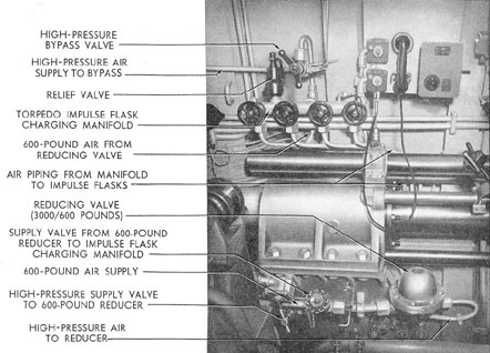
Figure 2-5. Reducing valve and bypass to torpedo impulse charging manifold.
8
D. TORPEDO IMPULSE FLASKS
2D1. Description. The impulse flasks, forming
part of the impulse air system mentioned
in Section 2A4, are steel cylinders, dome-shaped
at each end. One of the domed ends is
flanged and is provided with a port which
connects to the impulse lines. There is an
impulse flask for each torpedo tube. The six
flasks that are mounted in the superstructure
above the forward torpedo room are approximately
5 feet 10 inches in length and 16 inches
in diameter; the four flasks mounted below
the after torpedo room deck are approximately
5 feet 3 inches, in length and 18 inches
in diameter.
A torpedo impulse flask has a capacity of
approximately 7 cubic feet. It stores air which
is received through the charging line from
the torpedo impulse charging manifold at a
pressure of 600 psi. The air that is stored in
the impulse flasks is used in firing the torpedoes
from the torpedo tubes. A swing
check valve prevents the air from being forced
back to the manifold. Each impulse flask is
connected to the corresponding torpedo firing
valve by a line bypassing the swing check
valve.
When the torpedo firing valve is opened,
air from the impulse flask discharges into the
breech of the torpedo tube, forcing the torpedo
out of the tube.
The impulse flask, charging manifold,
valves, and lines are tested hydrostatically to
a pressure of 900 psi or 150 percent of the
maximum working pressure.
E. BYPASS AND REDUCING VALVES FOR 600-POUND
TORPEDO TUBE IMPULSE AIR SYSTEM
2E1. Description. The reducing valves provide
the torpedo tube impulse system with
600-pound air by reducing the 3000-pound
pressure of the high-pressure air system to
600 pounds. In practice, the reducing valves
may be set below 600 pounds for a lower impulse
pressure.* Bypass lines with manually
operated bypass valves are provided to supply
high-pressure air directly from the 3000-pound
service lines to the torpedo impulse
system in the event of failure of a reducing
valve, or in the event that an impulse pressure
above the reducer setting is required.
One reducing valve is installed at the
end of the forward 3000-pound air service line
on the starboard side of the forward torpedo
room, and another at the end of the after
3000-pound air service line in the after torpedo
room. The bypass valve and line are
located above the reducing valve in each case.
(See Figure 2-5.) In the forward torpedo
room, the reducing valve and the bypass valve
and line supply two torpedo impulse flask
charging manifolds. In the after torpedo
room, they supply one manifold.
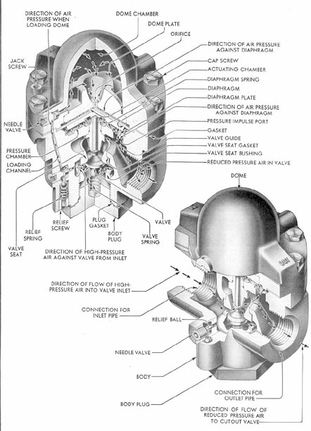
The reducing valves are of the balanced
*Pressures as low as 300 pounds at periscope depth
are used.
pressure type, set to receive air at a pressure
of 3000 psi and to discharge it at a
pressure of 600 pounds.
The mechanical construction of the valve
is shown in Figure 2-6. A detailed description
is given in Section 4C.
2E2. Operation. To supply air to the torpedo
impulse air system, the stop valves on
both sides of the reducing valve are opened.
This allows air to enter the high-pressure side
of the reducing valve. When the pressure in
the torpedo impulse flask charging lines is
less than 600 psi, the diaphragm in the reducing
valve unseats the valve disk, permitting
the high-pressure air to enter the lines. The
entering air is instantly reduced to the
required pressure by the valve action. It
continues to flow until a pressure of 600 psi has
been built up in the torpedo impulse flask
charging lines. With the slightest drop in
the pressure on the discharge side of the
reducing valve, the pressure in the dome forces
the valve open, allowing a controlled volume
of air to pass, and thereby maintaining the
delivery at a constant pressure of 600 pounds.
The bypass valve allows air to enter the
torpedo impulse flask charging manifold
9
Figure 2-6. Grove reducing valve.
10
directly from the 3000-pound service line without
passing through the reducing valve. The
bypass valve should be opened slowly, allowing
the high-pressure air to enter the lines
gradually. It should be shut as soon as the
pressure gage registers 600 psi in the torpedo
impulse air system.
F. TORPEDO IMPULSE CHARGING MANIFOLDS
2F1. Description. The torpedo impulse flask
charging manifolds charge the torpedo
impulse flasks described in Section 2D. There
are three such manifolds aboard the vessel,
two in the forward torpedo room each serving
three flasks, and one in the after torpedo
room serving four flasks.
Figure 2-3 is an illustration of the charging
manifold in the after torpedo room. Its
construction is typical of all three manifolds.
It consists of a cast-bronze body, cylindrical
in shape, with four valves and pipe connections
leading to the four impulse flasks, a
supply line connection, a pressure gage connection,
and a relief valve connection. The
relief valve, of the type described in Section
4I, is set to blow when the pressure in the
manifold exceeds 675 psi. Each valve is
operated by a handwheel, on the rim of which
is stamped the function of the valve.
The two impulse flask charging manifolds
in the forward torpedo room are of similar
construction, except that each serves only
three impulse flasks and therefore is provided
with only three valves and pipe connections.
Air is supplied to the charging manifolds
at 600 psi from the 3000-to-600-pound reducing
valve described in Section 2E. To charge
a flask, the reducing valve must be opened to
permit air to enter the chamber of the manifold.
When the manifold pressure registers
600 pounds, the valve directing the flow from
the charging manifold to the selected impulse
flask is opened. The flask is fully charged
when its pressure gage reads 600 psi.