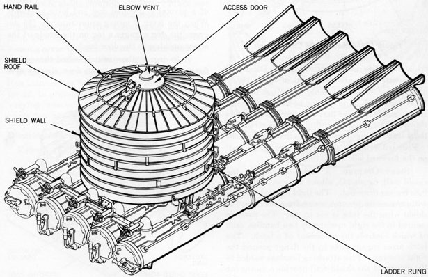
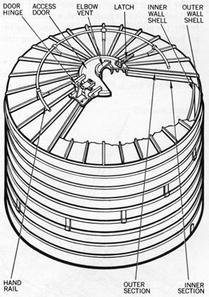
The 21" AW Torpedo Tube Blast Shield Mk 1 Mod 2 is a cylindrical enclosure which is mounted only on 21" AW Torpedo Tube Mk 15. General arrangement of the blast shield is illustrated in figure 138.
The blast shield protects the tube trainer and the gyro setter from the blast or concussion from the ship's guns.
Design Features
Ventilation for the blast shield is provided by
an elbow arrangement in the top of the access door.
The blast shield is bolted to pads and brackets
on the barrels and is situated on the torpedo tube
so that it completely encloses the controls and instruments operated by the gyro setter and tube trainer. An access door, handrail, and ladder rungs provide for getting in and out of the blast shield.
Components
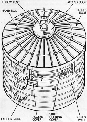
Each blast shield assembly, figure 139, consists of two principal components, the shield wall and the shield roof.
Component Description
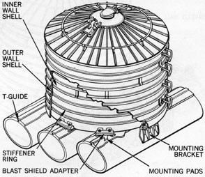
Shield Wall. The blast shield wall consists of an outer and inner shell, both of which are made of corrosion resisting steel plate, 0.05 inch thick. These walls are welded to horizontal stiffener rings
Figure 138-Blast Shield Mk 1 Mod 2, Right View.
130
Figure 139-Blast Shield Components.
to add rigidity to the construction. Details of wall construction are illustrated in figure 140.
The blast shield assembly is bolted to pads formed on the T-guides on top of the right-center, center, and left-center barrels. The shield also is secured to two steel mounting brackets riveted to the sides of the right-center and left-center barrels.
Four ladder rungs are bolted to the shield wall on the forward side of the blast shield.
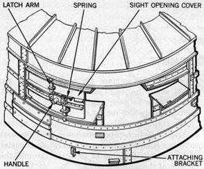
SIGHT OPENING. A sight opening in the shield wall, figure 141, allows the gyro setter and tube trainer to see out. The sight opening is fitted with a cover to prevent water from entering the shield when the tube is not in use. The cover is secured in the sight opening by two handles, each of which controls the movement of a latch. The latch arms engage slots in the flange around the sight opening. Five attaching brackets welded to the outside of the shield wall provide a means for stowing this cover when it is removed from the sight opening.
Shield Roof. The conical-shaped roof, figure 142, is made up of inner and outer sections of corrosion resisting steel plate which are welded to vertical stiffeners. The entire roof assembly is welded to the blast shield wall.
A circular handrail on the roof is supported by eight brackets, each of which is riveted to a vertical rib.
An access opening, 20 inches in diameter, formed in the center of the roof, is fitted with a hinged door and latch.
ACCESS DOOR. The circular access door is made from sheet steel plate and consists of an inner and outer shell.
The door hinge, located either forward or aft, is bolted to the roof on one end and welded to the access door on the other. A lug formed on the roof end of the hinge acts as a stop when the door is opened. The door can be secured open by a pin which is fastened to the hinge with a chain.
A latch, directly opposite the hinge, consists of a pivotally mounted dog and lever assembly. When the lever is swung approximately 135 degrees, the dog engages a lug on the inside of the access opening to the door latch.
A 90-degree elbow vent is bolted through its flange to the top of the access door directly over its ventilator opening.
Figure 140-Blast Shield Wall, Sectional View.
131
Figure 141-Sight Opening and Cover,
Sectional View.
Maintenance
Inspection. Make a WEEKLY inspection to see that all moving parts, such as the access door hinge and latch and the latches on the sight opening cover, are in good operating condition. Make sure ladder rungs and handrail are secure.
Lubrication. Oil the access cover hinge and latch assembly as well as the latches on the sight opening cover WEEKLY. Refer to charts and lubrication instructions in chapter 12.
Preservation. Carefully follow the lubrication instructions for all parts, as covered in chapter 12, to prevent corrosive effects of the sea and varying weather conditions. Keep all moving parts free of corrosion and foreign matter.
Disassembly and Reassembly
Removal From Tube.
1. Before removing the blast shield from the tube, remove the tripping latch connecting rod, which projects through the side wall of the shield.
2. Unscrew the 12 studs attached to the T-guides on the right-center, center, and left-center
barrels. Also, unscrew the four studs attached to the two steel brackets on the sides of the right-center and left-center barrels.
3. With a sling attachment and crane, lift the blast shield from the tube.
Disassembly and Reassembly. Disassembly of the access door, handrail, sight opening cover, and ladder rungs is apparent after a study of BuOrd general arrangement dwg 217763. Reassembly is in the reverse order of disassembly.
Installation. Installation of the blast shield is in reverse order of removal; use BuOrd dwg 217763 as a guide.
Figure 142-Blast Shield Roof, Sectional View.
132
Chapter 10 HEATING EQUIPMENT
General
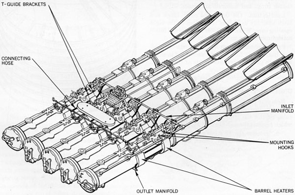
The heating equipment keeps the torpedo after-bodies and the mount training circle warm enough for normal operation with outside air temperature as low as 10 degrees Fahrenheit. This steam type equipment, figure 143, connects to the ship's auxiliary exhaust steam supply.
The heating equipment consists of four curved shell heater units for each barrel, a training circle heater, the piping and fittings for connecting barrel heaters to each other and to the training circle heater, and inlet and outlet connections.
Four heaters are mounted on each barrel, two on each side, located as shown in figure 143. Each heater, figure 144, is fitted closely to its barrel and
covers the side surface for approximately ten inches along the longitudinal axis of the barrel. The distance between adjacent barrel heaters is approximately 25.5 inches.
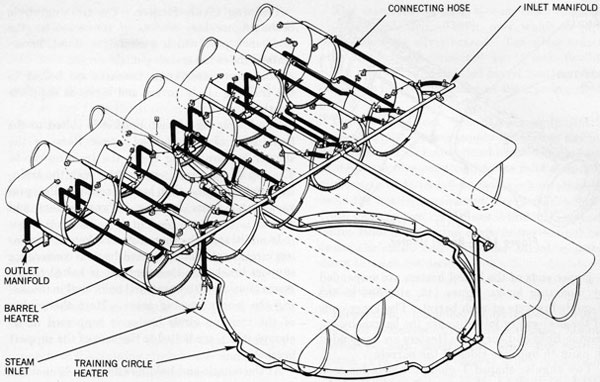
The training circle heater consists of several lengths of 1/2-inch pipe with suitable connections to form a circular shape having an inside diameter of 79 inches. This heater is located around the outside of the training circle.
A revised model makes the heater an integral part of the training circle cover. When the training circle cover must be replaced, the revision shown in BuOrd dwgs 517613 and 517614 should be used.
The inlet manifold, a brass pipe 118 inches long, extends across and above the five barrels, in front
Figure 143-Heating Equipment.
133
Figure 144-Piping, Component Arrangement.
of the barrel heaters. This manifold connects to the individual heaters to deliver live steam from the inlet connection.
An outlet manifold of brass pipe 116.5 inches long, extends across and below the five barrels in back of the barrel heaters. The manifold connects to the individual heaters to collect condensation and return it to the ship's fresh water system.
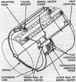
Barrel heater covers consist of three layers of asbestos paper next to the heater shell, to serve as insulation, and a sheet of steel tack-welded to the heater, figure 146.
Design Features
When the steam supply is turned on, the barrel-heating equipment delivers a continuous supply of heat for the torpedo mechanisms. The training circle heater supplies continuous heat for the training circle area to prevent ice from forming between moving parts and to keep lubricating grease soft.
All the piping and fittings are corrosion resistant and are insulated wherever practicable.
Barrel heaters are tested to a pneumatic pressure of 50 pounds per square inch.
Components
The heating equipment, figure 144, consists of the following principal components:
Barrel heaters
Barrel heater covers
Training circle heater
Inlet manifold
Outlet manifold
Connecting hose.
Component Description
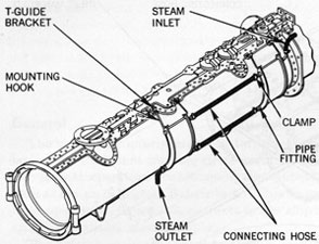
Barrel Heaters. The barrel heaters, figure 145, are curved rectangular shells made of welded steel plate, 1/8-inch thick, rolled to fit the outer contour of the barrel. The curved end plates of the shell project beyond its body; an 11/32-inch hole is drilled in each projection for mounting. Two holes of 3/4-inch diameter are provided in the body portion of each end plate.
Four 1/2-inch half-couplings on each barrel heater serve as the inlet and outlet connections. These couplings are welded over the 3/4-inch holes in the fore and aft ends of the heater shell.
134
Figure 145-Barrel Heater.
Upper ends of the barrel heaters are suspended by mounting hooks, figure 146, attached to the T-guide brackets of each barrel. The lower ends of the heaters are joined under the barrels by extension links and springs. Heaters are suspended in pairs on opposite sides of the barrels.
Two angular-shaped T-guide brackets for each heater are bolted to the barrel T-guides. In the other leg of each bracket, a 3/8-inch hole is drilled for holding the threaded end of the mounting hook.
The mounting hooks are made of zinc-coated cold rolled steel approximately six inches long and %6-inch in diameter. The straight ends of the hooks are threaded for bolting to the free ends of the T-guide brackets; the hook ends are inserted in the 11/32-inch holes at the upper ends of the barrel heaters.
The lower ends of the heaters are connected to each other by means of extension links and springs. The springs and links are hooked to each other and to the 11/32-inch holes in the lower ends of the barrel heaters.
BARREL HEATER COVERS. The barrel heater covers, figure 146, are made of sheet steel, formed to fit tightly over the barrel heaters, insulation, and liner. The covers have 0.30-inch overlapping edges which are tack-welded to the sides of the heaters.
The insulation for the barrel heater covers consists of two outer layers of asbestos paper, 1/16-inch thick. Between the two layers is a liner of corrugated asbestos paper having a thickness of 1/4-inch to 9/32 -inch.
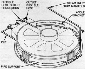
Training Circle Heater. The training circle heater, figure 147, consists of connected lengths of 1/2-inch pipe which encircle the stand, immediately under the training circle covers.
Four sheet-steel angle brackets are bolted to the training circle covers and serve as supports for the pipe.
The longer leg of each bracket is bolted to the training circle covers; the heater rests on the shorter leg projecting under the training circle. The top of the pipe 'is in contact with the training circle cover so that heat is conducted to prevent water from freezing between covers and stand.
In addition to the four angle brackets, the training circle heater is supported by two converging support brackets. Each bracket is bolted to the worm housing with hexagonal bolts used in mounting the worm housing cover. Here the piping of the training circle heater is supported in U-clamps which are bolted to the base of the support brackets.
At the muzzle end hold down clip, a 3/4-inch tee serves as the inlet connection. This tee is connected by 3/4-inch pipe to the inlet manifold between the center and left-center barrels. The
Figure 146-Barrel Heater Cover Attachment.
135
training circle heater has two 3/4-inch outlet tee-connections at the rear of the heater. One tee is connected by a 3/4-inch pipe to the outlet manifold between the left-center and center barrels. The other tee is connected to the steam outlet by a length of flexible hose.
If at any time the training circle covers need replacement, use the covers with the integral heater, as illustrated in BuOrd dwgs 517613 and 517614.
Inlet Manifold Arrangement. The inlet manifold is a brass pipe 118.0 inches long, threaded at both ends. This manifold extends across the top of the five barrels in front of the barrel heaters and is mounted in four support brackets which are bolted to the barrel supporting rings. The manifold has ten 5/8-inch holes and two 13/16-inch holes to which 12 distributing pipe connections are silver-brazed. Ten lengths of 1/2-inch flexible steam hose lead from the silver-brazed connections to the individual barrel heaters. One pipe connects to the training circle heater and the other is the inlet from the ship's steam supply.
Outlet Manifold Arrangement. The outlet manifold is a brass pipe 116.5 inches long, threaded at both ends. This manifold extends across the five barrels, below and to the rear of the barrel heaters. Five supporting bars are bolted to the gyro spindle housing rear cover plates to serve as mounting supports for the manifold.
Figure 147-Training Circle Heater and Flexible
Hose Connection.
The manifold has ten 5/8-inch holes and one 13/16-inch hole drilled in it, over which 11 pipe connections are silver-brazed. Ten silver-brazed pipe fittings are connected by 1/2-inch flexible steam hose to the individual barrel heaters. The outlet ties in with the outlet of the training circle heater.
Connection Hose. The heating equipment is connected to the steam supply by 3/4-inch flexible steam hose. This hose is fitted to the threaded end of a 3/4-inch pipe connected to the inlet manifold.
A length of 3/4-inch flexible steam hose also connects the heating equipment return to the ship's fresh water system. This hose is fitted to a 3/4-inch outlet from the training circle heater located between the center and left-center barrel, running down through the deck.
Maintenance
Inspection. Examine the equipment periodically for evidences of rust and corrosion. Joints should be leak proof, and when the heating system is in operation observe it for evidence of escaping steam. Steam under pressure has a tendency to straighten out the curved heater shells. Therefore, check to assure a metal-to-metal contact of heater shells to tube barrels.
Operating Instructions
Effective Operating Pressure. This heating system with a steam pressure of from 5 to 20 pounds per square inch effectively will keep the heated area above freezing even when the atmospheric temperature is as low as 10 degrees Fahrenheit.
The maximum allowable pressure throughout the heating system is 30 pounds per square inch.
When placing the system in operation, be sure to open the outlet valve before opening the inlet valve.
Operating Precautions. Do not exceed maximum pressure limits; there is danger that the barrel heaters will straighten out, leak, or fail. Metal-to-metal contact of heaters to tube is needed for efficient conduction of heat.
While the heaters are being used, no low pressure points should be allowed in the supply or return pipes because condensation which collects in these low pressure areas will freeze when the steam supply is turned off.
136
Disassembly and Reassembly
Removal. Before removing the heating system from the tube, close the inlet valve and exhaust all steam through the outlet valve. To obtain working space for removing the heating equipment, remove the blast shield, trainer's seat, foot rest, and firing panel bracket.
1. Disconnect the flexible steam hose from the ship's piping and from the inlet and outlet connections; disassemble all piping and fittings.
2. Remove the training circle supports and heater, the manifold clamps from the support bars, and the inlet and outlet manifold from the tube.
3. On tubes where training circle covers with integral heaters have been installed, disconnect from the inlet and outlet manifolds of the tube.
4. Before removing the barrel heaters, raise the torpedo course attachment. Loosen the mounting hooks and remove extension springs and links. Lift the heaters from the mounting hooks and remove them from the barrels.
Disassembly. The heating equipment consists of seven assemblies and, to disassemble the system, these assemblies should be removed in the following sequence:
1. Remove the piping assembly, which includes all the fittings for connecting the barrel heaters to the manifolds and training circle heater.
2. Disassemble connections between barrel heaters.
3. Disconnect the training circle heater assembly, and remove all the piping, supports, and fittings (except on training circle covers with integral heaters.)
4. Disassemble the inlet and outlet manifold assemblies.
5. Disconnect the barrel heater group and the pipe support group.
The barrel heater group includes all the heaters for the barrels and the necessary hooks, links, and springs. The pipe support group contains all the necessary brackets, bolts, and washers that support the piping throughout the system.
Reassembly. Reassemble the heating equipment in reverse order of disassembly. Refer to BuOrd dwgs 233999, 512895, and 245535 for assembly arrangement.
Installation. Locate heaters on barrels as shown on BuOrd dwgs 512895, 512894, 512896, and 245535, and attach them around the barrels with hooks, springs, and extension links as shown on BuOrd dwg 245536. An optional method is shown on BuOrd sk 110552.
1. Install inlet manifold on the four supporting brackets and the outlet manifold on the five supporting bars which are attached to the barrel housing. See BuOrd dwg 512895 for general arrangement of manifold mounting.
2. Install the training circle heater and its supports as shown on BuOrd dwg 233999; set the 0.20-inch clearance between pipe and stand as closely as possible. On tubes where the training circle covers with integral heaters have been installed, it is necessary to connect only the hose and pipes.
3. Assemble all the hose, pipe, and fittings listed on BuOrd dwg 512896 and clamp the inlet pipe to the saddle. Connect the flexible steam hose from the ship's piping to the inlet and outlet connections; insulate the piping wherever practicable.
137
Chapter 11 ELECTRICAL INSTALLATION
General
Power training of the tubes, director orders, firing, and instrument lighting are partly or wholly electrical. This chapter describes the electrical installation of the torpedo tube and connections to other electrical systems of the vessel, explains the operation of the electrical equipment, and gives instructions for inspection, testing, and repair of the electrical system. Fire control equipment and circuits are not part of the torpedo tube installation; they are described in OP 1586, Torpedo Fire Control Equipment Destroyer Type.
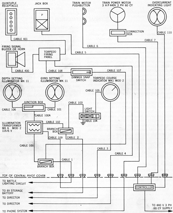
All components of the electrical installation are of waterproof or watertight type. The designation and description of each component is given in figure 148.
All pieces of electrical equipment are surface-mounted either on the structure of the torpedo tube or on the fixed structure of the vessel. Cables enter equipment boxes through watertight bushings; they are secured to structural members by clamps at suitable locations. Where several cables lie in parallel runs on the torpedo tube they are held securely together by serving.
The electrical installation is divided into three major systems, as follows:
Power Train Circuit. The power train circuit includes the power motor and its controls for the train hydraulic drive system connected as shown in figure 86.*
The motor driving the hydraulic system is supplied from the 440-volt 60-cycle three-phase power system of the vessel. The pushbutton for operating the motor controller is in the main 440-volt
* Controller wiring diagram is derived from BuOrd dwg 231761. For other controller wiring diagrams, refer to BuOrd dwgs 268619, 427355, or 365843.
370563 O-56-10
circuit. The overcurrent indicating light is supplied with 6 volts from the illumination circuit.
Controller data are tabulated in chapter 6. The controller is a magnetic type for across-the-line starting. Overload protection consists of thermal trips. A manually operated three-blade line switch is built into the controller; the operating handle extends through the watertight box. In one line of the controller is an overcurrent relay which connects 6 volts to the overcurrent indicating light, whenever line current exceeds the trip setting.
The controller is bulkhead-mounted below the level of the torpedo tube mount near a 440-volt power supply panel.
A total of five cables enter the controller as shown in figure 86. Three of these cables carry 440 volts; and the other two carry 6 volts.
When the operating handle is thrown to ON, the line terminals of the controller and the pushbutton are energized. Then, when the START-EMERG RUN button is pushed, the contactor is energized to close the main contacts and put full line voltage on the motor. When the STOP button is pushed, the contactor circuit is opened to permit the main contacts to open quickly under spring pressure to stop the motor.
If line current exceeds the trip setting, the over-current relay closes the 6-volt circuit to the over-current indicating light on the training crank column to show the trainer that the motor is overloaded. After a variable time, dependent upon the amount of overload, the overload trip reset relay will open the contactor circuit and stop the motor. The tripping time is shorter for larger currents and longer for smaller currents. The motor can be kept operating under overload by holding down the START-EMERG RUN button. However, if line current is greater than 20 amperes, the line fuses will blow and open the circuit.
A current of 10 amperes in the pushbutton circuit will blow the 10-ampere fuse to make the push button inoperative. Normal current in the
138
Figure 148-External Wiring Diagram.
139
pushbutton is one-half ampere; the fuse will blow only if there is a short circuit in the controller wiring.
PUSHBUTTON STATION. The pushbutton is a momentary contact, spring-return type, located on the top left end of the trainer's and gyro setter's seat on the tube mount. There are two buttons, one marked START-EMERG RUN and the other, STOP. One cable leads from the pushbutton station through a terminal tube in the central pivot cover downward to the controller.
ELECTRIC MOTOR. The motor is a completely enclosed squirrel-cage induction motor rated at 3-horsepower, varying duty, 55-degree (C) temperature rise, 440 volts, 1150 revolutions per minute, three phase, 60 cycles. It is designed for starting at full voltage. Complete motor data tare tabulated in chapter 6.
The motor is flange-mounted to the pump housing (reservoir) on the left side of the torpedo tube mount. One cable leads from a watertight terminal box on the motor through a terminal tube in the central pivot cover downward to the controller.
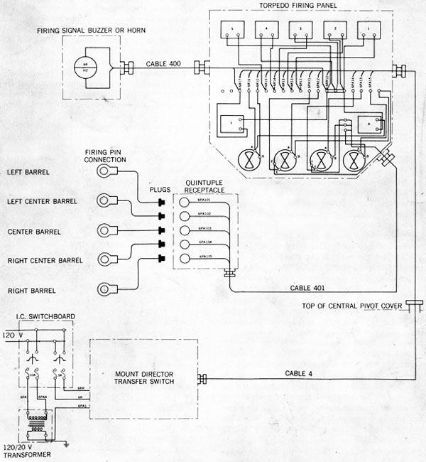
Firing Circuit. The wiring diagram of the firing circuit is shown in figure 149. This circuit consists of two parts, the firing circuit proper (6PA) and the ready light circuit (6R). This circuit transmits firing orders from director to tube mount, ready signals from mount to director, and the firing impulses from the director to the tube firing pins. The firing circuit is supplied from the 120-volt lighting system of the vessel, the 6R circuit directly and the 6PA circuit through a 20-volt transformer.
FUNCTIONAL ARRANGEMENT. The director selector switch directs the Power from the Interior Communications (I. C.) switchboard, figure 74, to either the port or starboard director firing panels. When the switches are closed at the director panel for the desired barrels, corresponding annunciators are energized on the director panel and on the firing panel at the mount. When the indicated barrels are ready the ready switch (OFF-READY) is closed, energizing the ready annunciators on both the director panel and the firing panel. This switch also closes the firing circuit proper except for the two contact makers or triggers at the director station. These contact makers are connected in parallel. When either is closed current flows in series through the contact
maker, through the selected tube ready firing switch or switches, through the ready switch, and finally to the firing pins firing the desired torpedoes. Closing a contact maker also energizes the firing annunciators on both the director panel and firing panel as well as the horn or buzzer.
The tube ready firing switches are connected in parallel so that any desired combination of barrels may be set up and fired.
FIRING PANEL. The torpedo firing panel on the mount is located to the left of the course indicator. It contains seven annunciators, one for each barrel, one for ready signal, and one for the firing signal, and a ready switch (OFF-READY) operated by a large knob.
Four cables are connected to this panel. One cable supplies panel illumination as described under Illumination, page 142. One cable leads to the buzzer or horn firing signal located below the panel. One Able leads to the quintuple receptacle at the breech end of the mount. The fourth cable leads through a terminal tube in the central pivot cover to the torpedo director.
FIRING PIN. The firing pin in back of each cartridge chamber door, figure 20, has one terminal grounded internally. The other terminal is connected by a cable leading to one outlet in the quintuple receptacle. These cables have special terminals which lock into the receptacles.
FIRING TRANSFORMER. The 120- to 20-volt firing transformer is located below deck at the lighting switchboard. The transformer primary is protected by a 10-ampere fuse.
FIRING KEY. There are two firing contactors, both connected with the torpedo director equipment. One key has a pistol grip with a trigger and is attached to the director beside the telescope. The other contactor, in the form of a plunger, is connected to the director by an extension cable so that it may be carried to any point on the bridge of a destroyer.
BUZZER. The audible firing signal is located below the firing panel on the torpedo tube mount. Early installations use a high intensity buzzer. Later installations use a horn. This signal sounds as soon as the firing circuit is completed by operating the firing key.
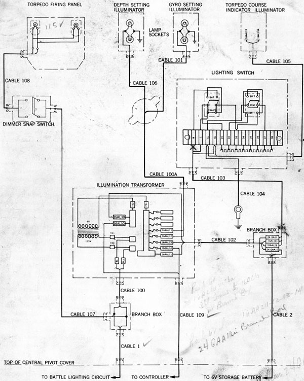
Illumination Circuit. The wiring diagram of the illumination circuit is shown in figure 150. This circuit supplies current for illuminating the controls and instruments on the mount.
140
Figure 149-Firing Circuit Wiring Diagram.
141
Figure 150-Illumination Circuit Wiring Diagram.
142
FUNCTIONAL ARRANGEMENT. The firing panel is lighted from the 115-volt battle lighting system of the vessel. Earlier installations have a snap switch for the panel lights located on a bracket at the right of the panel. Later installations have a dimmer in this circuit located just above the panel.
Lighting for gyro setting, depth setting, and torpedo course indicators is supplied through a switch at 6 volts. Two sources are available, a storage battery and a transformer supplied from the battle lighting circuit. The lighting switch has two handles. One selects either battery or transformer; the other selects either bright or dim lighting. Watertight branch and junction boxes are supplied for cable connections as shown in figure 150. The torpedo control circuits are completed through a cable from the torpedo course indicator to the director. This cable leads downward through a terminal tube in the central pivot cover.
TERMINAL TUBES. All cables leading to the torpedo tube mount pass through terminal tubes which are silver soldered to the central pivot cover, figure 33. At the top of each tube is a stuffing box with a gland and packing to make a watertight seal around the cable. These tubes are curved to pass around the center barrel, four to the right and five to the left.
COMMUNICATION CONNECTION. A watertight jackbox is fitted to the left rear of the trainer's and gyro setter's seat for plugging in a telephone set. The cable from this jackbox leads downward through a terminal tube in the central pivot cover to the telephone system of the vessel.
Maintenance
Practically all failures in electrical equipment of the type discussed in this chapter are caused by: moisture in wiring and fittings, corrosion of contacts, or mechanical damage to wiring. If careful periodic inspections and tests are performed in accordance with these instructions, deterioration usually is discovered before it causes failure in operation.
Inspection. Visually inspect the entire electrical system at least once a week. Examine all exposed cables for cracking, abrasion, and other damage to the covering. Check the slack in the cables where they come down through the terminal tubes in the central pivot; the training motion
twists them at this point. See that all cable clamps and servings are in place and tight. See that the watertight cable bushings at all boxes are tight. Make sure that the covers of all boxes are tight and the gaskets in good condition. See that cover glasses and bull's-eyes on indicators are not broken or loose. See that the operating handles of all switches are held securely in place. During operation, check by touch, the bearing temperature of the hydraulic-drive electric motor. If the hand cannot be held comfortably against the motor for a second the bearing temperature is too high.
Tests. Perform operating tests on the electrical installation periodically to locate incipient failures. These tests are especially important under combat conditions. The frequency of these tests depends upon the type of service and shipboard doctrine. A suggested schedule for the most stringent service conditions is given in the following paragraphs.
DAILY.
1. Test the power training circuit by operating the START-EMERG RUN and STOP pushbuttons to see that the motor starts and stops properly.
2. Test the firing circuit. Open each cartridge chamber door, figure 20, in turn and connect a 20-volt test lamp or a voltmeter between the firing pin and ground. Operate the switches at the director and the torpedo tube mount in the regular firing sequence. Check the operation of annunciators and firing signal and of the 20-volt firing current at the firing pin of each tube.
3. Test the illumination switches and dimmer on all positions to see that the lights operate properly.
WEEKLY.
1. Check the water level and specific gravity of the vessel's 6-volt storage battery.
2. Open the controller box and examine all contacts for dirt and corrosion. See that the asbestos arc chutes on the main contacts are in good condition.
3. Test the overcurrent indicator light by running the motor and closing the overcurrent relay contacts.
WARNING
USE A LONG DRY STICK OR PIECE OF INSULATING ROD; THE VOLTAGE INSIDE THE CONTROLLER IS DANGEROUS TO LIFE.
143
4. Test the overcurrent trip by closing the ON relay contacts; observe the preceding warning.
MONTHLY. Measure the insulation resistance from each line wire of each circuit to ground. Make this test with all switches open. Use a megger or an equally accurate instrument, applying 100 volts to the 6-volt battery circuit and 500 volts to other circuits. Keep a record of insulation resistance measurements; a sudden decrease in the value indicates deterioration which will lead to failure. The insulation resistance of each circuit should be at least 5 megohms. However, the actual value is not as important as a change from the last reading.
Precautions.
1. Do not operate the motor on EMERG RUN when the overcurrent indicator lamp is lighted unless absolutely necessary. Such operation may cause the motor to burn out. Normally, this condition will occur rarely and for a short time only.
2. All voltages in the electrical installation, except the 6-volt storage battery circuit, are dangerous to life. The installation is sealed completely and all external metal parts are grounded so that no injury can result from contact with any external parts. Only qualified electricians should open or perform any work on the inside of the watertight boxes. Servicing should be made in dry weather whenever possible because moist air condenses inside the boxes after they are closed.
3. Always use an insulated fuse puller when replacing fuses.
4. Observe due care when making tests on the firing circuit to prevent accidental firing if the barrels are loaded.
Fuses. The electrical installation is protected by fuses as described below. When replacing fuses always use the specified ampere rating.
POWER TRAINING CIRCUIT. Fuses inside the controller box have the following ampere ratings:
20 amperes in each incoming 440-volt line
10 amperes in one line to the pushbutton.
FIRING CIRCUIT. Fuses at Interior Communications switchboard should be:
10 amperes in each line to primary of the firing transformer
3 amperes in each line to the annunciator circuit (6R).
ILLUMINATION CIRCUIT. Inside the illumination transformer box, the fuses should be 3 amperes in line to each illuminator.
Repair and Replacement
General. Be sure that all electrical connections are tight, that switches work easily, and that all screws are in place and tight on covers of boxes.
Cables. Replace cables which are damaged mechanically or which show abnormally low insulation resistance. If pre-cut and prepared wiring harness replacements are not available, always use the type and size of cable specified and make connections according to the wiring diagram.
Transformers. Burned-out transformer windings usually show the effects of heat. Doubtful transformers should be removed and tested under load by measuring the primary and secondary voltage and current. The firing transformer is rated 120/20 volts, 200 volt-amperes. The lighting transformer is rated 115/6 volts, 50 watts.
Controller. If contracts are dirty, clean them with carbon tetrachloride and crocus cloth. Pitted and burned contacts should be replaced. Replace damaged arc chutes. Replace burned-out relay coils.
Illuminators. Replace cracked and broken glass and burned-out lamps.
Annunciators. Replace damaged or defective annunciators.
Firing Panel Switch. Clean all contacts. Replace entire switch if damaged or defective.
Gaskets. Replace all gaskets on watertight boxes if they are damaged or show signs of deterioration.
144
Chapter 12 LUBRICATION
General
Lubrication instructions for all parts of Torpedo Tubes Mk 14 and Mk 15 are given on three charts. These indicate access locations, designate the required lubricants, and specify the frequency of application.
The lubrication charts are the following BuOrd dwgs:
TITLE
DWG
21" AW Torpedo Tubes (Quintuple) Plan and Elevation
242307
21" AW Torpedo Tubes (Quintuple) Breech End
242308
21" AW Torpedo Tubes (Quintuple) Training Gear
242310
These drawings provide lubrication instructions for all designs and all design variations described herein.
The points of lubrication access indicated on the charts include pressure fittings, grease cups, cover plates, filling plugs, and other devices. Collectively they give access to all points requiring lubrication. They include housed elements of the training gear, sight, stand and saddle, barrel and door mechanisms, firing mechanism, torpedo controls, and tube sight. Reservoir and oil bath
spaces such as the self-contained circulating system of the training gear hydraulic drive are fitted with shaft seals and other special devices for retaining the lubricants, provided specified lubricants are used.
Lubrication facilities include other special devices to aid in removing lubricants, cleaning lubricated areas, or otherwise servicing remote and difficult points of access. Each oil bath space has one or more drain plugs and a covered opening for verifying correct oil level.
A minimum number of lubricating materials are specified by the lubrication charts. All are items of standard service use available at Naval shore stations. They comprise the oils, greases, and compounds identified in table 3.
All materials listed in table 3 are described and their limiting characteristics and purposes are defined in Ordnance Data 3000, Revision B, Lubrication of Ordnance Equipment. This publication is a general reference book for lubrication of ordnance, and may be used in conjunction with the specific exceptions outlined herein and on the lubrication charts.
Table 3 LUBRICANTS
Lubricant
Military Symbol
Specification
Lubricating oil, general purpose
3042* or 3050*
MIL-L-15016
Grease, extreme pressure
MIL-L-17740 (NOrd)
Grease, bearing
MIL-G-16908 (BuOrd)
Grease, ball and roller bearing
MIL-G-18709 (NOrd)
Fluid, power transmission
MIL-F-17111 (NOrd)
Compound, gun slushing
MIL-C-18487 (NOrd) Grade A**
Antiseize compound, high temperature
MIL-C-907 (Ships)***
*Permitted alternates:
For symbol 3042, use symbol 2110 or 2075
For symbol 3050, use symbol 2135
**A non-lubricating compound for use as described in chapter 2.
***A non-lubricating compound for use as described in chapter 7.
145
Lubricating Procedures
Adulterants. A wide variety of soluble corrosive, gumming and generally harmful agents may be added to lubricating oils and compounds, by accident or for the purpose of sabotage. Soluble adulterants in petroleum products can be detected by trained personnel only with appropriate testing equipment. Insoluble abrasives such as emery, carborundum, silica, pumice, etc., may be detected by diluting a drain sample of the oil or grease with several volumes of gasoline and filtering the mixture through chamois. If the presence of harmful agents in any lubricant is suspected, do not use it; operate the equipment with an approved substitute of known purity, or without lubricant.
Lubrication Frequency. The lubrication charts prescribe application of lubricants at regular daily, weekly, and monthly periods, in each instance with intervening periods of operation. In addition, certain parts or mechanisms are designated on the charts or in the instructions of preceding chapters for lubrication quarterly, during a docking period, semiannually, every 18 months, and exercise. These prescribed intervals are vital to good operation and preservation.
Distribution. All lubricants must be distributed by exercising the lubricated parts immediately after lubrication. Exercise assists preservation and, by uniformly distributing lubricant throughout the bearing surfaces, fills voids and assures good performance. Well distributed lubricants prevent galled or scored parts and may prevent parts from becoming seized or frozen.
Excessive Lubrication. Many lubrication points designated on the charts have limited capacity. Sparing application is required even though in some instances the application must be frequent. Excessive lubrication, aside from the external mess of exuding grease and oil, can create serious damage. This is especially true of the electrical installations of torpedo tubes. Excessive use of oil and grease breaks down the insulation of power and communication cables, causes improper switch functioning, and ruins the armatures of motors and generators. Lubrication must be sparingly applied, and also drain points must be open whenever the parts are lubricated.
This is required to remove accumulations of oil, grease, and condensation in the motor cases.
Enclosed gear boxes with provision for oil bath lubrication will overheat and may cause splash penetration into adjacent units if the lubricant is carried above design level. The oil level in each such unit must be checked before operating.
Cleanliness. When handling, applying, and storing lubricants, the importance of cleanliness cannot be overstressed. Because the lubricants come into direct contact with bearing surfaces, the presence of dirt or foreign matter quickly causes damage to vital parts. To prevent such loss the following rules must be observed.
1. Use only clean, fresh lubricants when refilling oil or grease reservoirs and when applying greases or compounds.
2. Always make sure that funnels, grease guns, and other servicing equipment are free from dirt, dust, chemicals, moisture, or other foreign substance.
3. In the instance of disassembled grease-lubricated bearings, the old grease must be removed completely and the bearings and housings must be washed thoroughly before fresh grease is applied.
4. Always store unused lubricants in waterproof and dustproof containers with covers securely seated. Make sure containers are clean and do not use containers which previously have contained corrosive chemicals.
5. When replenishing hydraulic oil, always filter the fluid even if from original containers.
Preservation. Many parts of the torpedo tube are exposed finished metal surfaces that cannot be preserved by painting. They are easy victims for corrosion. They must be observed constantly and treated with prescribed lubricants or other preservatives. This principle of lubrication applies particularly to "after firing" application of preservative coating to barrel interiors, firing mechanism, torpedo stops, gyro and depth setting mechanisms. It is NOT sufficient merely to apply these preservative films; the surfaces first must be cleaned thoroughly and all finger and hand impressions must be neutralized and wiped dry. For additional information as to the importance of good. practice in preserving ordnance, see Ordnance Storage Instructions, OP 1105, chapters 1, 2, and 3.
146
This page is blank.
147
Chapter 13 TOOLS AND ACCESSORIES
General
Tools listed and described in this chapter are used for general maintenance, inspection, adjustment, servicing, repair, replacement, and overhaul of Torpedo Tubes Mk 14 and Mk 15. Accessories described and illustrated are used for preserving, protecting, cleaning, lubricating, testing, and aligning various components of the tube.
All special equipment and standard tools listed herein are identified by Ordnance dwg part number, Federal Standard Stock Catalog number, or the Catalog of Navy Material item number.
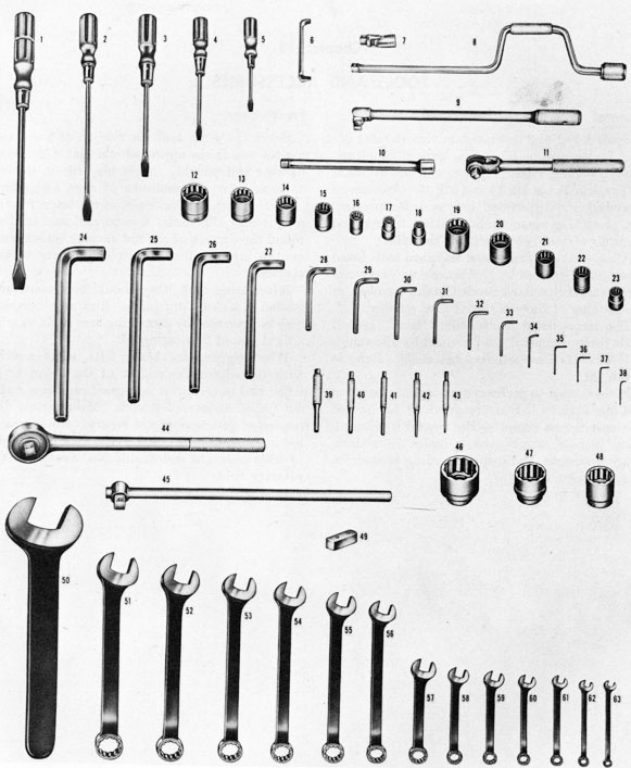
The items listed as "standard tools" are all those tools of general use provided by allowances in NAVORD Standard Tool List 20990. Refer to figure 151.
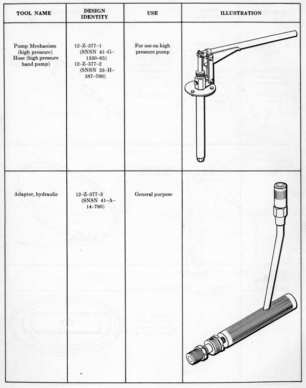
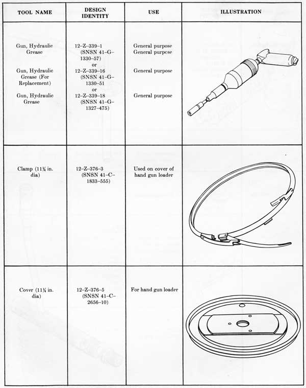
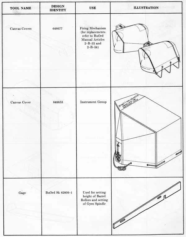
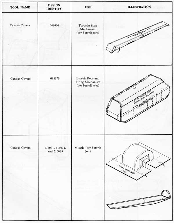
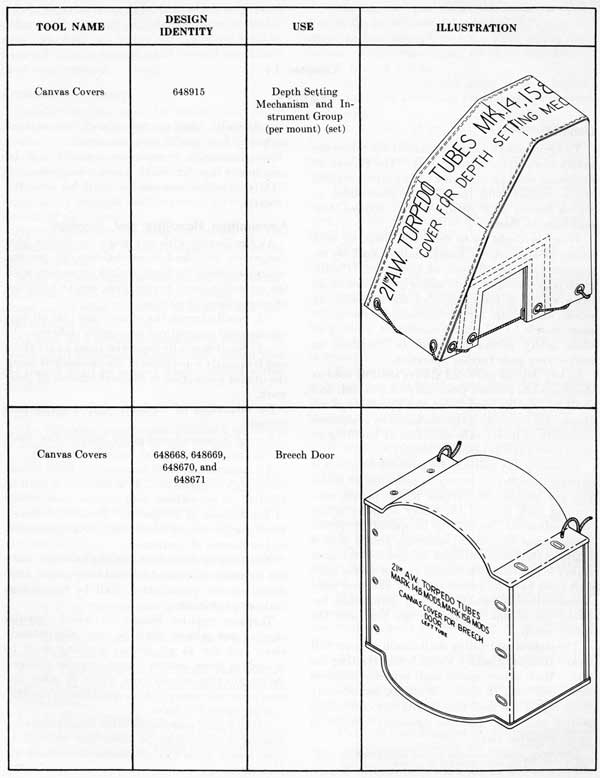
Items shaped to perform a particular operation and standard tools that are provided for limited and specific use comprise the special equipment. They include canvas covers, hydraulic maintenance, boresight, and torpedo loading accessories. Refer to pages 148 to 157.
Precautions
Select the right tool for the job at hand and use the tool in the approved manner. Otherwise, damage and possibly injury may result, as well as unnecessary expenditure of time and effort.
If a wrench, for example, is too large for the nut, it may slip under a hard pull and tend to round the corners of the nut causing undue wear on the jaws of the wrench and injury to the operator.
After using tools, they should be cleaned and stowed in a clean, dry place. Rust and corrosion may be prevented by protecting bare surfaces with a light film of lubricating oil.
When rigging for heavy lifts, select a sling with regard for the weight of the object to be lifted and be certain it is in good condition without frayed or severed strands. Make certain disconnected components are secured properly and not in danger of dropping to the deck below. As in other phases of seamanship, make safety first a primary rule.
148
Figure 151-Standard Tools.
149
KEY LIST FOR FIGURE 151
TOOL NAME
DESIGN IDENTITY
No.
Combination Open-End and Box Wrenches:
3/8 in Nominal opening
12-Z-732-1 or 12-Z-721-1 (SNSN 41-W-1300)
62
1/2 in Nominal opening
12-Z-732-2 or 12-Z-721-25 (SNSN 41-W-1302)
60
9/16 in Nominal opening
12-Z-732-3 or 12-Z-721-26 (SNSN 41-W-1303)
59
5/8 in Nominal opening
12-Z-732-4 or 12-Z-721-26 (SNSN 41-W-1304)
58
3/4 in Nominal opening
12-Z-732-5 or 12-Z-721-27 (SNSN 41-W-1305)
57
13/16 in Nominal opening
12-Z-732-6 or 12-Z-721-27 (SNSN 41-W-1306)
56
7/8 in Nominal opening
12-Z-732-7 or 12-Z-721-28 (SNSN 41-W-1307)
55
1 in Nominal opening
12-Z-732-8 or 12-Z-721-34 (SNSN 41-W-1309)
53
1 1/8 in Nominal opening
12-Z-732-9 or 12-Z-721-34 (SNSN 41-W-1310)
52
1 1/4 in Nominal opening
12-Z-732-10 or 12-Z-721-35 (SNSN 41-W-1310-50)
51
5/16 in Nominal opening
12-Z-732-11 or 12-Z-721-0222
63
7/16 in Nominal opening
12-Z-732-12 or 12-Z-721-25 (SNSN 41-W--1301)
61
15/16 in Nominal opening
12-Z-732-14 or 12-Z-721-28 (SNSN 41-W-1308)
54
Socket Wrench Set:
(1/2 in Drive)
Handle, socket wrench, speeder
12-Z-724-1 (SNSN 41-H-1508)
8
Bar, socket wrench, extension
12-Z-724-4 (SNSN 41-B-309)
10
Handle, socket wrench, spin type
12-Z-724-6
9
Handle, socket wrench, ratchet, reversible
12-Z-724-7 (SNSN 41-H-1505)
11
Joint, socket wrench, universal
12-Z-724-8 (SNSN 41-J-380)
7
Connector, socket wrench, plug
12-Z-724-9
49
Wrench, socket (7/16 in opening)
12-Z-724-10 (SNSN 41-W-3005)
18
Wrench, socket (1/2 in opening)
12-Z-724-11 (SNSN 41-W-3007)
17
Wrench, socket (9/16 in opening)
12-Z-724-12 (SNSN 41-W-3009)
23
Wrench, socket (5/8 in opening)
12-Z-724-14 (SNSN 41-W-3013)
16
Wrench, socket (3/4 in opening)
12-Z-724-17 (SNSN 41-W-3017)
22
Wrench, socket (13/16 in opening)
12-Z-724-19 (SNSN 41-W-3021)
15
Wrench, socket (7/8 in opening)
12-Z-724-20 (SNSN 41-W-3023)
21
Wrench, socket (15/16 in opening)
12-Z-724-21 (SNSN 41-W-3025)
14
Wrench, socket (1 in opening)
12-Z-724-23 (SNSN 41-W-3027)
20
Wrench, socket (1 1/16 in opening)
12-Z-724-24 (SNSN 41-W-3028)
13
Wrench, socket (1 1/8 in opening)
12-Z-724-25 (SNSN 41-W-3029)
19
Wrench, socket (1 1/4 in opening)
12--Z-724-26
12
Socket Wrench Set:
(3/4 in Drive)
Handle, socket wrench, ratchet, reversible
12-Z-731-1 (SNSN 41-H-1506)
44
Handle, socket wrench, T, sliding
12-Z-731-4 or 12-Z-731-5 (SNSN 41-H-1509-60)
45
Wrench, socket (1 5/16 in opening)
12-Z-731-7 (SNSN 41-W-3040)
48
Wrench, socket (1 1/2 in opening)
12-Z-731-8
47
Wrench, socket (1 7/8 in opening)
12-Z-731-9
46
Screwdrivers:
Screwdriver, 4 in
12-Z-705-2 (SNSN 41-S-1102)
5
Screwdriver, 6 in
12-Z-705-3 (SNSN 41-S-1104)
4
Screwdriver, 8 in
12-Z-705-4 (SNSN 41-S-1106)
3
Screwdriver, 12 in
12-Z-705-5 (SNSN 41-S-1110)
2
Screwdriver, 15 in
12-Z-705-6
1
Screwdriver, offset
12-2-705-18
6
Allen Wrenches:
Wrenches (keys) setscrew, hexagon
Across flats
3/32 in
12-Z-723-1 (SNSN 41-W-2449)
35
1/8 in
12-Z-723-2 (SNSN 41-W-2450)
34
3/32 in
12-Z-723-3 (SNSN 41-W-2451)
33
3/16 in
12-Z-723-4 (SNSN 41-W-2452)
32
7/32 in
12-Z-723-5 (SNSN 41-W-2453)
31
1/4 in
12-Z-723-6 (SNSN 41-W-2454)
30
5/16 in
12-Z-723-7
29
3/8 in
12-Z-723-8
28
1/2 in
12-Z-723-9
27
9/16 in
12-Z-723-10
26
.05 in
12-Z-723-11 (SNSN 41-W-2444)
38
1/16 in
12-Z-723-12 (SNSN 41-W-2445)
37
5/64 in
12-Z-723-13 (SNSN 41-W-2446)
36
5/8 in
12-Z-723-14
25
3/4 in
12-Z-723-15
24
Engineer's Wrench:
Single end (2 1/4 in nominal opening)
12-Z-721-15 (SNSN 41-W-1232)
50
Drive pin punches:
Punch, 3/32 in
12-Z-733-1 (SNSN 41-P-3601)
43
Punch, 5/32 in
12-Z-733-2 (SNSN 41-P-3603)
42
Punch, 3/16 in
12-Z-733-3 (SNSN 41-P-3604)
41
Punch, 1/4 in
12-Z-733-4 (SNSN 41-P-3606)
40
Punch, 5/16 in
12-Z-733-5 (SNSN 41-P-3607)
39
150
Tool Name
Design Identity
Use
Adjustable Wrenches:
Wrench, adjustable spanner
12-Z-715-0117 (SNSN 41-W-3249-925)
General purpose
Wrench, adjustable spanner
12-Z-715-0118 (SNSN 41-W- 3250-15)
General purpose
Wrench, adjustable spanner
12-Z-715-0119 (SNSN 41-W-3250-65)
General purpose
Wrench, adjustable spanner
12-Z-715-0120 (SNSN 41-W-3250-50)
General purpose
Wrench, adjustable spanner
12-Z-715-0121 (SNSN 41-W-3249-950)
General purpose
Spanner Wrenches (face type):
Wrench, face spanner
12-Z-714-0127 (SNSN 41-W-3247-710)
General purpose
Wrench, face spanner
12-Z-714-0128 (SNSN 41-W-3247-715)
General purpose
Wrench, face spanner
12-Z-714-0136 (SNSN 41-W-3247-765)
General purpose
Spanner Wrenches:
Wrench, spanner
46137-14 (Tool No. 169)
Wrench, spanner
8-Z-933-5 (SNSN 41-W-3252-385)
General purpose
Wrenches (single end):
1 3/8 in opening
12-Z-716-0178 (SNSN 41-W-1311-15)
General purpose
1/4 in opening
12-Z-717-0221 (SNSN 41-W-2490)
General purpose
3/8 in opening
12-Z-717-0223 (SNSN 41-W-2492)
General purpose
1 5/16 in opening
12-Z-721-11 (SNSN 41-W-1311)
General purpose
1 1/2 in opening
12-Z-721-12 (SNSN 41-W-1312)
General purpose
Blade, Screwdriver:
Blade, screwdriver (.6875" x .10")
8-Z-909-3 (SNSN 41-B-1340-635)
General purpose
Blade, screwdriver (.875" x .10")
8-Z-909-4 (SNSN 41-B-1340-638)
General purpose
Screwdriver:
Screwdriver, stock assembly
8- Z-909- 900 (SNSN 41-11-1435-200)
General purpose
151
152
153
154
370563 O-56-11
155
156
157
158
Chapter 14 SAFETY
General
To avoid casualties, observance of the following safety precautions is mandatory. The Bureau of Ordnance shall be informed of any circumstances which conflict with these safety precautions or which, for any other reason, require changes in or additions to them.
When in doubt as to the exact meaning of a safety precaution, an interpretation shall be requested from the Bureau of Ordnance. Conditions not covered by these safety precautions may arise which, in the opinion of the commanding officer, may render further operation of the equipment unsafe. Under these conditions, nothing in these safety precautions shall be construed as authorizing such further operation.
Safety devices provided always shall be used as designated to prevent possibility of accident, and shall be kept in good order and operative at all times. All instructions promulgated by competent authority to insure safe operation or handling of equipment shall be observed strictly.
Whenever any motion of a power-driven unit is capable of inflicting injury to personnel or material not visible continuously to the person controlling such motion, the officer or petty officer who authorizes the unit to be moved by power shall, except at general quarters, insure that a safety watch is maintained in areas where such injury is possible both outside and inside the unit, and shall have telephone or other effective voice communication established and maintained between the station controlling the unit and the safety watch.
The station controlling shall obtain a report "all clear" from each safety watch before starting the unit. Each safety watch shall keep his assigned area clear and, if unable to do so, immediately shall report his unit fouled, and the controlling station shall stop the unit promptly until it is again reported clear.
Changes, modifications in, or additions to ordnance material or other material used in connection
therewith, shall not be made without explicit authority from the bureaus concerned.
No ammunition or explosive assembly shall be used in any tube for which it is not designated.
Only practice ammunition shall be used for practice.
Ammunition Handling and Stowage
As familiarity with any work, no matter how dangerous, may lead to carelessness, all persons who supervise or perform work in connection with the inspection, care, preparation, use, or handling of ammunition or explosives-
1. Shall exercise the utmost care that all regulations and instructions are rigidly observed.
2. Shall carefully supervise those under them and frequently warn them of the necessity of using the utmost precaution in the performance of their work.
No relaxation of vigilance shall ever be permitted.
Except in case of emergency, ammunition shall not be transferred during fueling operations.
All ammunition shall be protected from abnormally high temperature. If so exposed, it shall be handled in accordance with current instructions of the Bureau of Ordnance. Permissible maximum storage temperatures shall be as prescribed by the Bureau of Ordnance.
To minimize the risk of fire, explosion, or damage to ammunition and its containers from accidental causes, ammunition shall be handled as little as practicable.
Torpedo impulse lockers in which impulse charges are stowed shall be kept scrupulously clean and dry at all times. Nothing shall be stowed in these lockers except impulse charges. Be certain that no oily rags, waste, or other foreign materials susceptible to spontaneous combustion are stowed in them.
Naked lights, matches, or other flame producing apparatus never shall be taken into or near an open locker while this compartment contains explosives.
159
Before performing any work which may cause either an abnormally high temperature or an intense local heat in a locker, all explosives shall be removed to safe storage until normal conditions have been restored.
Ammunition Supply
Impulse charges shall be loaded into firing chambers for firing purposes only. Test or inspection of ammunition by fitting it into firing chambers is prohibited, except when authorized by specific instructions of the Bureau of Ordnance.
During firing, no other ammunition than that immediately required shall be permitted to remain outside of the locker.
During exercises, charges in excess of the amount required for one run shall not be removed from the locker.
When impulse charges are outside the locker, the locker shall, wherever practicable, be kept closed except when the actual passage of ammunition requires it to be open.
As soon as a cartridge chamber is loaded, the breech shall be closed without delay, except that the breech shall be opened when training across the ship.
Operating Precautions
The following paragraphs contain a summary of precautions described in the various chapters of this pamphlet.
Do not remove propeller locks until ready to
fire.
Make sure all access covers which might permit powder gas to escape from the tube on firing are secure.
In cases of misfire (when an impulse cartridge upon firing has failed to explode) observe the following:
1. Keep the tube mount trained in a safe direction.
2. Keep the breech doors on the firing chamber and the barrel fully closed.
3. Continue attempts to fire both electrically and by percussion at the discretion of the tube captain.
4. If the torpedo is not fired under the above conditions, open the firing key and engage the firing hammer in its PERCUSSION SAFE position.
5. Do not open either the firing chamber door or the barrel door for a period of 30 minutes after the last attempt to fire. This, at the discretion of the commanding officer, is not obligatory in time of action.
6. The crew should never leave a loaded barrel until the preceding precautions have been performed.
7. Dispose of impulse cartridges removed from a loaded cartridge chamber in accordance with current instructions of the Bureau of Ordnance.
Keep tripping latches in the UP position when in port, when work is being done on or near the tube, or when the security of the tube is jeopardized by heavy weather.
Keep breech doors closed when back stop handle is UP.
For greater safety, leave the cartridge chamber door open until after the firing hammer has been placed in its PERCUSSION READY position.
Make sure circuit is open when firing switch is open.
Except under actual combat conditions, when training from side to side, open cartridge chamber doors while training through sectors in which a torpedo, if fired, would strike its own ship.
Make sure impulse case does not slide out when cartridge chamber door is open.
Do not install canvas covers on loaded cartridge chambers.
The firing hammer must not be "let down" on a loaded primer to avoid carrying a heavy load on the firing spring for extended periods. The tube may be fired accidentally in this way.
Observe due care, when making tests on the firing circuit, if firing chambers and barrels are loaded, to prevent accidental firing.
When testing overload indicator light and overcurrent trip, use a dry stick or insulating rod; the voltage inside the controller is dangerous to life.
Always use an insulated fuse puller when replacing fuses.
Only qualified electricians should open or perform any work on the inside of watertight electrical boxes.
Use only tools designed for the intended function and then use them in the approved manner. For example, using a wrench too large for a nut
160
may allow the wrench to slip under a hard pull, resulting in injury to the operator. Pushing on a wrench always is dangerous, for the same reason.
When rigging for heavy lifts, select a sling with regard to the weight of the object to be lifted. Be sure the sling is in good condition without frayed or broken strands.
During disassembly or installation operations, be sure disconnected components are secured properly and not in danger of falling on the operator or to the deck below.
Safety Orders
The following safety orders should be posted on or near the mount:
Know the safety orders and know how each one applies to you.
All men at this station will be instructed by the Torpedo Officer in these orders and the use of the safety equipment.
Conditions requiring special action and not covered by safety orders sometimes develop. Common examples are: electric cable adrift, portable watertight battle lanterns adrift or broken, air or oil leakage. Be alert for unusual conditions and report them immediately to the Torpedo Officer.
In no way change any equipment belonging to this station.
Always use these devices to prevent possibility of accident and do not in any way disable or change them. Report any defect to the Torpedo Officer at once.
Never charge torpedo air flasks above measure stamped on the flask.
Never cool torpedo air flasks artificially by spraying with water.
Torpedo air flasks, accumulators, piping, or other receptacles for compressed air must not be cut.
Torpedo air flasks shall not be transferred, hoisted, or chipped in a charged condition.
When receiving a torpedo, the propeller lock shall be put on immediately. The propeller lock shall be kept on at all times when the torpedo is in the tube except when testing or firing.
When hoisting a torpedo on board nose and tail lines shall be used. Care shall be taken at all times when transferring or handling torpedoes not to damage the torpedo in any manner.
When charging torpedo air flasks, a torpedo-man shall be stationed at the air gage and air line stop valve during the entire period of charging.
Before loading a torpedo in the tube check the following:
1. Tripping latch is UP.
2. Tension link in place.
3. Torpedo stop mechanism is UP.
4. Tension links securing knob slacked off slightly.
Never turn on ready lights or fire by percussion if gyro setting on depth setting mechanism shafts are engaged.
161
INDEX
Accessories:
Page
adapter, hydraulic
153
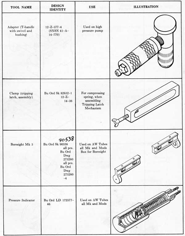
adapter, T-handle
152
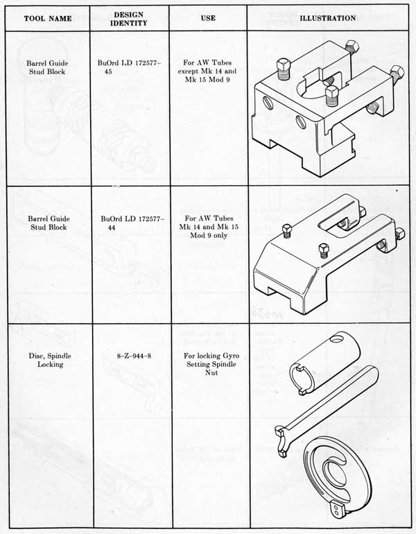
barrel guide stud blocks
151
Boresight Mark 3
152
canvas covers
155-157
clamps
152, 154
cover, hand gun loader
154
disc, spindle locking
151
gage
155
guns, hydraulic grease
154
hose, high pressure hand pump
153
pressure indicator
152
pump mechanism (high pressure)
153
Adapters:
hydraulic
153
T-handle
152
Ammunition:
crane
8
precautions
15, 16, 58
Angles:
gyro
123
offset
123
safe firing
85
sight
123
spread
126
target
124
track
124
Automatic brake. (See Brake, automatic.)
Auxiliary hydraulic pump:
housing
71
screen
72
Auxiliary relief valve:
description and operation
71
Barrels:
adjustment
42
component arrangement
1, 30, 31
data
30
design differences
30
disassembly and reassembly
30
doors
2
fittings
38
heaters
133
lubrication
40
operation
40
maintenance
40
rollers and roller brackets
32, 33
spoon and extension
34, 35
T-guide
34
torpedo stop mechanism
39
tripping latch mechanism
41
Basic setting (See also: Gyro setting mechanism.)
Blast shield:
components
129
design features
129
Blast shield-Continued
Page
disassembly and reassembly
131
installation
131
purpose
129
Boresight:
front sight
124
rear sight
123
operation
124
Brake, automatic:
adjustment
87, 88
assembly, Mk 6
91
assembly, Mk 7
91
disassembly, Mk 6
91
disassembly, Mk 7
91
test
83
Cables, electrical:
installation and maintenance
143
Canvas covers:
illustrations
155-157
Cartridge data
54
Cartridge chamber:
breechblock
48
casting
48
door
48
Centering pin assembly:
components
21
description
21
operation
21
Central pivot cover plate:
components
23
description
23
purpose
23
Chain hoist (See also: Crane, retractable lifting.)
description
1
location
1
use
1
Clutch, hydraulic motor:
purpose
73
type
73
Crane, retractable lifting:
location
1
operation
1
purpose
1, 8
Depth setting mechanism:
adjustment
101
components and arrangement
101
design features and differences
101
disassembly and reassembly
118
lubrication and maintenance
106
operation
105, 108
precautions
108
Door mechanisms:
adjustment
42
components and arrangement
30
disassembly and reassembly
44
162
Door mechanisms-Continued
Page
lubrication and maintenance
40, 41
operation
41
Electric controller:
cable connections
69
case
69
data
70
location
69
type
69
Electric hydraulic drive:
adjustment
86
components
2
data
68, 70
description
66
design features
61
disassembly and reassembly
89
component arrangement
61
maintenance
77
operation
76
tests
83
Electric motor:
connections
67
data
68
lubrication
78
Electrical installation:
description
137
equipment
137
fuses
143
maintenance
142
precautions
143
repair and replacement
143
tests
142
Filter:
cleaning
79
description
73
functional arrangement
73
preservation
79
Firing angles
85
Firing circuit:
checking and testing
142
components
1, 139
functional arrangement
139
Firing control cable
47
Firing mechanism:
adjustment
58
components and arrangement
47
description
47
disassembly and reassembly
48
maintenance
56
operation
55
Firing panel:
bracket
37, 38, 45
components
1
cable connections
139
Firing pin assembly:
cable connection
49, 54
components and arrangement
47
disassembly and reassembly
59
inspection
56
location
49
lubrication access
51
operation
55
Firing pin assembly-Continued
Page
preservation
57
Firing signals:
buzzer or horn
139
Guide blocks
8
Gyro angle drum:
arrangement
123
maintenance
125
operation
125
purpose
125
Gyro setting mechanism:
adjustment
109
components
92
description
92
disassembly and reassembly
114
operation
104
precautions
108
trouble analysis
109
Handwheel mounting bracket:
components
66
lubrication access
67
operation
66
Handwheel trunk:
components
67
function
67
Heating equipment:
arrangement
135
components
4, 133
disassembly and reassembly
136
maintenance
135
purpose
132
type
132
Hydraulic motor:
disassembly and reassembly
89
component arrangement
61, 73
connections
73
description
73
operation
73
purpose
73
type
73
Hydraulic percussion firing controls:
component arrangement
51
operation
55
maintenance
56
receiver assembly
52
transmitter assembly
51
Hydraulic pump (auxiliary):
purpose
71
type
71
Hydraulic pump (main):
component arrangement
70
disassembly and reassembly
90
location
70
operation
70
purpose
70
type
70
Illumination circuit:
purpose
139, 142
Impulse cartridge:
case, type
54
data
54
inspection
56
163
Impulse cartridge-Continued
Page
loading
13
precaution
58
primer
54
stowage, locker
1
Limit stops:
adjustment
86
operation
67
purpose
67
Lubrication:
access
144
adulterants
145
charts
144
cleanliness
145
distribution
145
frequency
145
lubricants
144
preservation
145
reference information
144
Main hydraulic pump (See: Hydraulic pump (main).)
Main relief valve and make-up valve (See: Relief and make-up valve assembly.)
Make-up pump (auxiliary pump):
purpose
71
type
71
Manual percussion firing
55
Misfire
16
Motor controller (See: Electric controller.)
Multiple disc friction clutch:
purpose
73
type
73
Neutral lock valve:
components
72
purpose
72
Operating precautions:
depth setting
108
electrical servicing
143
firing and misfire
13, 16
loading and stowage
8
steam pressure limits (heating)
135
tools
148
training gear
80
Operation, torpedo tube:
barrels and door mechanisms
40
firing mechanism
55
general
7
heating equipment
135
sight
124
torpedo controls
104
training gear
76
Overcurrent relay:
cable connection
137
circuit components
137
operation
139
purpose
139
Percussion firing:
hydraulic (See: Hydraulic percussion firing.)
manual (See: Manual percussion firing.)
Pivot cover plate:
components
23
purpose
23
Power training drive:
Page
adjustment
85
components
61
data
68, 70
description
66
design features
61
disassembly and reassembly
89
component arrangement
61
maintenance
77
operation
76
test instructions
83
Pump housing (reservoir):
disassembly and reassembly
90
components
70
location
70
purpose
61, 70
Pushbutton station:
cable connections
139
location
139
type
139
Relief and make-up valve assembly:
adjustment
87
connections
71
operation
71
purpose
71
Roller assembly, stand and saddle disassembly
and reassembly
27
components
18
maintenance
24
Rollers, barrel, assembly:
adjustment
42
components
30
maintenance
40
purpose
29
Saddle (See: Stand and saddle.)
Safe firing angles
85
Safety precautions:
ammunition
16
operation
15
electrical equipment
80
securing equipment
16
Sight:
adjustment
126
angle
120
disassembly and reassembly
128
boresight
126
components
120
maintenance
125
operation
124
purpose
120
sight angle drum
123
torpedo tube sight
120
type
120
Speed setting mechanism:
component arrangement
103
design features
103
disassembly and reassembly
119
lubrication
107
maintenance
106
operation
106
preservation
108
Spread setting (See also: Gyro setting mechanism.)