LOADING, STOWING AND HANDLING DEPTH CHARGE CASES AND PISTOLS
4.1 Depth Charge Cases Mark 9 and modifications will be filled with cast TNT at loading stations. All cases will be issued for service with the filling hole covers in place and with the ends of the central tubes closed with blanking plates.
LOADING THE CASES
4.2 Loading the Cases. To load a Depth Charge Case Mark 9, Mark 9 Mod. 1 or Mark 9 Mod. 2, place it on its side with the filling hole uppermost. Remove the domed cover, filling hole plate cover, and gasket from the filling hole. Then re-set the filling hole cover cap screws in the holes in the filling hole flange to keep the holes free of TNT. Load a small amount of the charge into the case and turn the case over to allow the charge to solidify around the filling hole. Turn the case back over and load the remainder of the charge into the case. Be sure the case is filled and the charge is free of pockets. Any cavities in the charge may unbalance the case in such a way as to reduce its sinking speed and to increase its dispersion. Clean the filling hole flange. Then remove the cap screws, replace the gasket, and install the filling hole cover. Set the cap screws up evenly and tightly enough to form a watertight joint. Replace the outer domed cover on the filling hole cover.
34
STOWING AND HANDLING THE CASES
4.3 Stowing and Handling the Cases. The Depth Charge Mark 9 and its modifications must be stowed and handled more carefully than depth charge Mark 6 or Mark 7 because the rings or shroud may be damaged by rough handling unless protected by a shipping container. Unprotected Mark 9 charges must be battened down during stowage or shipment to prevent movement. Barrel stowing of uncrated charges is not permitted. Recommended stowage consists of placing the charges upright on the nose or tail in one or two tiers separated by a platform with movement restricted. Rack stowage is approved for horizontal stowage if vertical and horizontal movement is restricted and is not excessive.
4.4 Depth Charge Pistols and Booster Extenders Mark 6 and Mark 6 Mod. 1 are to be loaded, assembled, tested, handled, and stowed as directed in Ordnance Pamphlet No. 747 (First Revision).
4.5 Depth Charge Pistols Mark 7 Mod. 1 contain detonator and booster charges and, therefore, must be handled and stowed as live ammunition. Rough handling of the pistol, in or out of its shipping and stowing container, or in an assembled depth charge, should be avoided. Special stowage lockers for these pistols are required. These pistols are not to be stowed in the same compartment with other explosives. Pistols not immediately required for use with depth charges in the track or projector should be stowed in their sealed containers in these lockers. Sufficient empty containers should be retained for the stowage of pistols temporarily removed from depth charges stowed on deck.
4.6 The Depth Charges Pistol Mark 7 Mod. 1 is loaded and assembled at the loading depot. It is not to be tested or disassembled after issue.
35
INSTALLING PISTOL INTO THE CASE
CHAPTER 5
DEPTH CHARGE PISTOL MARK 6 MOD. 1
5.1 Depth Charge Pistol Mark 6 or Mark 6 Mod. 1 If a Depth Charge Mark 9 or its modification is to be assembled with a Depth Charge Pistol Mark 6 or Mark 6 Mod. 1 and Booster-Extender Mark 6 or Mark 6 Mod. 1 (including the accompanying detonator and booster), these parts shall be installed as directed in O.P. 747 (First Revision), assembling the pistol, however, in the forward end of the case.
DEPTH CHARGE PISTOL MARK 7 MOD. 1
5.2 Depth Charge Pistol Mark 7 Mod. 1. Prior to installation, the Depth Charge Pistol Mark 7 Mod. 1 should be kept in a Safe condition by a flat safety fork sealed in place and by setting the dial on Safe. When pistols are to be placed in charges to be used in projectors, the seals on the shipping safety forks should be broken and short lanyards attached to the forks for stripping by hand immediately prior to firing the projector.
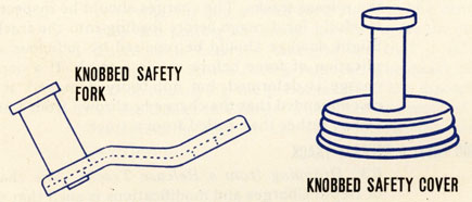
5.3 When pistols are to be placed in charges to be used in the tracks, the shipping safety fork of the pistol is replaced by a knobbed safety fork which is supplied in the pistol container with the pistol. When the charge is dropped from the track, the knobbed fork will be stripped off by the track wiping plate.
5.4 Before installing the pistol in the case, check the pistol to see that (a) it is cocked (the letter C showing in the inspection port), (b) a safety fork is in place on the pistol, (c) the depth-setting dial is set as S (safe). Prepare the case by removing the blanking plate and the wide shipping gasket from the nose end of the central tube (opposite the fins). See that a blanking plate is installed on the after end of the central tube with a gasket between the plate and the flange of the tube. Make sure the cap screws securing this plate are tight enough to form a water-tight joint.
36
DEPTH CHARGE CASE MK, 9 OR MK, 9 MOD, 1 WITH PISTOL MK, 6 OR MK, 6
MOD, 1 AND BOOSTER EXTENDER MK, 6 OR MK, 6 MOD, 1
37
DEPTH CHARGE CASE MK, 9 MOD, 2 WITH DEPTH CHARGE PISTOL MK, 7 MOD, 1
38
DEPTH CHARGE PISTOL MARK 7 MOD. 1
39
5.5 Place the narrow gasket, which was supplied in the pistol container with the pistol, over the body of the depth charge pistol and seat it on the pistol flange. Insert the pistol in the nose of the central tube and secure it with cap screws and washers. Set the screws up evenly and tightly so that a watertight joint will be formed between the pistol and the central tube flange.
5.6 The employment of a light slushing compound on the pistol face is recommended to minimize corrosion. Do not use excessive quantities of this compound as this may produce sluggish operation of the pistol.
5.7 Uncertain operation of the Depth Charge Pistol Mark 7 Mod. 1 may be expected at temperatures of 20 F. or lower because of icing in the pistol inlet ports. Therefore, when temperatures this low are experienced or expected, it is suggested that an antifreeze mixture of 2/3 glycerin and 1/3 alcohol be placed in the pistol through the ports under the anticountermining ring. Enough anti-freeze mixture should be inserted to allow slushing of all parts, but it is not necessary to fill the chamber completely nor to seal the pistol against leakage of the anti-freeze mixture. Caution: The pistol must be set on Safe during this operation.
5.8 Because Depth Charge Pistols Mark 7 Mod. 1 contain detonator and booster charges, any pistol which becomes armed prematurely shall be considered dangerous. The condition of a pistol may be seen, before it is assembled in a depth charge, by the letter showing in the inspection port of the sub-booster carrier. The letter C indicates that the pistol is cocked and safe. The letter A indicates that it is armed and dangerous. The condition of a pistol already assembled in a depth charge can be noted by the position of the outer end of the piston rod
40
with relation to the anti-countermine valve. If the piston rod protrudes through the valve so that a safety fork may be placed. on it, the pistol is safe. If the end of the rod is flush with, or inside, the valve, the pistol is probably armed and must be considered dangerous. DO NOT ATTEMPT TO DISASSEMBLE OR DISARM AN ARMED PISTOL. TO DO SO MAY CAUSE AN EXPLOSION OF THE DETONATOR AND BOOSTER CHARGES. Any pistol which has become armed, or is damaged so that it might become armed, should be destroyed. The pistol may be removed from a depth charge by removing the cap screws securing it in the central tube and pulling the pistol gently out of the tube. Precautions must be taken to see that it is not dropped or struck during removal. The exact manner of destroying the pistol is left to the discretion of the Officer in Charge. The simplest means of accomplishing this at sea is to throw the pistol overboard.
ARMED POSITION
(DANGEROUS)
COCKED POSITION
(SAFE)
41
INSTRUCTIONS FOR USE
CHAPTER 6
INSTRUCTIONS FOR USE OF DEPTH CHARGES MARK 9 AND MODIFICATIONS
6.1 The depth-setting dials of all depth charge pistols should be kept on the SAFE setting at all times until they are adjusted for immediate use. If a charge is accidentally released in this condition it will not fire. When depth-settings are specified by the Commanding Officer, the setting dials may be turned to the desired positions.
6.2 Depth Charges Mark 9 or modifications must be handled carefully to prevent damage to the support rings and shrouds. Any deformation of the rings or shrouds may cause depth charges to jam in the release tracks. The charges should be inspected carefully for damage before loading into the tracks. Slight damage should be repaired by judicious application of force before use in a track. If a depth charge is deformed, but not badly damaged, it is recommended that the charge be thrown from a projector, rather than rolled from a track.
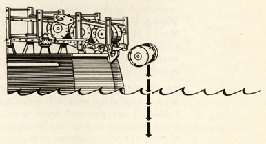
DROPPING FROM A RELEASE TRACK
6.3 Dropping from a Release Track. The shape of Depth Charges and modifications is such that the detents of the release traps of most types of release tracks will not bear against the cases evenly unless the tracks have been modified. The Bureau of
Drawing of depth charge dropping from rack.
42
Ordnance has issued instructions (Bureau of Ordnance Circular Letter No. M5-43) for the modification of release tracks to accommodate Depth Charges Mark 9 and modifications.
6.4 When placing Depth Charges Mark 9 or modifications in a release track, orient them so that the pistol which is assembled in the nose of the case is at the most accessible side of the track (usually the inboard side) to facilitate setting the firing depth of the pistol before the charge is dropped.
6.5 When Depth Charges Mark 9 or modifications assembled with a Depth Charge Pistol Mark 6 or Mark 6 Mod. 1 and a Booster-Extender Mark 6 or Mark 6 Mod. 1 are dropped from a release track, the knobbed cover is stripped from the pistol and the knobbed safety fork is stripped from the booster-extender by the track wiping plates.
6.6 When Depth Charges Mark 9 Mod. 1 or Mark 9 Mod. 2 assembled with a Depth Charge Pistol Mk. 7 Mod. 1 are dropped from a release track, the knobbed safety fork on the pistol is stripped by one of the track wiping plates as the charge is released.
43
FIRING FROM A PROJECTOR
FIRING FROM A PROJECTOR
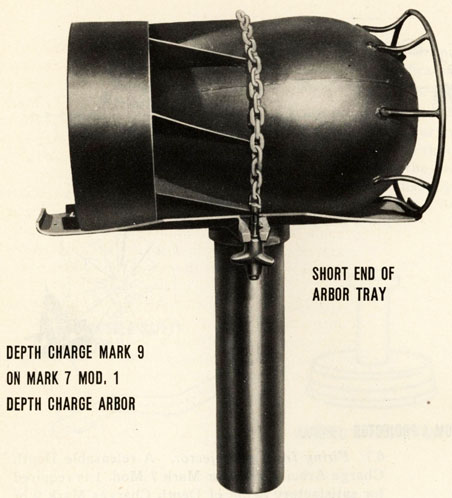
6.7 Firing from a Projector. A releasable Depth Charge Arbor Mark 7 or Mark 7 Mod. 1 is required for satisfactory firing of Depth Charges Mark 9 or modifications from a "K" or "Y" gun projector.
6.8 Because the centers of gravity of Depth Charges Mark 9 and Mark 9 Mod. 1 are relatively near the linear centers of the cases, the offset feature of the Arbor Mark 7 or Mark 7 Mod. 1 is not required. Therefore, when using an Arbor Mark 7 or a Mark 7 Mod. 1 with a Depth Charge Mark 9 or Mark 9 Mod. 1 the charge should be mounted with the center of its length in line with the longitudinal axis of the arbor stem and the stop in position marked "Unweighted charges" on the longer end of the arbor saddle.
44
Depth Charge Mark 9 On Mark 7 Mod. 1 Depth Charge Arbor
6.9 The center of gravity of the Depth Charge Mark 9 Mod. 2 is about 11 to 11-1/2 inches from the nose. In this case the offset feature of the arbor is required, and the charge must be mounted with the nose against the stop in position marked "Weighted Charges" on the shorter end of the arbor saddle.
6.10 A depth charge may be secured in the arbor either before or after the arbor is placed in the projector. Secure the charge in the arbor as follows:
(a) See that the movable stop is on the proper
end of the arbor saddle for the type of charge
being loaded (see pars. 6.8 and 6.9).
45
(b) Place the charge on the arbor. If the charge is a Mark 9 or Mark 9 Mod. 1, the orientation of the charge in the saddle is unimportant with the stop in correct position. If the charge is a Mark 9 Mod. 2, it must be placed in the arbor with the nose support ring against the movable stop in position on the shorter end of the arbor saddle.
(c) Place the securing chain or cable around the charge. See that the latch release in the chain or cable is properly assembled, with a shear pin installed. The shear pin will keep the release mechanism latched until the projector is fired.
(d) Place the adjusting stud of the chain or cable in its bracket and tighten the securing nut until the charge is held firmly in the saddle. The securing nut is threaded at one end only. The nut should be placed on the stud threaded end first.
6.11 When the charge and arbor are placed in a projector, the link on the end of the release mechanism chain should be slipped through the sea lashing hook on the barrel of the projector so that it will hold when the charge is fired. The sudden strain on the chain from firing will shear the pin and allow the release mechanism to operate. Unless the projector is to be fired immediately, the charge and arbor should be lashed to the lashing hooks on the projector with either three turns of spun yarn (minimum breaking strength-305 pounds) or five turns of Navy marline (minimum breaking strength-175 pounds). The lashing need not be cut before firing the projector. The arbor release mechanism should be kept well greased as a precaution against corrosion which might prevent the mechanism from releasing when fired.
46
GENERAL ARRANGEMENT
47
48
Depth Charge Mark 9 Mod. 2 On Depth Charge Arbor Mark 7 Mod. 1
6.12 If the depth charge is assembled with a Depth Charge Pistol Mark 6, or Mark 6 Mod. 1, and a Booster Extender Mark 6, or Mark 6 Mod. 1, knock the knob off the pistol cover with a depth setting wrench, or other instrument, and pull the safety fork off the booster-extender with the lanyard by hand immediately before firing the projector.
6.13 If the depth charge is assembled with a Depth Charge Pistol Mark 7 Mod. 1, remove the safety fork with the lanyard by hand immediately before firing the projector.
49
OPERATIONAL CHARACTERISTICS
CHAPTER 7
OPERATIONAL CHARACTERISTICS OF DEPTH CHARGE MARK 9 AND MODIFICATIONS
LAUNCHING SPEEDS
7.1 Launching Speeds. Table 2 gives the sinking speeds of the depth charges and the minimum safe speed of the launching vessel in deep water for shallow depth settings of these charges.
TABLE 2
MK. 9, MK. 9 MOD. 1 OR MK. 9 MOD. 2 FITTED WITH A 15 FT. SEC. SPOILER PLATE
MK. 9 MOD. 2 WITH SPOILER PLATE
MK. 9 MOD. 2
Sinking speed (terminal)
14.5 ft./sec.
20 ft./sec.
22.7 ft./sec.
Sinking time (stern launched) to:
30 ft.
2-1/4 secs.
2-1/4 secs.
2-1/4 secs.
50 ft.
4 secs.
3-1/2 secs.
3 secs.
100 ft.
7-3/4 secs.
6 secs.
5-1/4 secs.
150 ft.
11 secs.
8-1/2 secs.
7-1/2 secs.
Minimum safe speed for depth setting of:
30 ft.
13 knots
17 knots
20 knots
50 ft.
9 knots
11 knots
13 knots
100 ft.
4 knots
5 knots
6 knots
150 ft.
2 knots
2-1/2 knots
3 knots
7.2 The minimum speeds given in Table 2 apply for dropping single charges. There is reason to believe that some cumulative damaging effect may
50
result from a pattern in which two or more depth charges detonate within a very small time interval. No data are available at present which will enable determination of this effect and the recommendation of definite speeds. It is not believed that the increase in speed for firing patterns is very great, unless the pattern is such that there is a probability of several charges going off simultaneously.
7.3 In water under 100 feet deep, the damaging effects of shallow shots may be accentuated by reflections from the bottom. It is recommended, therefore, that the minimum speeds be increased by 2 knots when dropping depth charges in shallow water.
7.4 The data of Table 2 are values estimated on the basis of information currently available. Both the minimum safe launching speeds and the charge sinking times are on the conservative (fast) sides. The minimum safe speeds as tabulated are for normal conditions and are specified to protect the ship from structural damage or severe shock damage, but recognizes the possibility of minor damage and electrical shock troubles which will not permanently immobilize the ship or seriously impair her activities. In practice attack for depth charge test, the launching speed should be at least 2 knots greater.
EXCEPTIONS TO MINIMUM SPEEDS OF TABLE 2
7.5 Exceptions to minimum speeds of Table 2. It may be desirable under favorable conditions to risk the firing ship by dropping depth charges at slower speeds if the situation is such that this is necessary to deliver a promising attack against an enemy submarine. Under abnormal conditions (rough weather and heavy seas, ship structurally damaged, or in shallow water) somewhat higher minimum speeds should be adopted to avoid damage to the firing
51
ships. The amount of speed margin to allow in each case must be determined by the Commanding Officer, taking into consideration the degree of abnormality of conditions.
PISTOL FIRING DEPTHS
7.6 Pistol Firing Depths. The Depth Charge Pistol Mark 6 Mod. 1 was originally designed for use in Depth Charges Mark 6 or 7 which do not sink as fast as Depth Charges Mark 9 and Modifications. Unfortunately, the faster sinking charges do not permit sufficient time for the water chamber of these pistols to fill for firing at shallow depth.
7.7 Table 3 shows the depths at which Depth Charge Pistols will probably fire when used in Depth Charges Mark 9 and modifications. There may be a considerable variation from the figures given, as the actual firing depth is determined by the rate of entry of water into the pistol.
TABLE 3
ACTUAL FIRING DEPTH AND TIME IN CASE
MK. 9 OR 9-1
MK. 9-2 (22.7 FT/SEC.)
PISTOL
PISTOL SETTING
DEPTH FT.
TIME SEC.
DEPTH FT.
TIME SEC.
Mk. 6
30
45
3-3/4
60
3-1/2
50
60
4-1/2
80
4-1/2
75
80
6
90
4-3/4
100
100
7-3/4
105
5-1/2
Mk. 6-1
30
85
6-3/4
110
5-3/4
50
95
7-1/4
130
6-1/2
75
100
7-3/4
140
7
100
125
9-3/4
145
7-1/4
150
150
10-1/2
165
8-1/4
Mk. 7-1
50
50
4
55
3-1/2
100
100
7-3/4
100
5-1/4
52
7.8 The Depth Charge Pistol Mark 7 Mod. 1 (to be used only in the Depth Charges Mark 9 Mod. 1 or Mark 9 Mod. 2) will fire within its tolerance at the set depth.
PROJECTION RANGES
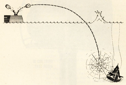
7.9 Depth Charges Mark 9 and modifications may be fired safely from side projectors at any speed with the No. 1 impulse charge, provided that the impulse charge does not give less than 30 yards range for any reason such as excessive rolling or improper performance of the charge. Table 4 gives the normal ranges and estimated times of flight of the Depth Charges Mark 9 and modifications when fired from projectors.
TABLE 4
IMPULSE CHARGE
RANGE
ESTIMATED TIME OF FLIGHT
#1
60 yds.
3.4 seconds
#2
90 yds.
4.2 seconds
#3
150 yds.
5.1 seconds
7.10 The information contained in this chapter on minimum safe launching speeds is based upon information furnished by the Bureau of Ships.
53
APPENDIX A
DRAWINGS PERTAINING TO DEPTH CHARGES MARK 9 AND MODIFICATIONS
LIST OF DRAWINGS SKETCH NUMBER
GENERAL ARRANGEMENT DRAWINGS NUMBER
(a) Mk. 9-
(1) Depth Charge Assembly
55553
362685
(2) Case
55478
Sk. 112173
(b) Mk. 9 Mod. 1-
(1) Depth Charge Assembly
Mu.Sk. 25789
(2) Case
130645
383906
(c) Mk. 9 Mod. 2-
(1) Depth Charge Assembly
(2) Case
130590
383781
(d) Depth Charge Pistol-
(1) Mk. 6
204044
(2) Mk. 6 Mod. 1
328372
(3) Mk. 7 Mod. 1
109978-79
383706
(e) Booster Extender-
(1) Mk. 6
204053
(2) Mk. 6 Mod. 1
328206
(f) Booster--
(1) Mk. 6
204056
(2) Mk. 6 Mod. 1
375783
(3) Mk. 6 Mod. 2
388788
(g) Releasable Arbor-
(1) Mk. 7
375995
(2) Mk. 7 Mod. 1
388799
(h) Depth Setting Wrench
389143
54
DISTRIBUTION
Requests for copies of OP 866 (1st Revision) should be addressed to the nearest BuOrd Publications Distribution Center:
Commandant and Superintendent
U. S. Naval Gun Factory, Navy Yard
Washington 25, D.C.
(Attn: OrdPubSubcen)
Commandant
Navy Yard
Mare Island, California
(Attn: OrdPubSubcen)
Commander Service Force, SEVENTH FLEET
Ordnance Publications Subcenter
c/o Fleet Post Office
San Francisco, California
Officer in Charge
Ordnance Publications Subcenter
Naval Supply Depot
Pearl Harbor, T. H.
DISTRIBUTION:
Standard Navy Distribution List No. 20
2 copies each unless otherwise noted.
1.a-e,g,h,k,l,q-t,x,z-ff,ii,ll,mm,pp,ss,tt,ww,xx,zz;2.a
(Torpedo, Observation, Cruiser, Scouting & Patrol Rons only),b,c,e(CruDivs only),g,h,k,n,q,r,v ; 3.(1 copy),nn; 3.i,j,k,m,r,rl,w,y,cc; E3.; 4.(1 copy),nn; 4.i-k,m,r,w,y,cc; 5.b(Alusna,London only); 6.a-n; 7. b,c(NOB's only),f-i,p(NAD's only),r,s,u(except Naval Clothing Depot),aa,ee(Advance Base Depots only); 7.(5 copies),a(Navy Yds. only),1(DesBases only); 8.a(San Diego only),b,h(NOL and No. Beach only),i,j(except Panama City, Fla. and Neah Bay, Wash.),n(SPECIAL LIST G,K,L,P,V,AA); 10.t; 10.(25 copies),nn; 11.a(BuShips),ComdtMarCorps; 12.a,b(Revision 1); 14.a,q.