This publication is RESTRICTED and will be handled in accordance with Article 16, United States Navy Regulations, 1920
2
This page is blank.
3
NAVY DEPARTMENT
BUREAU OF ORDNANCE
WASHINGTON, D. C.
12 February 1944
RESTRICTED
ORDNANCE PAMPHLET NO. 866 (FIRST REVISION)
DEPTH CHARGE MARK 9 AND MODIFICATIONS - DESCRIPTION AND INSTRUCTIONS FOR USE.
1. Ordnance Pamphlet No. 866 (First Revision) contains a description and instructions for use of the Mark 9, Mark 9 Mod. 1 and Mark 9 Mod. 2 Depth Charges.
2. This publication supersedes Ordnance Pamphlet No. 866, which should be destroyed.
3. It is not intended that this publication be carried in aircraft for use therein.
4. This publication is RESTRICTED and is to be handled
in accordance with the provisions of article 76, Navy Regulations,
1920.
1.1 Depth Charges Mark 9 and modifications are teardrop shaped, anti-submarine weapons which have higher sinking speeds and more stable underwater flight characteristics than the cylindrical, symmetrically-loaded Depth Charges Mark 6 and Mark 7 and modifications. These improved characteristics permit greater attack accuracy than has been possible in the past.
1.2 In order to launch these teardrop shaped charges from existing tracks, it is necessary to modify most tracks in accordance with Bureau of Ordnance Circular Letter M5-45 so that the pawls and detents will control the charges.
1.3 To project these charges from a projector, it is necessary to use an arbor which will separate from the depth charge after the projector is fired to take advantage of the characteristic underwater trajectory and sinking speed of the charge. Depth Charge Arbors Mark 7 and Mark 7 Mod. 1 were designed for this purpose.
1.4 There are three streamlined, teardrop shaped depth charges, the Mark 9, Mark 9 Mod. 1 and Mark 9 Mod. 2. Table 1 summarizes pertinent information regarding these charges.
1.5 Depth Charge Pistols Mark 6 and Mark 6 Mod. 1 are the only pistols suitable for use in the Depth Charge Mark 9. Depth Charge Pistols Mark 6, Mark 6 Mod. 1, or Mark 7 Mod. 1 may be used in Depth Charges Mark 9 Mod. 1 and Mark 9 Mod. 2. In all instances, the pistol is mounted in the nose of the depth charge case, and the Depth Charge Booster-Extender Mark 6 or Mark 6 Mod. 1, which is used with the Pistol Mark 6 or Mark 6 Mod. 1, is placed in the aft end of the charge case.
8
DEPTH CHARGE MARK 9 MOD, 1
9
DEPTH CHARGE MARK 9 MOD, 2
10
DEPTH CHARGE MARK 9 MOD, 2 WITH SPOILER PLATE
11
SPOILER PLATE
1.6 The performance characteristics and physical outline of the Depth Charge Mark 9 Mod. 1 do not differ from those for the Depth Charge Mark 9. (The Depth Charge Case Mark 9 Mod. 1 is fabricated differently than the Depth Charge Case Mark 9.) It is to be noted that the faster sinking Depth Charge Mark 9 Mod. 2 can be distinguished easily from the other charges by means of its straight fins and the substitution of two rings for the tail shroud that appears on the Depth Charges Mark 9 and Mark 9 Mod. 1 It is important that the Depth Charge Mark 9 Mod. 2 be recognized due to its faster sinking speed and the resulting greater launching speed required for the launching vessel when this charge is stern dropped and set to fire at shallow depths. (See Chapter 7 for launching speed tables.)
1.7 In situations where the advantage of high sinking speed of the Depth Charge Mark 9 Mod. 2 is desired but where the launching speed requirements cannot be met, spoiler plates are used to reduce the sinking rate of this charge from 22.7 ft./sec. to 20 or to 15 ft./sec. These spoiler plates are fastened to the nose of the case over the pistol using the pistol cap bolts.
Pages 12 and 13
TABLE 1
DEPTH CHARGE CASE
CASE DETAILS
CASE WGT. (EMPTY)
EXPLOSIVE CHARGE WEIGHT
PISTOL
PISTOL DEPTH SETTING RANGE (FT.)
BOOSTER- EXTENDER
ASSEMBLED OVERALL WEIGHT
AVERAGE TERMINAL SINKING SPEED
MK. 9
(1) 8 fins set at 20
90 lbs.
200 lbs. TNT
Mk. 6 Mk. 6-1
30 - 300 30 - 600
Mk. 6 Mk. 6-1
320 320
14.5
(2) 6" shroud on tail
(3) Nose ring of round mat'l.
(4) Fore and aft welded case.
MK. 9 MOD. 1
(1) Stamped case welded circumferentially
90 lbs,
200 lbs. TNT
Mk. 6 Mk. 6-1 Mk. 7-1
30 - 300 30 - 600 50 - 500
Mk. 6 Mk. 6-1
320 320 310
14.5
(2) Other details same as above.
MK. 9 MOD. 2
(1) Stamped case
120 lbs.
190 lbs.
Mk. 6
30 - 300
Mk. 6
340
22.7, 20.0* or 15*
(2) 8 fins set at 3
TNT
Mk. 6-1 Mk. 7-1
30 - 600 50 - 500
Mk. 6-1
340 330
(3) 2 tail rings & 1 nose ring made of oval mat'l.
(4) 40 lbs. lead inside nose.
* Sinking speeds with spoiler plates attached to the case nose.
14
DEPTH CHARGE CASE MARK 9
15
DESCRIPTION
CHAPTER 2
DESCRIPTION OF DEPTH CHARGE CASES MARK 9 AND MODIFICATIONS
2.1 The Depth Charge Mark 9 or its modifications consists of a depth charge case, a depth charge pistol, and an appropriate depth charge booster-extender as necessary.
2.2 Depth Charge Case Mark 9 has a maximum length of 27.625 inches and a maximum diameter of 17.640 inches. A support ring, 1/2-inch-diameter, is secured to the nose or forward end of the case by eight brackets. Eight fins are secured along the after end and are set at an angle of 20 degrees to the longitudinal axis of the case. The rotation of the case as it sinks is due to the fins and improves the underwater trajectory. A shroud or support band is fastened to the outer edges of these fins. When the depth charge is installed in a release track, its weight is carried by the support ring and shroud resting on the lower rails of the tracks.
FILLING HOLE
2.3 A filling hole is provided in the side for loading the explosive charge into the case. A flat steel plate is secured to the flange of the hole after the case is loaded, and a domed cover is then secured to this plate. The domed cover has the same contour as the case to preserve the continuity of the stream-lining. A central tube, approximately 24.750 inches long and 4.175 inches inside diameter, extends through the length of the case.
DEPTH CHARGE CASE MARK 9 MOD. 1
2.4. Depth Charge Case Mark 9 Mod. 1 differs from the Depth Charge Case Mark 9 only in the details of construction. The case is of stamped shell construction which is welded circumferentially rather than the "orange peel" fabrication welded fore and aft. None of these changes has any effect on the handling, operation, or characteristics of the depth charge.
16
17
THE CASES
DEPTH CHARGE CASE MARK 9 MOD, 2
DEPTH CHARGE CASE MARK 9 MOD. 2
2.5 Depth Charge Case Mark 9 Mod. 2 differs from the Depth Charge Case Mark 9 chiefly in that the tail shroud is replaced by two rings and the angle of the fins to the longitudinal axis of the case has been reduced from 20' to 3'. The tail rings, the nose ring and nose ring supports have been made oval in cross section to reduce water resistance. The loading hole has been redesigned to facilitate loading the case. The nose of the depth charge case is weighted with 40 pounds of lead. These changes give the Depth Charge Mark 9 Mod. 2 a terminal sinking velocity considerably greater than that of the Depth Charges Mark 9 and Mark 9 Mod. 1.
18
DEPTH CHARGE PISTOL MARK 6 MOD. 1 ASSEMBLED
19
PISTOLS
CHAPTER 3
DEPTH CHARGE PISTOLS, MK. 6 AND MK. 6 MOD. 1
DEPTH CHARGE BOOSTER EXTENDER MARK 6
DEPTH CHARGE PISTOLS MARK 6 AND MARK 6 MOD. 1
3.1 Depth Charge Pistols Mark 6 and Mark 6 Mod. 1 A description of and instructions for testing Depth Charge Pistols and Booster Extenders Mark 6 and Mark 6 Mod. 1 are contained in O.P. No. 747 (First Revision). Refer to this publication if these mechanisms are to be used.
20
GENERAL ARRANGEMENT
DEPTH CHARGE PISTOL MARK 6
21
DEPTH CHARGE PISTOLS, MK. 6 AND MK. 6 MOD. 1
DEEP FIRING MECHANISM DEPTH CHARGE PISTOL MK. 6 MOD. 1
TOP OF DEPTH CHARGE PISTOL MARK 6 MOD. 1
22
DEPTH CHARGE PISTOL MARK 7 MOD, 1
23
DEPTH CHARGE PISTOL MARK 1 MOD. 1
TOP OF DEPTH CHARGE PISTOL MARK 7 MOD, 1
3.2 The Depth Charge Pistol Mark 7 Mod. 1 is a complete primary explosive unit containing detonators and boosters. This pistol must be handled as live ammunition and shall not be disassembled or tested in any way after issue. No accessories are required with the Depth Charge Pistol Mark 7 Mod. 1 for hydrostatic firing.
3.3 The pistol is designed to arm at a depth of approximately 45 feet by hydrostatic action. It may be set to operate as follows:
(a) For firing at predetermined depth between 50 and 500 feet.
(b) On Safe so that it will not arm or fire at any depth.
3.4 A dial set into the pistol flange adjusts the depth setting at which the pistol operates. An arrow scribed in the flange at the outer edge of the dial
24
DEPTH CHARGE PISTOL MARK 7 MOD, 1
25
DEPTH CHARGE PISTOL MARK 1 MOD. 1
indicates the setting of the pistol. Figures scribed on the dial indicate the depths in feet at which the pistol may be fired by hydrostatic pressure.
3.5 The dial can be rotated to the desired position by lifting the knurled knob and turning the dial to match the arrow and figure. The dial should then be locked in place by permitting the knob to seat. When the dial is turned so that the arrow points to the letter M, the pistol can arm but will not be fired by hydrostatic pressure. When the arrow points to the letter S (safe), the pistol is locked so that it will not arm or fire under any conditions.
3.6 A depth-setting wrench will be issued to facilitate setting Depth Charge Pistols Mark 7 Mod. 1 which become difficult to set by hand. This wrench has a claw which fits under the knurled knob of the depth-setting dial locking pin, a socket which fits over the fixed pin protruding from the dial on the opposite side, and a T-shaped handle. To use the wrench, slip the forked claw under the locking pin knob, then push the socket down over the fixed pin. This will pull the locking pin out and allow the setting dial to be turned with the wrench handle.
3.7 As long as a safety fork is in place on the pistol, or the pistol is set at safe, inward motion of the piston rod is prevented and the pistol is locked safe. In this position the explosive train contained in the detonator plunger and sub-booster carrier, which is composed of tetryl lead-in charges from the
26
SECTIONAL VIEW DEPTH CHARGE PISTOL MARK 7 MOD, 1
27
DEPTH CHARGE PISTOL MARK 1 MOD. 1
detonators to the booster, is interrupted by misalignment of these elements. Furthermore, the firing pin is held away from the percussion detonator. Since both the electric and the percussion detonators must fire through the same tetryl leads to set off the sub-booster, firing of either detonator will not set off the sub-booster or booster.
HOW IT WORKS
3.8 How the Depth Charge Pistol Mark 7 Mod. 1 Works. The depth charge is dropped or thrown overboard. At the same time the safety fork on the pistol is wiped or pulled off and the pistol is free to operate by hydrostatic action. As the charge sinks, water enters the pistol through ports inside the depth setting dial and flows into the space inside the bellows, flange, and depth-setting spring retainer.
FIRING PIN AND PERCUSSION DETONATOR
(SECTION 90° FROM SECTION SHOWN ON PAGE 26)
28
TOP VIEW OF DEPTH CHARGE PISTOL MARK 7 MOD. 1
29
DEPTH CHARGE PISTOL MARK 1 MOD. 1
3.9 The pistol is armed by hydrostatic pressure upon the bellows which forces the piston and piston rod to move inward. The motion of the piston compresses the shifting spring between the piston and the detonator plunger. When the piston has moved approximately 1/4-inch, the locking balls in the sub-booster carrier (which is fixed in position by the main spacer tube) slip out into the enlarged section of the piston. The shifting spring then forces the detonator plunger against a stop in the sub-booster carrier. In this position the tetryl leads in the plunger and carrier are aligned. The pistol is armed as the explosive train is now continuous from detonator to the booster. It cannot be returned to the unarmed position without being disassembled because the locking balls in the enlarged section of the piston are prevented from returning to original position.
3.10 Further inward motion of the piston rod causes a shoulder on the rod to come up against the depth-setting spring. The point at which this occurs is controlled by the position of the depth-setting stop. This, in turn, is determined by the adjustment of the depth-setting dial to other than M or Safe position. As the piston moves inward, the firing pin slides up the firing wedge until it is clear of the high point of the wedge. The firing pin spring then snaps the pin against the percussion detonator, firing the pistol. The hydrostatic pressure required to fire the pistol in this manner is determined by the distance the depth-setting spring must be compressed before the firing pin slides past the end of the firing wedge.
3.11 If the pistol is set on M, mechanical interference of the parts in the pistol after arming will prevent the pin from sliding past the end of the wedge. This prevents the pistol from being fired by hydrostatic pressure.
30
3.12 To prevent this pistol from arming prematurely by shock after the safety fork has been removed, the Depth Charge Pistol Mark 7 Mod. 1 is equipped with an inertia lock. This lock consists of a rocker arm mounted on the inside of the spacer tube. The location of the center of gravity of the rocker arm is such that any shock in the direction which would tend to arm or fire the pistol will cause the arm to fly out and momentarily lock the piston in the safe position. Under normal conditions the rocker arm is held clear of the piston by a light spring.
3.13 To prevent premature mechanical firing of the pistol if an explosion should occur close to the depth charge after it is in the water, an anticountermine valve is fitted over the inlet ports in the depth-setting dial. This valve is held in position over the ports by a ring secured to the dial. It is held away from the ports during normal operation by small springs between the valve and the dial. If a sudden increase in pressure (such as would be caused by an explosion close to the pistol) occurs, the valve is designed to move inward against the pressure of the springs. This closes the ports until the pressure returns to normal. The gradual hydrostatic pressure increase which takes place as the depth charge sinks will not close the ports.
3.14 Safety Measures for the Depth Charge Pistol Mark 7 Mod. 1 The Depth Charge Pistol Mark 7 Mod. 1 is assembled at a loading station with all of its explosive components (detonators, tetryl leads, sub-booster and booster) in place. Therefore it must be handled as live ammunition and shall not be disassembled or tested in any way after it is issued for service. This pistol is to be installed in a depth charge only after the charge has been placed in a
31
DEPTH CHARGE PISTOL MARK 1 MOD. 1
track, projector, or projector rack. A damaged or faulty pistol, or one which becomes armed prematurely, shall be disposed of as suggested in paragraph 5.8.
3.15 The pistol must be checked, prior to assembly of the depth charge, by inspection of the port in the sleeve of the sub-booster carrier. The letters A and C are scribed on the surface of the detonator plunger. When the letter A is visible through the port the pistol is armed. When the letter C is visible through the port, the pistol is cocked and is not armed.
3.16 A Depth Charge Pistol Mark 7 Mod. 1 must never be installed in a depth charge case if the pistol is in the armed condition. An armed pistol should be disposed of as suggested in paragraph 5.8
3.17 After the pistol has been installed in a depth charge, its condition can be determined by noting the position of the exposed end of the piston rod. If a safety fork can be placed on it, the pistol is not armed. Should the pistol become armed as shown by the pistol spindle being flush with the flange body, the pistol should be carefully removed and replaced.
32
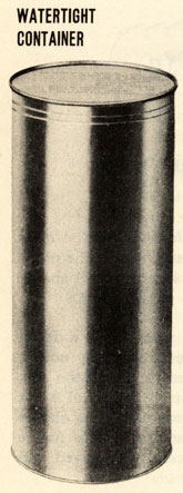
3.18 The Depth Charge Pistol Mark 7 Mod. 1 is loaded and assembled at the loading depot and is issued for service in a cylindrical water-tight metal container with a tear strip for opening around one end. The tear strip may be removed with ordinary pliers by pulling on the exposed metal tab. This allows the pistol to be taken out of the can. The container should not be opened until the pistol is to be installed in a depth charge case. Each pistol will be fitted with a shipping safety fork, secured in place with a wire-and-lead seal. One knobbed safety fork and a pistol flange gasket will be packed in the container with each pistol. In changing from the shipping fork to the knobbed fork care should be taken to set the pistol on Safe in order that the piston rod cannot be pushed inward and arm the pistol accidentally.


 3.6 A depth-setting wrench will be issued to facilitate setting Depth Charge Pistols Mark 7 Mod. 1 which become difficult to set by hand. This wrench has a claw which fits under the knurled knob of the depth-setting dial locking pin, a socket which fits over the fixed pin protruding from the dial on the opposite side, and a T-shaped handle. To use the wrench, slip the forked claw under the locking pin knob, then push the socket down over the fixed pin. This will pull the locking pin out and allow the setting dial to be turned with the wrench handle.
 3.18 The Depth Charge Pistol Mark 7 Mod. 1 is loaded and assembled at the loading depot and is issued for service in a cylindrical water-tight metal container with a tear strip for opening around one end. The tear strip may be removed with ordinary pliers by pulling on the exposed metal tab. This allows the pistol to be taken out of the can. The container should not be opened until the pistol is to be installed in a depth charge case. Each pistol will be fitted with a shipping safety fork, secured in place with a wire-and-lead seal. One knobbed safety fork and a pistol flange gasket will be packed in the container with each pistol. In changing from the shipping fork to the knobbed fork care should be taken to set the pistol on Safe in order that the piston rod cannot be pushed inward and arm the pistol accidentally.