This chapter is a guide to turret operation. It is arranged so that it may aid in organizing the crew. Each crew station is separately described; the equipment used and the duties of the station are defined.* These duties are explained or identified with respect to the functional activities of equipment-a station or compartment-and with respect to methods of control of equipment and of the turret. In the instance of certain key stations, the duties include alternative activities concerning different methods of control or emergency or casualty operations.
Station activities and turret control methods
Classes of operations. All station activities are associated with one of four functional classes of operations. These are:
Ammunition service to the guns
Gun operation
Gun laying
Controlling gun fire
Ammunition service to the guns and gun operation are the same in all methods of turret operation. But the other two classes of operations vary in different methods of remote and local control.
REMOTE CONTROL is a general method of turret control that governs turret fire by electrical signals originating from stations remote from the turret.
LOCAL CONTROL is a general method applying to several variations of control by the turret crew with facilities at hand.
There are eight principal variations of these basic methods of control. They are turret
* Ships should not consider the descriptions of duties of turret personnel to be rigid or definitive. Variations therefrom are within the discretion of the operating forces, provided existing regulations are observed.
fire control selections identified by the following terms:
PRIMARY SURFACE CONTROL
PRIMARY AA CONTROL
SECONDARY SURFACE CONTROL
SECONDARY AA CONTROL
LOCAL RADAR CONTROL
LOCAL SIGHT CONTROL
HI-TURRET CONTROL
HAND (EMERGENCY) CONTROL
PRIMARY SURFACE CONTROL is a remote control method employed against surface targets. It is turret control by a main director in combination with main plotting room equipment. It has two variants: "automatic" and "indicating." In the automatic variation, the turret is controlled without crew assistance. The other directs the crew in "follow-the-pointer" operation. In both variants, the guns are fired by remote switch at the controlling director.
PRIMARY AA CONTROL is a remote control method employed against air-borne targets. It is turret control by a main director in combination with main plotting room equipment. It includes "automatic" and "indicating" variations as in Primary Surface Control. In both variations, it provides automatic fuze setting. In Primary AA Control, all guns are fired by remote switch at the Controlling director.
SECONDARY SURFACE CONTROL is a remote control method that is identical to Primary Surface Control, except for the controlling director. It employs a secondary battery director in combination with main plotting room equipment, routing signals via secondary plot.
SECONDARY AA CONTROL is a remote control method that is identical to Primary AA Control except for the controlling director. It employs a secondary battery director in combination with main plotting room equipment, routing signals via secondary plot.
71
Crew Name
Station
Location
Turret Officer
Right Turret Control
Turret Officer's Booth
Turret Captain
Left Turret Control
Talker: JE (Computer To Sight Setter)
Computer
Talker: JW (Radar Range)
Radar
Talker: JW (Local Computer)
Computer
Computer Operator
Computer
Radar Operator
Left Radar
Radar Operator
Right Radar
Electrician
Roving
Gun Captain*
Right Gun Control Panel
Gun Captain*
Center Gun Control Panel
Gun Cap-Ain*
Left Gun Control Panel
Gun Captain's Assistant**
Roving
Gun Captain's Assistant**
Roving
Trainer
Train Control Handwheel
Right Sight Station
Sight Setter
Sight Setting Indicator
Pointer
Elevating Control Handwheel
Left Sight Station
Checker
Left Sight (Drill Fire Only)
Outer Ring Operator
Outer Ring Control Handwheel
Upper Projectile Flat
Inner Ring Operator***
Inner Ring Control Handwheel
Projectile Man •
Right Steady Arm Mechanism
Projectile Man •
Center Steady Arm Mechanism
Projectile Man •
Left Steady Arm Mechanism
Parbuckler •
Right Gypsy Head
Parbuckler •
Center Gypsy Head
Parbuckler •
Left Gypsy Head
Outer Ring Operator
Outer Ring Control Handwheel
Lower Projectile Flat
Inner Ring Operator
Inner Ring Control Handwheel
Projectile Man
Right Steady Arm Mechanism
Projectile Man
Center Steady Arm Mechanism
Projectile Man
Left Steady Arm Mechanism
Parbuckler
Right Gypsy Head
Parbuckler
Center Gypsy Head
Parbuckler
Left Gypsy Head
Electrician
Roving
Petty Officer In Charge
Hoist Communications
Powder Handling Room
First Powderman, Right
Right Powder Hoist
Second Powderman, Right
Right Powder Hoist
Third Powderman. Right
Magazine Scuttle
First Powderman, Center
Center Powder Hoist
Second Powderman. Center
Center Powder Hoist
Third Powderman, Center
Magazine Scuttle
First Powderman. Left
Left Powder Hoist
Second Powderman, Left
Left Powder Hoist
Third Powderman. Left
Magazine Scuttle
* And Ammunition Supply Talker
** Goes Out On Gun Girder Only When Specifically Directed By Turret Officer: Returns Immediately Upon Completion Of Assignment
*** And Transfer Switch Man
• Emergency Gun Layers (Any Two): For Right And Center Forward Gun Pit Stations: Emergency Gun Layer For Left Gun Pit Station Is Assigned From The Gun House Crew, The Only Access To The Station Being Via The Left Shelf Plate Hatch
General Notes:
1. Projectile Men And Parbucklers Will Alternate
2. When Emergency Elevating Controls Are Manned. Upper Flat Ammunition Handlers Are Assisted By Lower Flat Crew, After Lower Flat Ammunition Is Exhausted
3. Stations Underscored Are Manned By The Condition Watch
Figure 64. Turret Personnel Organization
72
LOCAL RADAR CONTROL is a local control method available to turrets II and III, for use against a surface target. It is independent turret control, deriving target bearing and range by turret radar equipment. It controls the turret train drive in automatic operation, and the gun laying drives in pointer target sighting control. It fires all guns by a designated local switch.
LOCAL SIGHT CONTROL is a local control method available to all turrets for use against surface targets. It is independent turret control, deriving target bearing and range by any available telephone communication or by visual estimate, locally. It controls turret train and gun laying by target sighting control. It fires all guns by designated local switch or switches.
HAND (EMERGENCY) CONTROL is a local control method available to all turrets for use against surface targets. It is independent gun laying control. It derives target bearing and range by any available communication or locally by visual estimate. It controls turret train by target sighting control. It controls gun laying by separate control of each elevating drive. It fires all guns by pointer target sighting control.
HI-TURRET CONTROL is a remote control method for controlling turret I against a surface target. It provides "automatic" or "indicating" control of turret I by gun order transmission from turret II; turret II transmits these orders automatically while operating in Local Radar Control. It requires supplementary telephone transmission of sight and parallax data. Hi-Turret Control is an approximation of Primary Surface Control.
Objectives. In all operations and in each method of control, the primary purpose of the new turret design is to increase the rate and accuracy of fire in comparison with equivalent installations of earlier heavy cruisers; and, secondary, to attain this rapid continuous fire with safety. Both safety and rapidity of equipment actions are design features of the hoists, guns, gun laying drives, and all control arrangements. But speed and safety are dependent in large measure on crew teamwork, alert, smart operation, and good maintenance. These personnel factors can be obtained best by understanding the station equipment, the turret
installations, and the crew arrangement; and by drilling each member of the crew in his duties.
Firing cycle
The significance of turret rapid fire and the importance of teamwork in the ammunition service are indicated by the diagram of figure 63. In continuous automatic fire, each of the three guns of the turret is firing every six seconds. During this period, many ammunition service actions and gun loading actions take place. Most of these actions depend upon completion of a prior action, and the final action, gun firing, is dependent upon smooth coordination and rapid completion of all. Lag or delay in any action will stop or retard gun firing. Figure 63 identifies each action, shows its time interval, together with the period that it overlaps other simultaneous actions, and indicates its dependence on other interlocking movements.
The firing cycle is the key operation of turret rapid fire. Three-fourths of the turret organization directly contribute to its efficient performance, and all other of the crew are indirectly associated, depending on the method of turret control.
Personnel organization
The tabulation of the facing page (figure 64) identifies the members of the turret organization. Forty-four men are required to man the battle stations, and forty-five when training the crew in loading drill and target firing. Twenty-seven men of this complement, located in the levels below the gun house, operate the ammunition service to the guns; six others, stationed in the gun house, control and maintain gun operations; these thirty-three men are identically employed in all methods of turret control.
The balance of the organization consists of two gun laying operators and ten turret control-men, all stationed in the gun house. These twelve men have varying duties, depending on the method of turret control. All are engaged when the turret is locally controlled in drill operations. But when operating under remote control, only one of these men, the sight setter, is actively engaged; all others are at "stand-by': operation. This and other control duty variations are explained in the descriptions of personnel duties starting on page 77.
73
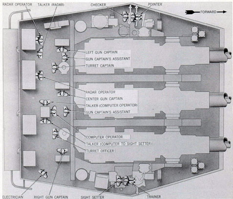
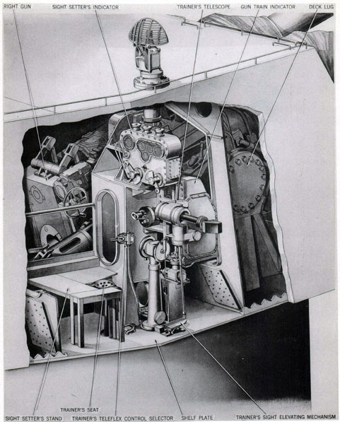
Figure 65. Turret Personnel Arrangement. Gun House Stations
Crew stations
In normal turret operation when the turret is controlled locally or from remote director, crew stations are manned in all levels of the turret except the pan floor. The manned levels are isolated; all intercommunicating hatches are closed and secured. This divides the manned spaces into four compartments with personnel arrangements as illustrated in figures 65 to 68 and as described in the next paragraphs.
Gun house crew. Eighteen members of the crew are located in the gun house as identified in figure 65. Functionally this staff is divided
into three groups. These comprise ten turret controlmen, two gun laying operators, and six gun operators.
The ten turret controlmen are the turret officer, turret captain, computer operator, two radar operators, three talkers, sight setter, and checker. The checker is a member of the crew in training operations only; his station is not manned in battle action.
The two gun laying operators are the pointer and trainer.
The six gun operators are the three gun captains, their assistants, and the electrician. This electrician is stationed in the gun house for
74
general maintenance of the control and communications circuits, but his principal responsibility
is trouble correction and aid in maintaining continuous operation of the guns.
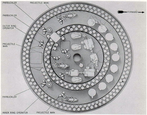
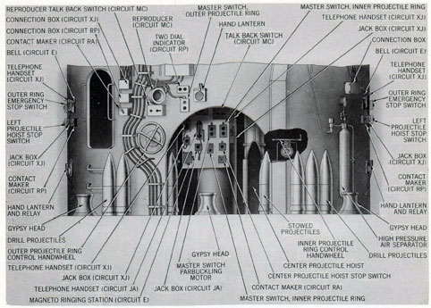
Upper projectile flat crew. Eight members of the turret organization are stationed in the upper projectile flat, three in the inner compartment, two at the rear right and three at the rear left of the outer compartment; all as identified in figure 66. They are all engaged in supplying projectiles to the hoists, the men in the inner compartment exclusively serving the center projectile hoist while the men in the outer space are a team with right and left sections serving the wing hoists and with the ring operator maintaining supply to both.
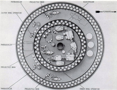
Lower projectile flat crew. Nine men comprise the organization of the lower projectile flat. Their station arrangements are shown in figure 67. Eight members of this group have identical duties to those of the eight men on the flat above. The ninth man is the power-supply electrician and general assistant for maintenance of ammunition service.
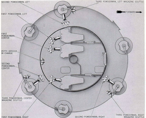
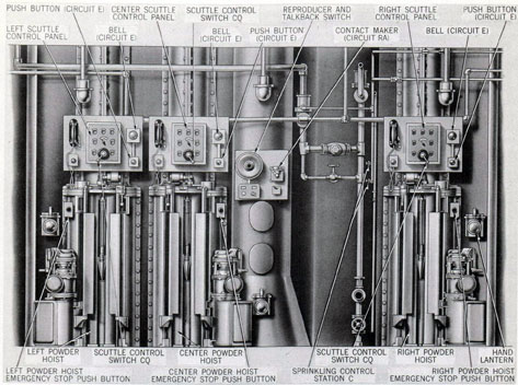
Powder handling room crew. Figure 68 shows the station arrangements of the remainder of the turret organization. Ten men conduct the powder transfer service; three men serve each hoist under supervision of a petty officer.
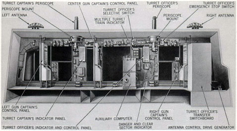
Duties. The turret officer is the supervisor of turret operations. He directs the entire crew. He organizes and trains the operators of all stations for performance of their duties in all types of control. His operations are directed by the control officer, when the turret is to be operated in automatic or indicating control. He sets the turret transfer switchboard and other necessary controls for remote direction and control. His main duties, in either of these methods of control, are: general supervision of turret operation, coordinating and directing the
work of the turret crew, and observing the fall of-shot through the periscope or on the radar screen. He is prepared to take control, in the event of failure of director control, and to direct target firing after shifting to local control.
In local control, the turret officer assumes full control of turret fire, designating the target and directing and coordinating all turret operations. He observes the fall-of-shot through the periscope or on the radar screen, and constantly gives spot correction orders to the computer operator.
Equipment used. The turret officer's control station and the equipment used by him, both at the station and adjacent thereto, are illustrated
77
Figure 69. Turret Officer's Booth. Fire Control
Arrangement. Forward Bulkhead
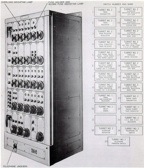
in figures 69 and 70. His major piece of equipment is his transfer switchboard, consisting of 25 rotary switch elements, lights panels, and warning buzzers, used to route electrical control signals from the plotting room in control of the turret to units within the turret. He may use a periscope or radar screen to observe the target and fall-of-shot. He has a selective switch, enabling him to select the remote or local firing key, and to choose whether the source of power to energize the firing circuit shall be electric current from alternating current ship supply or local storage battery. He has an emergency stop control, which controls emergency stopping of the elevating and training gears. In addition, he has at his disposal an indicator panel which indicates visually the state of loading or firing readiness of each of the three guns; a six-dial danger and clear sector indicator which serves to indicate when any of the guns' line of fire closely approaches ship's structure; and a multiple turret train indicator which indicates turret train order and the actual angle of turret train. He has sprinkling system control valves for selective control of emergency sprinkling of
the gun breeches, ammunition hoists, and projectiles in stowage. He has various types of communication equipment which he uses to maintain communications between himself and personnel of the plotting room, control stations, and other ship stations; and also with personnel within the turret.
Turret captain
Duties. The turret captain is the assistant supervisor of turret operations. He helps to organize and train personnel for performance of their duties in all types of control. He complies with the orders of the turret officer, assisting him in the setting of controls for remote direction or remote control and helping him to shift to local control when the director system does not function. He is commonly delegated as overseer of gun operations, directing and coordinating the work of the three gun captains. In addition, he is always ready to take over turret supervision in event of incapacity of the turret officer.
He mans his periscope, observing the fall-of shot, and is prepared to give spot corrections to
78
the computer operator, when directed by the turret officer.
Equipment used. The turret captain's control station and the equipment used by him are illustrated in figure 69. His equipment includes the left periscope; an indicator panel exactly like the turret officer's except that it has no switches; an 8-circuit lighting distribution box for control of lighting within the gun pits and at other points about the pan plate; and elements of the interior communication equipment.
Talkers
Three telephone talkers are stationed in the turret officer's booth to transmit, orally, supervisory directions and fire control data. Their station assignments are: radar operator's range data talker, computer operator's range talker, and computer operator's sight setter talker.
Duties. Duties of all talkers are basically the same. They receive telephone communications from within and without the turret and relay them to the personnel to whom they are assigned, and they transmit orders via telephone to other personnel as directed.
The radar operator's talker transmits range information from the radar operator to the computer operator. He receives instructions
from the turret officer for further transmission to the operators.
The auxiliary computer operator's sight setter talker transmits sight deflection and sight angle orders to the sight setter. The computer operator's range talker receives range information from the radar operator's range talker, which he relays to the computer operator.
Equipment used. Talkers use push-to-talk button telephone handsets or telephone headsets with breastplate-supported and pushbutton-controlled transmitters.
Computer operator
Duties. The computer operator is solely responsible for the operation of the auxiliary computer. The position of the instrument and of the operator's station are shown in figure 70. He is at stand-by duty in any of the methods of remote control, fully prepared to take over computation of the fire control problem, should turret control be switched to local. While in standby duty, if range can be received from the radar operators, he computes the fire control problem as an exercise and check.
In turret local control, the computer operator computes the fire control problem for all movements of target and ship and for wind across
Figure 70. Turret Officer's Booth. Fire Control
Arrangement. Rear Bulkhead
79
the line-of-sight. He introduces certain hand inputs into the auxiliary computer which, along with the electrical inputs from the plotting room, produce the values for sight deflection and sight angle. These values are indicated on counters at the computer. He transmits these values, via his talker, to the sight setter for setting into the sight setter's indicator.
Equipment used. The only equipment used by the computer operator is the auxiliary computer shown in figure 70.
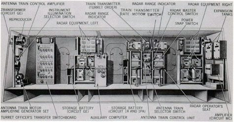
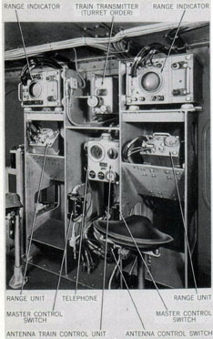
Radar operators
Duties. Two radar operators, one stationed at the left radar set and one stationed at the right radar set, shown in figures 70 and 71, have identical duties. In turret automatic and indicating control, both are at stand-by duty.
Figure 71. Radar Operator's Stations
Ordinarily this means that both operators are tracking the target, ready to assume control of turret train and to provide target range and bearing if the turret is shifted to local control.
In local control, the controlling radar operator uses the train transmitter (turret order) mounted between the radar sets .to train the turret in order to maintain the antenna on the target. He manipulates three hand cranks: one for introducing turret train angle, which is transmitted to the gun train indicator and to the train receiver-regulator; another for determining radar range of the target; and a third for radar antenna train. The last is used only when initially training to the target bearing.
In local turret control, either the left or the right radar operator assumes control of turret train. The choice is determined by the target position, the radar antenna being selected which is not affected by gun position or by interference with the ship's structure.
The radar operator verbally relays the target range and bearing via the range talker to the computer operator at the auxiliary computer, so that sight angle and deflection information, in turn, may be relayed to the sight setter.
While tracking the target with the antenna (by the antenna train control unit), the radar operator also trains the turret (by the turret train transmitter at his station), to bring the guns to the same bearing as the beam of the radar antenna. In the meantime, the sight setter cranks in sight angle to correspond with sight angle data received from the auxiliary computer, and at the same time he sets the deflection dials at zero deflection.
When turret train and antenna train are matched, and the sight setter's deflection dials are at zero, control of antenna train (with respect to turret bearing) is shifted to the sight setter, who offsets the antenna in deflection to correspond to the value of deflection derived from the auxiliary computer.
As the antenna revolves to its offset position, the radar operator trains the turret so as to hold the target in the antenna beam. Thus, the guns are trained to the correct angle of deflection. Thereafter, while the turret tracks the same target, the radar operator continuously operates the range unit crank and the turret train order transmitter crank.
80
Equipment used. The equipment used by the radar operators includes the two radar scope installations, the train transmitter (turret order), the antenna train drive control unit, and the radar range unit, all shown in figure 71.
Electrician (turret officer's booth)
Duties. The electrician in the turret officer's booth is the general utility trouble-shooter for turret electrical equipment. He is primarily concerned with maintaining performance of turret electrical equipment in the turret officer's booth and the gun room, except fire control and radar gear. He acts as a roving trouble-shooter during turret operation, making circuit continuity checks, replacing fuses and indicator lamps, and otherwise repairing and replacing electrical elements in any instance of malfunction or failure of gun controls, transmission circuits, communications, battle illumination, and the ready light system. In battle, his foremost duty is as an additional aide for the gun captains.
Equipment used. In performance of his duties, the electrician employs the tools and accessories of the electrical test and service maintenance outfits. His roving battle station includes servicing of all electrical installations of the gun house and gun pits. This includes the electrical equipment of the guns, the elevating gear drives, the hoists, all receiving, transmitting, and indicating units of the booth, and the sight stations, except fire control and radar equipment.
Gun captains
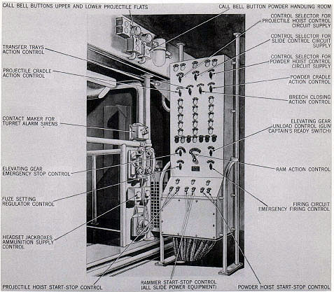
Duties. Each of the three gun captains is directly responsible for master control and supervision of a gun. He manipulates the power supply and master switching controls which govern operation of the ammunition hoists, fuze setter, and his gun. He directs the activities of the gun captain's assistants in correcting malfunctions of the gun. As ammunition supply talker, he directs powder and projectile handling room service to the hoists. He participates in and supervises all service maintenance, preparation for fire, and securing of his gun at "Cease fire." He has emergency stop and unload control of gun laying, for his gun, as well as emergency firing control.
In preparing for action, he starts the power drives for the slide equipment and hoists of his gun, and closes their respective control circuits. He directs the gun captain's assistant in stowing the slide securing devices, in setting the hoist control selectors, in releasing the gun locking device, in initial opening of the breech, and in appropriately setting the by-pass and accumulator valves of the slide and the air supply valve of the gas ejector. He directs the ammunition supply crews to fill his hoists when so ordered by the turret officer. He personally verifies the charges of the counterrecoil and recoil mechanisms.
During gun firing operation, he observes the continuity of automatic gun loading-firing actions, and is constantly ready to stop the actions of gun and hoists and of gun laying in the event of any malfunction or at occurrence of "Cease fire" order.
After all firing operations, he works with the gun house and hoist crews to unload the gun and hoists; to clean, preserve and stow all gun and hoist units.
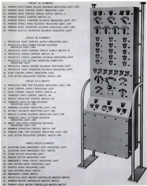
Equipment used. Each gun captain uses telephones and the control panel for his gun. Equipment of a typical station is shown in figure 72. All the switches and indicating lights essential to the duties described above are identified in this illustration.
Gun captain's assistants
Duties. The two gun captain's assistants are stand-by aides to correct the malfunctioning of any gun. They assist during preparation for fire and when securing the guns. Each is responsible to the gun captains and the turret officer for the performance of his assigned duties within the gun room.
In preparing for action, he casts loose the slide securing devices, releases the gun locking device, sets the hoist functional control selectors, releases the turret centering pins, and positions the fuze setter retractor lever latch. During the initial stages of first-round operation, he manually trips the breech bolt to open the breech, and appropriately sets the by-pass and accumulator valves of the slide and the air supply valve of the gas ejector.
During firing, he stands by to assist the gun captain and turret officer as they direct. He is
81
Figure 72. Gun Captain's Control Station. General Arrangement
prepared for any emergency within the gun room, and holds himself ready to go out on the gun girder or within the gun pits to take remedial measures in event of a casualty to the equipment.
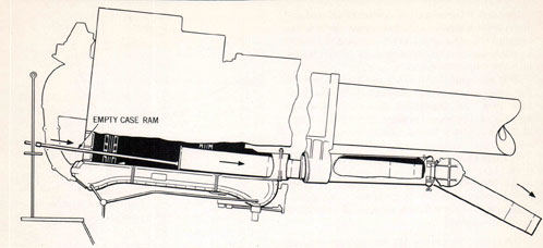
In emergency, during gun casualty operation, he performs or assists in manual case extraction, manual ejection, and the operations necessary to resume normal fire.
At "Cease fire" he assists in the unloading of gun and hoists and the cleaning of equipment, as well as checking, lubricating, and preserving the guns. He assists in ammunition stowage, when the gun hoists are being used to lower ammunition to the projectile flats.
Equipment used. Each gun captain's assistant performs various starting, unloading, and misfire correcting operations on the guns and their related equipment within the gun room. In securing after firing, he uses the standard and special tools and equipment necessary.
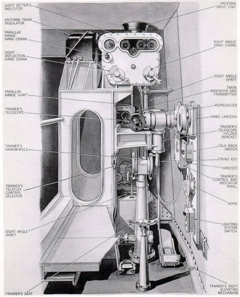
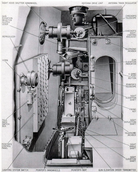
Trainer
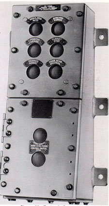
Duties. The trainer is directly responsible to the turret officer for the supervision of operation and control of the training gear. He manipulates the power supply and master switching controls, shown in figure 73, which govern selection of control of turret train.
In starting operations, the trainer positions
82
Figure 73. Trainer's and Sight Setter's Stations
General Arrangement. Rear View
83
Figure 74. Trainer,s and Sight Setter's Stations
General Arrangement. Right Side View
84
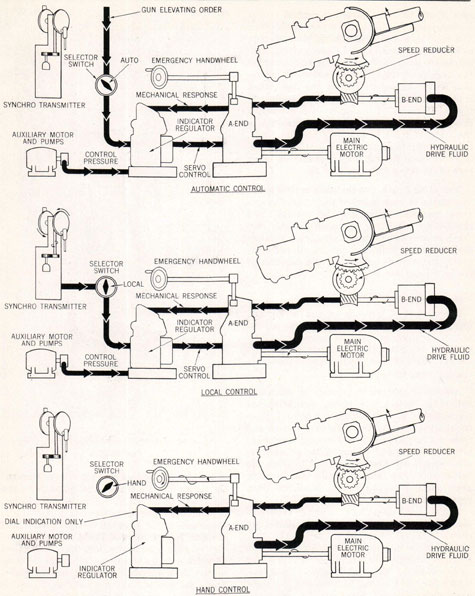
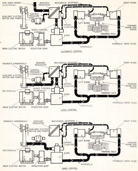
the control selector to HAND and manipulates the switches which energize the training gear power and control circuits. After starting the drive, he positions the selector in LOCAL and brings the turret in correspondence with the indicated train signal, after which, when directed by the turret officer, he positions the selector in AUTO.
In turret automatic control the trainer is at stand-by. He makes frequent target sight checks and watches the dial pointers before him to check that gun position agrees with turret train order. He maintains himself at all times in readiness to assume local control of turret train.
In the event of malfunction of the automatic system, or in response to order to shift to turret indicating control, the trainer positions his control selector at LOCAL and begins follow-the pointer operation. In this instance, gun train order indicated on the gun train indicator is matched by the rotation of the handwheels, so that the trainer is directly training the turret.
In the alternative method of turret local control, with the radar operators using the train transmitter (turret order) to send an electrical turret train order signal directly to the train receiver-regulator, the trainer is again at standby, with his control selector at automatic. The same electrical signal is sent to the gun train indicator. This enables the trainer to shift into indicating control, following-the-pointer, if directed by the turret officer.
In the event of radar failure necessitating a shift to turret local sight control, the trainer rotates his handwheels to maintain his telescope on the target, thus training the turret. In this method of control, he operates his firing key to control gun fire when directed by the turret officer, closing his key when his sight cross lines are on the target.
Equipment used. The trainer's station and equipment are shown in figures 73 and 74. Principal items are the trainer's control and indicator panel, the gun train indicator, the trainer's handwheels, the trainer's ready switch, the firing key, and the sight.
Sight setter
The sight setter is responsible for manually entering mechanical values that offset the lines
of sight and correct gun orders. He performs this duty in all methods of turret control. His station and equipment are shown in figures 73 and 74. He operates the hand cranks of his indicator in response to electrically received dial-actuated orders, or, in local control, according to data received by telephone. These values are for offset depression of the lines of sight from parallelism with the guns, called sight angle; azimuth offset of the lines of sight, called sight deflection; and turret train offset for difference in target angle at the director and the guns, called parallax range. In performing these follow-the-pointer duties, he is entering corrections to the gun orders and moving the pointer and trainer lines of sight. When in local control, this movement compels those operators to rotate their handwheels, and thus move the guns until their telescope cross-lines are on the target.
In all methods of remote control, the parallax range, sight deflection, and sight angle values are electrically transmitted from the plotting room to dials on the sight setter's indicator. Associated dials match up when the sight setter turns the hand cranks and transmits the proper values. He mechanically transmits sight deflection to all the sights. He mechanically transmits sight angle to the elevation indicator-regulators and gun elevation indicator, and, through a sight elevation differential, to the pointer's and checker's sights. He mechanically transmits parallax range to the train receiver-regulator and the gun train indicator.
In local control, when plot orders are not available, values for sight deflection and sight angle are telephoned to the sight setter from the auxiliary computer operator. Under this method of control, the sight setter does not match dials on his indicator, since he has no electrical input to activate the order dials, but cranks in the inputs as received.
In local control, the sight setter's indicator also functions to control deflection of the radar antenna. A signal is transmitted electrically to the antenna train drive in order that the antenna may be offset the same amount as the line-of-sight. The sight setter rotates an antenna control switch on the indicator in order to
perform this operation.
85
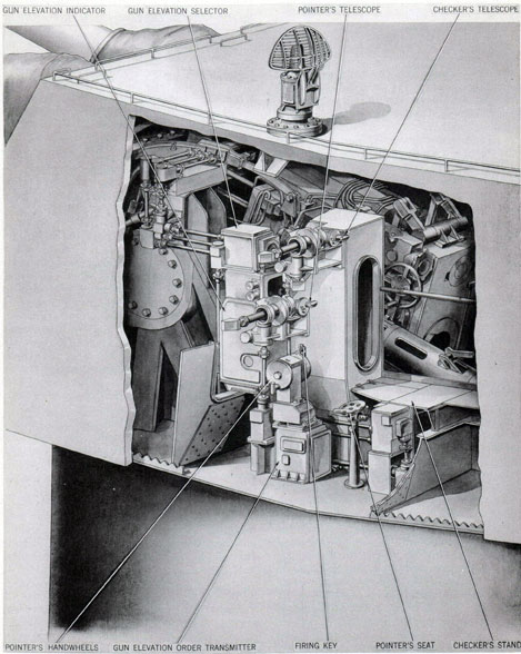
Figure 75. Pointer's and Checker's Stations
General Arrangement. Rear View
86
Equipment used. With exception of the telephones, all of the equipment used by the sight setter is shown in figures 73 and 74.
Pointer
Duties. The pointer is directly responsible to the turret officer for the supervision of operation and control of the elevating gear. He manipulates the power supply and master switching controls, shown in figure 75, which govern selection of control of gun elevation.
In starting operations, the pointer positions the regulator selector switches in HAND and closes the start switches which energize all elevating gear motors.
The three emergency gun layers must man the emergency stations during starting operations in order to position the hydraulic pump (A-end) tilting plates in neutral, which will be indicated by lights on the pointer's panel. When the power drives have been started, the emergency gun layers and the pointer should position the three guns and the pointer's transmitter at approximately zero elevation, at which time the pointer should turn the selector switches to LOCAL. With the guns in local control, the pointer should bring the guns into correspondence with the elevation order shown on the pointer's indicator, after which he may position the selector switches in AUTO.
In turret automatic control, the pointer is at stand-by. He makes frequent target sight checks and watches the dial pointers before him to check that gun position agrees with gun order. He maintains himself in readiness at all times to assume local control.
In the event of malfunction of the automatic system, requiring a shift to turret indicating control, the pointer positions his transmitter to correspond to the elevation order shown on the gun elevation indicator and positions the regulator selector switches at LOCAL and begins follow-the-pointer operation. In this instance, gun elevation order indicated on the gun elevation indicator is matched by the rotation of the handwheels, so that the pointer is directly elevating the guns to the proper angle.
In turret local control, the pointer positions the guns in elevation by sighting through his telescope and maintaining the telescope cross-wires on the target by rotating the handwheels.
In turret hand control, used only in extreme emergency, the emergency gun layers in the gun pits control gun elevation. In this method of control, and when operating under local target sighting control, the pointer, or the trainer, controls gun firing. He has at his disposal a firing key that may be used to fire the guns when the emergency firing circuit has been closed, and he is notified that the turret officer has selected his firing circuit as the one to be used.
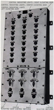
Equipment used. Figures 75 and 76 show the arrangement and identify all equipment used by the pointer. The principal element is the control panel at his left. In this cabinet are ready light indicators for the guns and elevating drives and manually operated switches controlling starting and stopping of each drive, selection of the method of control, and cut-out of the ready light circuits for the individual guns. Immediately in front of the pointer's seat are his hand-wheel controls in a pedestal on top of an electric gun order transmitter; the right hand grip is a conventional firing key. Above the handwheels is his sight telescope, and before this instrument are two indicator dial panels, both visible in the space under the checker's sight bracket. These are the dials of the gun elevation indicator and the gun elevation response selector. The latter instrument is the unit through which one of the gun elevating movements is chosen to provide gun elevation response data for the sights and the gun elevation order correcting devices. It indicates the elevation synchronism of the three guns. The selection is made manually by shifting a clutch lever mounted as shown in figure 75.
At the pointer's right foot is a foot-operated switch through which he signals to the gun captains, the turret officer, the turret captain, and the trainer, when operating in local control, that he is on the target. (Pointer's ready switch).
Checker
Duties. The checker is a gunnery training member of the crew, generally the turret officer, turret captain or an assignment from the gunnery officer's staff. His station is manned only during drill operations or practice firing. It is his duty to coach the turret control personnel
87
Figure 76. Pointer's and Checker's Stations
General Arrangement. Left Side View
88
Figure 77. Projectile Ring and Control Stations
when operating in target sighting local control. Primarily, he is concerned with developing the skill of the pointer and trainer in operating their handwheels to hold the sight cross-wires on the target. But he is also a fire control safety-man who verifies the drill target to prevent firing accident. He cautions the pointer and orders suspension of firing when the turret approaches a position that may endanger the target towing ship or other craft as a result of dispersion, ricochet, straddle, delayed fuze action or other eventuality.
Equipment used. The checker's equipment consists of the sight telescope arranged as shown in figures 75 and 76 and the telephone handset or headset.
Projectile ring operators
Duties. Each of the four projectile ring operators of the turret crew is a controlman
for ammunition delivery to the parbuckler men. Each man separately controls the operation of a projectile ring by manually rotating an inner or outer ring control handwheel arranged as shown in figure 77. These control stations and the responsibilities of the operators differ, depending on the type of ammunition service employed.
Inner ring operators are responsible for maintaining projectile supply for one hoist only. They have visual observation of parbuckling, and thus can see when it is safe to move the projectile ring and when more supply is needed. Each operator's work consists of unlatching his handwheel and rotating it to initiate a ring cycle. He releases the wheel, and the cycle is completed automatically. This action places six projectiles within reach of the parbuckler. It must be repeated when the sixth projectile has been removed from the ring and is being transferred to the hoist.
89
Figure 78. Projectile Man and Parbuckling Man Stations
90
Outer ring operators may have to perform their duties in either of two methods of ammunition service. In one method, the right and left projectile hoists are served from one ring. In the other method, the outer ring of one flat serves the other hoist. The method serving two hoists from one ring requires the operator to be alert to prevent casualty: In this method, the operator cannot observe parbuckling at both hoists; he must watch two indicator dials of projectile ring control circuit RP, unlatching his handwheel and initiating a cycle in the same manner as the inner ring operator when both indicator lights are out.
In addition to their control handwheel duties, all operators are responsible for starting and stopping their respective power drives, and for casting loose and securing the ring centering pins. Between cycles of ring movement, they assist the parbuckling and hoist operators, breaking projectile lashings and steadying projectile transfer.
Equipment used. Accessible to each operator when at his station, are his control handwheel, power drive master push button, and a turret alarm contact maker, circuit RA. In addition, the outer ring operation has a circuit RP indicator. All stations are close to the telephone and public address system units of the flat. All equipment is arranged as shown in figure 77.
Projectile men
Duties. There are three projectile men on each projectile flat, one each located at the right, center, and left steady arm mechanisms of the parbuckling gear. Each projectile man, together with his parbuckler, is a hoist loading operator for parbuckling projectiles from the projectile ring into the hoist. His operations involve grabbing a projectile from the ring with the steady arm device and transferring it into the hoist. This action operates hoist conveyor, door, and trigger controls that cause the power drive of the hoist to lift the projectile one stage or flight cycle.
Equipment used. Each projectile man has the steady arm mechanism and hoist loading aperture controls shown in figure 78. His station includes an emergency stop control switch that enables him to stop the hoist power drive.
Parbucklers
Duties. There are three parbucklers on each projectile flat, one each located at the right, center, and left gypsy heads. Together with the projectile man with whom he teams, each par-buckler is responsible for continuous delivery of projectiles from the projectile ring into the hoist at which he is stationed. His parbuckling work consists of applying snubbing rope tension immediately after the projectile man has grabbed a projectile. This applies power to the steady arm to pull the arm and projectile to the hoist under guidance of the projectile man. He holds snubbing rope tension until the projectile has been ejected from the steady arm.
Right and left parbucklers have additional duties. Every sixth round they must release the spring detent of the circuit RP contact makers. This action extinguishes the light in the indicator at the projectile ring operator's station. It is the signal to rotate the ring one cycle to supply six more projectiles.
Equipment used. A snubbing rope and gypsy head are used by the parbucklers at their respective stations. Typical arrangements are shown in figure 78.
Electrician (lower projectile flat)
Duties. The electrician in the lower projectile flat performs a number of miscellaneous duties. He is primarily concerned with the turret electric supply panels and other electrical equipment located about the flat. During operation, he acts as a roving trouble-shooter, making circuit continuity checks, replacing fuses and indicator lamps, and otherwise repairing and replacing electrical elements in any instance of malfunction or failure.
Equipment used. In performance of the above duties the electrician employs the tools and accessories of the electrical test and service maintenance outfits. His roving battle station includes the servicing of all electrical installations in the upper and lower projectile flats and the powder handling room.
Petty officer in charge (powder handling room)
Duties. The powder handling room petty officer is supervisor of safe powder transfer
91
Figure 79. Powder Handling Room Control Stations
operations. Under the turret officer, he organizes the powder crew, training the men to be skillful in manipulating the powder trucks when serving the powder hoist scuttle. He directs their movements to prevent traffic confusion, orienting the three hoist crews so that they move between the rotating platform and the magazine scuttles without interference. If the service to any hoist lags, he assists that crew.
The importance of these duties is best appreciated by study of the powder service period of the gun operation cycle illustrated in figure 63, and of the crossing routes of the powdermen; see figure 68. If the powder transfer operation from magazine scuttle to hoist conveyor requires more than five seconds, gun operation is seriously delayed.
In addition to the above primary duties, the petty officer has important safety functions.
He and his crew must be alert to prevent transfer of loose powder; an unsafely crimped plug of a powder case will spill powder in the gun loading action; a damaged case or primer will cause misfire or other stoppage.
If a powder case spills in the powder room transfer operation, he must be ready to get rid of the debris so that hoist service will not be delayed.
If any fire hazard is indicated or occurs, he must operate one or both of his sprinkling controls.
When starting up operations, it is his duty to ascertain by careful inspection and operating tests that all magazine and hoist scuttles are safe and in perfect operating condition.
Equipment used. The equipment used by the petty officer consists of the communications units mounted on the central column panel as
92
shown in figure 79, the controls of sprinkling station C, and a short length of fire hose connected for battle operations at the globe valve hose connection of the fire main water supply line, shown in figure 79. In addition, as supervisor, he is directly responsible for the condition of all scuttles, the six powder trucks, the floor, and all hoist communications, and the secured condition of the ordnance stores rooms behind the hoists.
Powdermen
The three groups of powdermen identified in figure 64 have identical operations in supplying their respective hoists.
Duties. The first and second powdermen are engaged exclusively in powder transfer. Their operations require skill in removing powder cases from the magazine scuttles and in loading the hoist scuttle. The latter action must be performed smartly to carry the case through the doors and actuate the trigger positively; hasty loading, rolling of ship, and slippery deck can give nonpositive action, possibly cause a "spill," or otherwise delay or stop hoist service.
The powderman currently loading the scuttle chamber of each hoist should, after making sure that the powder case is fully inserted, manually operate the scuttle control switch CQ to the position marked "Chamber A to hoist" or "Chamber B to hoist," and observe operation of the scuttle to insure hoist service. In event of scuttle or hoist jam, he must stop the hoist. He must assist in unblocking the stoppage and in getting his hoist drive back into normal powder delivery. In event of failure of the power drive of his hoist scuttle, he must man the hand crank drive for that unit after loading the case into the shuttle. He must also comply with the gun demands and instructions of the gun captain. The third powderman is stationed on the fixed structure at a convenient position for manually rotating the magazine scuttle by means of the operating handle. His normal duties consist of rotating the magazine scuttle when the visual scuttle signaling device indicates that loading on the magazine side is completed. He must, insofar as practicable, rotate the scuttle so as to avoid interference with the
first or second powderman while powder eases
are being removed from the scuttle, and also avoid blocking passage of other powdermen.
Equipment used. The first and second powder-man's equipment comprises specially designed and easily maneuvered powder trucks, hoist scuttle, scuttle controls, scuttle manual drive, the hoist emergency stop switch, and telephone communication to his captain.
The third powderman's equipment comprises the magazine scuttle.
PREPARING FOR OPERATION
One hundred and sixty-three manually performed operations* are required to cast loose a secured turret and to start equipment preparatory to firing. This is a minimum preparation schedule that must be performed after stations are manned. Approximately 240 additional manual actions are required to fill the six ammunition hoists. These activities not only require time, but many of them depend on other time-consuming characteristics of the equipment that delay firing until system temperatures and pressures can build up. It is therefore important that the work to be done must be coordinated by dividing duties amongst the crew and establishing a duty-sequence for each man. This organization of the work should consider the design arrangements for access, turret exterior operations, work priority, and locations of controls, all as briefly reviewed in the paragraphs following.
Manning stations
The turret design plan for personnel access is through three doors: the center door in the gun
house rear plate and the two doors in the turret foundation at the powder handling flat. The
right and left doors in the gun house rear plate are not personnel access doors; they were designed for serving ammunition to the turret and for relining the guns. Both should be closed and secured at all other times.
* Thirty-six casting-loose operations, releasing centering pins, tube covers, periscope covers, sight hoods, and securing hatches and doors; 127 starting operations, opening cut-off valves, opening breeches, setting switches, checking air and hydraulic systems, closing power circuits, setting ventilator and sprinkler system controls, and establishing control communications.
93
The crew may be routed through the three doors by any of several alternatives, but the recommended routes are based on a secured center gun pit hatch. This requires all stations below the pan to be manned through the turret foundation doors, while the gun house crew only use the door at the rear of the turret officer's booth. It is a route plan that enables all three guns to be brought into action simultaneously. Any alternative that mans the upper and lower projectile flats through the gun house and the center gun pit delays operation of the center gun. With the condition watch on duty and hoists full, this alternative is therefore inappropriate and unsafe.
Starting operations
Seven classes of manually performed operations are involved in starting turret operations. These are:
Auxiliary service operations: Lighting, ventilating, heating, air supply, and sprinkling control operations
Releasing secured equipment
Securing hatches, doors, hoods, and covers
Establishing communications
Ordnance inspection and test operations
Ordnance equipment preparations
Ordnance starting operations
Auxiliary service operations. All operations applying to the first class of starting activities are within the turret. They are "first" duties for the crew. Location arrangements and logical crew assignments for accomplishing them are as follows:
LIGHTING. Mounted to the right of the center access door, on the left side of the right radar gear, is a 12-circuit distribution box. Switches on the box provide selective control for closing all lighting and portable electrical equipment circuits within the gun room and the turret officer's booth. An additional circuit provides master illumination cutout, within these areas, by door-operated switches at each of the three doors. The turret captain or the roving electrician normally operates switches on this box to obtain the desired lighting conditions, selecting normal lighting (diffusing fixtures), or battle illumination (red globe fixtures), as necessary. The turret officer opens or closes
the door switch master cutout switch, at his station, as necessary.
An 8-circuit distribution box is mounted on the partial bulkhead at the turret captain's station. Switches on the box provide selective control of lighting and receptacle circuits within the gun pits and at various other points about the pan plate. The turret captain normally operates these switches to match the lighting conditions in the gun room and turret officer's booth.
An 8-circuit distribution box is mounted on the inside of the inner circular bulkhead, to the rear, within the upper projectile flat. Switches on the box provide selective control of magazine-type lighting fixtures and receptacle circuits within the upper projectile flat. Normally, these switches are operated by the inner ring operator.
An 8-circuit distribution box is mounted on the inside of the inner circular bulkhead, to the rear, within the lower projectile flat. Switches on the box provide selective control of magazine-type lighting fixtures and receptacle circuits, within both the lower projectile flat and the powder-handling room. Normally, these switches are operated by the inner ring operator.
INSTRUMENT ILLUMINATION. A snap switch, located on the right inner end of the turret officer's booth, provides control of illumination of instrument dials and sight crosslines for certain equipment in the gun house. The snap switch has four positions; two OFF positions, TOP BATTERY, and ILLUM. TRANS. Ordinarily, the switch will be positioned at ILLUM. TRANS., which serves to step-down the 110-volt, 60-cycle, ship's service supply to the 6-volt current required by the instrument illumination circuit. When the switch is positioned at TOP BATTERY, an emergency supply for the circuit is available from a 6-volt SBM, 100-ampere-hour storage battery. Rheostats in the circuits to the checker's telescope, pointer's telescope, and trainer's telescope provide dimming control for each of these circuits. The rheostats are located within convenient reach of the users of the respective telescopes, at their stations.
VENTILATION. Two controllers, one for each- of the two ventilating systems, are
94
mounted at the left side of the turret officer's booth. The controller for the system No. 1 ventilating set is equipped with push buttons which provide start, stop, and reset and emergency control. The controller for the system No. 2 ventilating set is equipped with push buttons which provide high and low speed start, high and low speed emergency run, and stop control. Normally, the roving electrician in the turret officer's booth depresses the START push buttons of these controllers to place the ventilating sets in operation. He also operates the mechanisms for manually setting the exhaust and inlet parts in the overhang at their open detent positions. Air exhaust is automatically regulated to maintain the desired pressure within the turret.
AIR SUPPLY, GAS EJECTOR SYSTEM. Ordinarily, the gas ejector air supply will always be open and under pressure. Either the turret officer or the turret captain may observe their respective pressure gages at their stations to check system pressure. However, there are gate valves in the system beyond the take-off for the gage piping, and these must be checked. Valves are plainly marked, such as GAS EJECT. TO RIGHT AND CENTER GUNS CUTOUT, and GAS EJECT. CUTOUT, and are located within the gun pits, and in the gun room. They usually are checked by the gun captain's assistants when so directed by the turret officer. Should system pressure not be indicated at the gages, it is necessary to check and open the valves at the low-pressure separator in the upper projectile flat, at the gas ejecting relay tanks on the lower projectile flat, and in the piping throughout both projectile levels and the powder-handling room. This is done by designated men on the respective levels, as directed by the turret officer or turret captain.
AIR TO SPRINKLING TANKS. In ordinary turret drill operations, sprinkling tanks are filled with water at all times, but are not under air pressure. In preparing for battle conditions, air pressure is placed on the water in the tanks. The procedure is as follows. The turret officer directs that the two valves in the air line be opened. One valve, labeled AIR TO SPRINKLING TANKS is located on the high-pressure side of the reducing valve on the pan bevel,
right side; the other valve, labeled AIR TO SPRINKLING TANKS is located in the turret officer's booth, close to the air control cock. With these valves open, the turret officer then sets the air control cock in his booth to VENT position. After water appears at the overflow, the cock is kept at vent position until both sprinkling tanks are free of air. At that time, the air control cock is set to. AIR SUPPLY position. A pressure gage adjacent to the air control cock supplies information as to system pressure.
HEATING. Space heaters, located at six control stations in the turret officer's booth and three control stations in the pan plate, provide heat for turret personnel. Two four-circuit distribution boxes are located one above the other on the gun-room side of the partial bulkhead at the rear of the left gun, and one six-circuit distribution box is located on the gun-room side of the partial bulkhead at the rear of the right gun. An ON-OFF snap switch at each box controls the power supply of all heaters fed by the boxes. These are switched on by the gun captain's assistants, when directed. The heaters are located at the radar operator's station; left, center, and right gun captain's station; pointer's station, and trainer's station; and a heater is located at each of the three elevating gear emergency control stations in the forward half of the gun pits. Each heater is provided with an adjacently mounted ON-OFF snap switch, which is operated by personnel at the heating stations to provide heat as desired.
Casting loose
Casting loose operations consist of opening covers, such as the sight hood shutters, periscope hood covers, case ejector tube covers, and muzzle covers; and of releasing the various securing devices on the gun, slide, turret, and projectile rings. These are individually covered in the following.
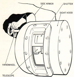
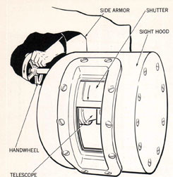
Opening sight hood shutters. The pointer, trainer, and checker are each provided with a telescope. Telescope sight ports in the side armor are each fitted with a sight hood, shutter frame, shutter rack, shutter, and handwheel pinion shaft operating mechanism. The arc-shaped shutter rotates in the frame under
95
Figure 80. Opening a Sight Hood Shutter
handwheel movement, approximately 2 3/4 turns of the handwheel being required to open the shutter. The pointer, trainer, and checker each turns the shutter handwheel at his respective station to open the sight hood shutter, as shown in figure 80. Handwheels are located just inside the side armor, at the sight ports.
Periscope hood covers. Personnel designated by the turret officer open the periscope hood covers, reached from the exterior top of the gun house. The covers are secured by a wing nut which must be removed; the cover is then swung to the open position and secured open by another wing nut.
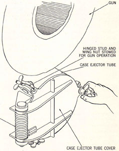
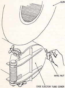
Case ejector tube covers. The spring-loaded case ejector tube covers are each secured by three hinged studs fitted with wing nuts. Personnel designated by the turret officer loosen the wing nuts and hinge and secure the studs to one side, as shown in figure 81, so that the tube covers may be sprung open by the ejecting action of the empty cases. Spring action closes the covers, but does not secure them, immediately after an empty case is ejected.
Tompions, muzzle covers. Personnel designated by the turret officer remove the tompions or muzzle covers. Removing a tompion requires
that the tompion clamping bolt be loosened with a proper wrench and the tompion then lifted out.
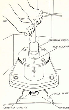
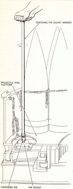
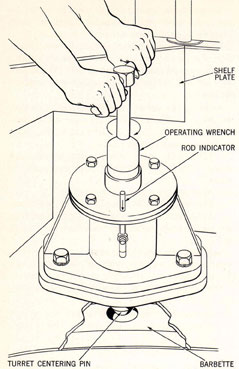
Releasing turret centering pins. Two turret centering pins are provided, one in each rear corner recess of the shelf plate, at the rear of the gun room. An operating wrench for each pin is mounted on the bulkhead adjacent to the pin. The gun captain's assistants normally release the pins, as illustrated in figure 82. The wrench is used to turn the screw bolt head of the centering pin, a clockwise turning movement screwing the bolt into and raising the centering pin from the tapered centering hole in the barbette in which it fits. The clockwise turning direction to clear the pin is shown on the name plate secured to the top of the flanged mounting in which the pin rides. At the side of this flanged mounting is a rod indicator assembly, which is attached to and rides with the pin. An arrow is marked on the side of this rod. When the centering pin has been raised clear of the barbette, the rod indicator will have risen
Figure 81. Securing Case Ejector Tube Cover for
Action
96
Figure 82. Releasing Turret Centering Pin
up through the flanged mounting, so that the point of the arrow is flush with the top of the flange. Travel distance of the pin is approximately two inches.
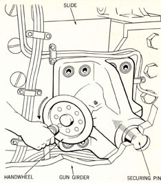
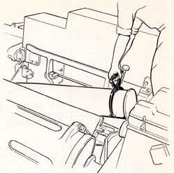
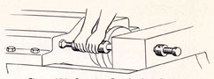
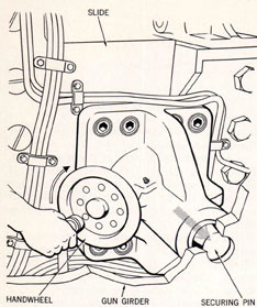
Releasing slide steady rests and securing pins. When directed by the turret officer, the gun captains or their assistants release the slide steady rest and securing pins, as shown in figure 83. These are similar hand-operated screw-type mechanisms mounted on opposite sides of each slide. The securing device is on the inboard side of the slide and should be released before the steady rest, which is on the outboard side of the slide. By turning the respective handwheels, the securing-device pin is withdrawn from its bore in the gun girder
and the steady rest from its position against the gun girder.
Figure 83. Releasing Slide Securing Device
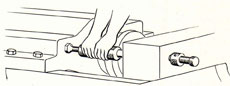
Figure 84. Releasing Gun Locking Device
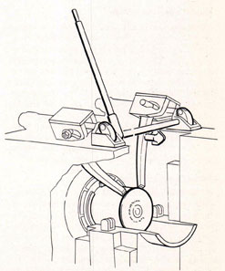
Releasing gun locking device. Each gun is provided with a gun locking device which secures the gun and housing assembly to the recoil cylinder. When directed, each gun captain, or one of the gun captain's assistants, disengages the locking device on his gun by loosening the locknut and turning the connecting screw until it is unscrewed from its safety link, and then tightening the locknut until the mechanism is secured in the stowed position. The method is shown in figure 84.
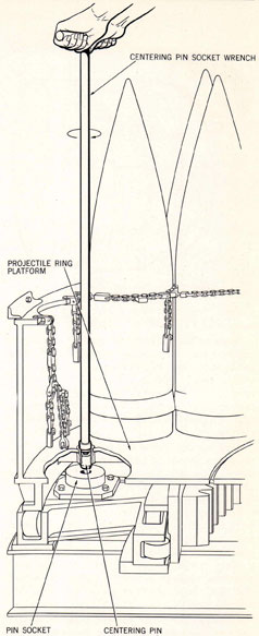
Releasing projectile-ring pins. Each projectile ring has two retractable screw-type centering pins, which fit in mating sockets bolted in position in the assemblage of fixed roller cages. A special socket wrench is stowed in a clip at each pin station. The ring operator, or a designated projectile man or parbuckler, retracts the
97
Figure 85. Releasing Projectile Ring Centering Pin
ring pins using the special wrench, as shown in figure 85, until the white CLEAR indicator is visible in the top of the pin.
Establishing communications
Simultaneously with the preceding starting activities and during performance of certain of the ordnance equipment control setting operations described below, it is imperative that communications be established throughout the turret. This is particularly necessary when closing the supply circuits and manipulating the controls of the electric control systems of the guns, the ammunition hoists, and the gun laying drives. None of the automatic mechanisms should be placed in operation until control members of the crew have received reports that the casting-loose operations and inspections have been completed and that the gun pits, the slides, the projectile rings, and other hazardous areas are clear of personnel, tools, accessories, and supplies; "ready" reports should be coordinated by clearing them through the turret captain.
Communications employed in this essential phase of the starting operations, and subsequently, are the public address and telephone systems. A minimum of 18 members of the crew must install telephone headset receivers and talk-back microphones; others may be similarly equipped according to the turret officer's plan of organization. The required wearers are: the turret officer, turret captain, and computer operator, the three control talkers (see figure 64) , the three gun captains, the pointer, trainer, sight setter, and checker, the three emergency gun layers (temporarily manning their stations when starting), and at least one man (usually the petty officer in charge) on each of the projectile and powder handling flats.
ORDNANCE EQUIPMENT PREPARATIONS AND STARTING OPERATIONS
Starting operations, described in the paragraphs following, include safety checks, operating precautions, and operating tests that are performed on all ordnance assemblies; also the turning on of turret primary power and starting drives.
98
Safety checks, operating
precautions, and tests
Personnel must be fully cognizant of the necessary operating precautions and safety checks. All ordnance assemblies require periodic maintenance and inspection. When preparing for operation and before starting any of the electric motors, it is necessary to verify that proper lubrication has been performed; that hydraulic fluid and oil levels, and high and low air pressures, are adequate and available; that the equipment has been cast loose; and that all personnel are clear. These and many other detailed precautions, tests, and checks are noted in other chapters. They should be performed prior to operation. Checks are performed by the personnel directly controlling the various assemblies, or, if inconvenient, by personnel designated by the turret officer.
Energizing main power circuit
A manual bus transfer panel at the rear of the upper projectile flat, on the inner wall of the inner circular bulkhead, provides two external switches for controlling normal and alternate power for major electrical installations in the turret. Power from the bus transfer panel is transferred to five adjacent circuit breaker power panels; these are the three gun equipment power panels, a training gear equipment panel, and a miscellaneous equipment power panel. Each power panel is provided with an external handle which permits manual cut-off of power. The electrician (projectile flat) turns the chosen bus transfer panel switch to the ON position. If normal power is used, an indicator light above the switch indicates NORMAL POWER AVAILABLE. If alternate power is used, an indicator light above the switch indicates ALTERNATE POWER AVAILABLE. Both of these switches also function to light one of two dial lights on the remote power available indicator in the turret officer's booth, lighting NORMAL or ALTERNATE, depending on which source of power is being used.
Gun equipment power panels supply power to the projectile hoist, powder hoist, slide-rammer, and elevating gear assemblies of their respective guns. The training gear equipment panel supplies power to the training gear drive. The miscellaneous equipment power panel supplies
power to the following assemblies: projectile rings, parbuckling gear, ventilating systems (2), heating system, IC-FC panel, and radar control amplifier assembly. Each panel cut-off switch is normally turned to the ON position. A mechanical indicator plate located above the operating handle in a small circular window indicates when power is on or off.
Spaced around the inner wall of the inner circular bulkhead on the lower projectile flat are 15 motor controllers which serve to control starting and stopping of power drive motors for the hoists, slide-rammer assemblies, projectile rings, and parbuckling gear. At the rear of the pan level are mounted three elevating gear controllers and one training gear controller. Each controller is equipped with a main line disconnect circuit breaker or switch which is manually operated by an external lever. Ordinarily, these levers are always left in the ON position. The ON or OFF position is indicated by an ON-OFF-TRIP name plate on the controller cabinet. Electricians on these levels inspect the controllers to ascertain that all circuits are closed.
Starting drives
Procedures detailed in the following paragraphs provide the necessary instructions for starting the drive units for all power-driven ordnance assemblies within the turret.
Starting elevating gears. A master pushbutton switch is located on the pointer's control panel, shown in figure 86, for each gun elevating gear. It consists of two push buttons, one labelled START-EMERG and the other STOP. The starting circuit contains a hand start interlock switch and a neutral start interlock switch which operate to prevent starting the elevating gear motor unless the tilting box of the hydraulic pump A-end is at neutral and the regulator selector switch at HAND. Also connected to the master switch is an amber indicating light on the pointer's control panel, designated ELEVATING GEAR NEUTRAL, which is illuminated only when both the hand start interlock switches are closed.
The pointer positions each register selector switch at HAND and each ready light cut-out switch at IN. At this time the ELEVATING GEAR NEUTRAL light on his control panel should flash on. If not, then one of the A-end
99
Figure 86. Pointer's Control Panel
tilting boxes is tilted and will have to be positioned at neutral by operating the emergency handwheels within the gun pits. For this reason, the emergency stations must be temporarily manned when starting.
Immediately after starting operations, the pointer selects the mechanical input of gun elevation to the indicator and sights, using the gun elevation selector. The selector is mounted on top of the elevation indicator, and has three
dials which indicate the relative positions of the three guns. Each dial is provided with an alignment index, so that gun elevations may be synchronized. To select the gun from which gun elevation input will be taken, the pointer has to have the guns elevated at exactly the same angle, so that the same elevation may be obtained after the shift as before it. A synchro mesh prohibits shifting when guns are not aligned. The selection is made by manipulating a bell crank on the right side of the case which connects the clutch shifting lever to the selector clutch in the gun elevation selector.
After the elevating gear motors are started, the pointer may switch control of the guns from HAND to LOCAL. To do so, he checks that the red ELEVATING GEAR STOP light on his panel is unlighted. If this indicating light is illuminated, one of the gun captains or the turret officer has positioned his elevating gear emergency stop switch to STOP, and it will be necessary to have that switch setting changed. The pointer verifies that the amber SYNCHRO POWER indicating light on his panel is lit, signifying that the synchros in the regulator and in the gun elevation order transmitter are energized. He then rotates his handwheels until handwheel elevation order position, as indicated by the handwheel dial, checks with gun elevation as shown by the gun elevation indicator. When these check, the pointer switches the three regulator switches on his panel to LOCAL.
To switch from LOCAL to AUTO, the pointer rotates his handwheels until gun elevation matches gun elevation order, as shown on the gun elevation indicator. When these match, the pointer switches the three regulator switches to AUTO.
Training gear. A master push-button switch is located on the trainer's control panel shown in figure 87. It consists of two push buttons, one labeled START-EMERG and the other STOP. The starting circuit contains a hand start interlock switch and a neutral start interlock switch, which operate to prevent starting the training gear motor unless the tilting box of the hydraulic pump A-end is at neutral and the regulator selector at HAND. Also connected to the master switch is an amber indicating light on the trainer's control panel designated TRAIN GEAR NEUTRAL, which is illuminated only
100
when both the hand start interlock switch and the neutral start interlock switches are closed.
In order to close the hand start interlock switch the trainer positions the control selector, shown in figure 74, at HAND. At this time the TRAIN GEAR NEUTRAL light on the control panel should flash on. If not, then the A-end tilting box is tilted, and will have to be positioned at neutral by turning the handwheels. Ordinarily, this condition will exist only following power failure which stopped the mechanism during operation. When the neutral light is on, push the START button to start the drive.
After the training gear motor is started, the trainer may shift control of the training gear from HAND to LOCAL by shifting the control selector lever. To do so, he first checks that the turret stop light on his panel is unlighted. Should this indicating light be lit, tile turret officer has positioned his emergency training gear stop switch to STOP, and it will be necessary to have the switch setting changed. The trainer verifies that the amber SYNCHRO POWER indicating light on his panel is lit, signifying that the synchros in the regulator synchro circuits are energized. Control may then be changed merely by moving the control selector lever to LOCAL. To switch from LOCAL to AUTO, the trainer rotates his hand-wheels until turret train matches turret train order, as shown on the gun train indicator. When these match, the trainer may then shift the selector lever to AUTO.
Starting slide power equipment. A master push-button switch for each slide-housing-rammer motor is located on each gun captain's control panel. It is identified on figure 72. It consists of two push buttons, one labelled START-EMERG and the other STOP. The switch is arranged with an amber indicating light which is illuminated during motor operation. To start the motor, the gun captain first ascertains that the slide control circuit supply switch, designated on figure 72, is in the OFF position, after which he momentarily depresses the START-EMERG push button. Control action is started separately as described on page 102.
Starting projectile hoists. A master push button switch for each projectile hoist is located on the gun captain's control panel, as identified
Figure 87. Trainer's Control and
Indicator Panel
on figure 72. It is the same type and arrangement as the slide power equipment starting switch, including an amber indicating light which is illuminated during motor operation. To start the motor, the gun captain momentarily depresses the START-EMERG push button.
This action starts the power drive only. Hoist action cannot commence until the control system is started as described on page 102.
Starting powder hoists. A master push-button switch for each powder hoist is located on the gun captain's control panel as identified on figure 72. It is an arrangement identical to
101
the projectile hoist switch, including an amber indicating light which is illuminated during motor operation. To start the motor, the gun captain momentarily depresses the START-EMERG push button.
Starting projectile rings. A master push button switch for the inner projectile ring motor is mounted on the control panel at the rear of the central column of the respective flat, as shown in figure 77. A master push-button switch for the outer projectile ring motor is mounted on the outside of the circular bulkhead, above and to the left of the archway of the respective flat. All four of these switches are identical, each consisting of two push buttons, one labeled START-EMERG and the other STOP. To start any projectile ring, the ring operator first centers the control handwheel in the locked or neutral position. This is necessary because the starting switch is arranged with a neutral interlock switch which prevents starting when the pump yoke is offset from the neutral position. The operator then momentarily depresses the START-EMERG switch.
Starting parbuckling gears. Each of the upper and lower projectile flat parbuckling gear motors has a master push-button switch located on the control panel at the rear of the central column is identified on figure 77. The switches are identical to those described above for the projectile rings. To start the motor a projectile man or parbuckler momentarily depresses the START-EMERG push button.
Setting controls; energizing the control circuits
Two classes or groups of controls must be set and their electric supply circuits must be closed when starting turret operations. These are the ordnance equipment controls and the turret officer's controls. Both groups of operations are described in the paragraphs following and references.
Ordnance equipment control setting. The automatic gun control systems, the hoist control systems, and the elevating and training gear regulator control (AUTO) devices are not placed in operation by the power drive starting operations described on pages 99 to 102. Gun and hoist systems are started by manipulating
certain gun captain and hoist function selector controls; elevating and train systems by setting certain turret officer controls.
Gun and hoist controls. Each gun control system is placed in operation when the gun captain closes the electric current supply switch designated on figure 72 as "control selector" for slide control circuit supply." Similar supply switches on either side of this switch enable him to energize the projectile and powder hoist control circuits, but those circuits are not placed in operation until the gun captain's assistants go forward on the gun girders and shift function control selector levers, one for each hoist, which are located near the deck lugs and are normally stowed in STOP position. Each lever must be placed in HOIST position to set the conveyor and cradle controls so that the hoist will automatically deliver ammunition units to the slide.
When the hoist and gun control circuits are thus energized, ammunition is delivered to the gun through the manual, mechanical, and hydraulic operating system actions described in "Firing operations, first round," on pages 104-8.
Turret officer controls. All fire control signals and communications transmitted to the gun laying indicators and regulators, the pointer, trainer, and sight setter, and the fuze setting devices are routed through controls set by the turret officer. They are electric switching controls compactly arranged in the large transfer switch panel located as shown in figure 70. The 25 switch units of this panel have slightly different circuit arrangements and switch position identities for turrets I, II, and III. These differences, as explained in Chapter 14, apply only to local arrangements which enable turret II to provide Hi-turret control for turret I. AUTO control arrangements of the three panels are essentially the same as the turret II panel details illustrated in figure 88. This picture and the switch positions tabulated in the list below show the settings for providing remote automatic control (PRIMARY or SECONDARY AUTO) for turret II, as typical.
Switch No.
Switch Position
1
FWD
2
Any FWD position
102
Figure 88. Turret Officer's Transfer Switchboard
Switch No.
Switch Position
3
Any FWD position
4
OFF
Switch No.
Switch Position
5
FWD
6
ON
103
Switch No.
Switch Position
7
FWD
8
FWD
9
TRAIN
10
OFF
11*
12
Any FWD position
13
Any FWD position
14
Any FWD position
15
Any FWD position
16
FWD
17
FWD
18
OFF
19
OFF
20
OFF
21
OFF
22
OFF
23
FWD
24A
FWD
24B
OFF
25
FWD
All switches that may be positioned at either FWD or AFT must be positioned similarly; i.e., all at FWD or all at AFT. There are two groups of indicating light panels on the switchboard, each of which may be energized from the plotting rooms. One set, when lighted, notifies the turret officer that the forward plotting room is in control; the other set that the after plotting room is in control. All switches are positioned according to the directing lights.
Two warning buzzers are provided which will sound when any FWD or AFT switch is incorrectly positioned.
In addition to the above-described switches, the turret officer also operates the turret officer's selective switch, mounted on the upper partial bulkhead at his station. This consists of a pair of rotary switch elements, one labeled DIRECTOR-OFF-LOCAL, the other AC SUPPLY-OFF-BATTERY. By rotating these switches, the turret officer selects local or remote firing, and the source of power to energize the firing circuit.
The turret officer's indicator panel on the partial bulkhead at his station comprises 24 indicator light dials, and three rotary snap
*No. 11 is a spare switch.
switches. The lights show the condition of readiness of the guns and gun laying drives. Of the three switches, the first switch cuts in or out the trainer's firing key; the second switch cuts in or out the pointer's firing key; and the third switch is an emergency firing switch for all guns. Under the conditions outlined above; i.e., in normal automatic fire, with guns under primary or secondary control, the turret officer positions the firing key switches at OUT, and the emergency firing switch at OUT.
A snap switch on the partial bulkhead at the right of the turret officer's station is used to shift from director control to local control of the salvo signal system. Under director control, the turret officer positions this switch at DIRECTOR.
FIRING OPERATIONS
First round
In preparing for the first round, a decision is necessary as to whether projectiles will be loaded from the upper, lower, or both projectile levels. The turret officer directs personnel in the lower projectile level to position the three hoist loading level selector switches, which are mounted near the top of the level adjacent to their respective hoists. If, for example, it is directed that loading be from the upper projectile flat, the switches are each set at UPPER. A mechanical indicator, shown in figure 89, located at each hoist on the lower level, then reads DO NOT LOAD continuously. The arrangement may be reversed, or both levels may be used; the lower level indicators being mechanically interlocked with projectiles in the hoists, so that personnel on the lower level are always aware when a projectile should be loaded.
Each of the projectile hoist and powder hoist functional control selector switches must be properly set as described on pages 102-104.
If H.C. nose-fuzed projectiles are being used, the fuze setter retractor lever latch on the upper end of each of the hoist cradles is moved to the DOWN position by the gun captain's assistants. The latch is placed in the UP position when handling other projectiles.
At this stage, each gun captain takes over control of his respective gun. He positions
104
switches on his control panel as follows:
Switch B-Projectile hoist control supply-NORM.
Switch A-Slide control supply-NORM.
Switch C-Powder hoist control supply-NORM.
Switch BJ-Projectile cradle control-AUTO
Switch AB-Transfer tray control-AUTO
Switch AP-Breech close control-AUTO
Switch CJ-Powder cradle control-AUTO
Depending upon whether or not H.C. projectiles with nose fuzes are being used, the gun captain positions the FUZE SET REG CONTROL switch at OFF, SAFE, or RUN. Instructions on the' positioning of this switch come from the turret officer.
The gun captain directs his assistant to trip the breech bolt manually to open the breech; to check that the manual breech operating mechanism is declutched, and to check that the slide accumulator shut-off valve is open.
Serving hoists. When the preceding preparations are completed, the projectile men and parbucklers on the designated loading level are directed to begin serving the projectile hoists, and the powder men to begin serving the powder hoists.
A projectile man and parbuckler work together to parbuckle projectiles into the hoist aperture. The projectile man operates the steady arm mechanism, as shown in figure 90, to grab a projectile. The parbuckler operates the snubbing rope, looping the free end of the rope twice around the gypsy head and pulling it tight enough to provide snubbing action that brings the projectile end of the steady arm to the hoist loading aperture. The projectile man operates the handwheel on the steady arm mechanism to guide the projectile. As the projectile reaches the hoist opening, forward travel of the steady arm is halted; the rammer is released and ejects the projectile into the hoist. At the moment of complete ejection, hand-pull of the snubbing rope is released, and the steady arm is pivoted away from the hoist, ready to grab another projectile. Inner and outer ring operators operate their respective handwheels every six rounds, to position the projectile rings so that the projectile men may reach the stowed projectiles with the steady arm mechanisms.
Figure 89. Hoist Loading Level Selector
Three powdermen work together to load each powder hoist. Two men operate powder case trucks while the third operates the magazine scuttles. The two truck operators alternately load a powder case from the powder-passing scuttles in the circular foundation into their trucks, roll the loaded trucks onto the rotating powder handling platform, and tilt the cases from the truck into the powder hoist scuttle. The scuttle drive control switch is then moved to rotate the shuttle so that the loaded powder case is placed within the hoist conveyor. Scuttles are designed so that the rotating shuttle has two opposed loading chambers; when one side is enclosed within the hoist, the opposite
105
Figure 90. Projectile Parbuckling Operations
side is exposed for loading. As soon as the enclosed powder case is carried upward, the shuttle is again rotated, when the drive control switch is moved, to deliver the next case to the hoist and expose the opposite side for loading. The truck operators arrange their traffic
so that, as one is loading his powder case truck from the magazine scuttle, the other is tilting a powder case into the hoist scuttle. Each should complete his operation at the same time and trucks should pass each other en route from one scuttle to the other.
106
Figure 91. Projectile Transfer Tray Firing Position
Filling hoists. As a projectile is parbuckled into the projectile hoist, and a powder case enclosed within the powder hoist, these ammunition units depress pawls in the loading apertures of their respective hoists. The pawls operate to close electrical interlock switches in their respective hoist control circuits. Since all other interlock switches are closed in the hoisting circuit, the action of the pawl in closing the switch completes the hoisting circuit. Hoist drives thereupon operate to move the ammunition units one flight upward, at which time the circuits are broken and hoisting ceases until the next units are loaded. As successive ammunition units are loaded, the drives continue to operate until the first ammunition units loaded enter their respective hoist cradles. The cradles then rise automatically and latch to the slide.
Fuze setting. Fuze setting of H.C. nose-fuzed projectiles is accomplished while the projectile is within the projectile hoist cradle. Operation of the mechanism in the cradle is controlled by a switch on the gun captain's control panel.
The switch may be positioned at OFF, SAFE, or RUN. Should it be placed at RUN, a fuze setting signal from the plotting room is relayed through the turret officer's transfer switchboard and the control panel to the mechanism. Should the switch be placed at SAFE, a dummy signal is relayed to the mechanism which operates to fix the fuze at the standard safe position. For non-fuzed projectiles, the switch is set at OFF.
Ammunition transfer. With the breech open, transfer trays extended to the firing position, hoist cradles latched to the slide, empty-case tray empty, and the fuze setting circuit either OFF or CLOSED, conditions are readied so that both the projectile and the powder case are spring-ejected into their respective transfer trays, as shown in figures 91 and 92.
Loading. The gun captain then positions the transfer tray control switch, figure 72 (designated also by symbol AB), from AUTO to RAM; the transfer trays move over to the ramming position shown in figure 93.
107
Figure 92. Powder Transfer Tray Firing Position
Simultaneously, both cradles unlatch and lower to the hoists. Switch AB is then positioned at AUTO.
Ramming. In order to start the ramming action, the gun captain moves the rammer control, figure 72 (designated also by symbol AM), from RETRACT to RAM, and the ammunition units are rammed into the gun. He releases the lever, and the action is automatically completed. As the rammer retracts, the breech closes. Upon the completion of retraction, the transfer trays move back to the firing position. During the ram stroke, the cradles are latched to the hoists and are automatically loaded with the next round.
Firing. When the breech closes, the firing circuit is completed and the gun is fired electrically by remote control. During recoil and counter-recoil, the breech bolt is tripped automatically and the breech is opened. During firing and breech opening actions, the cradles move from the hoists to the slide. Both cradles are latched
to the slide by the time the breech is open. Immediately following breech opening, the empty case is extracted from the breech. Extraction of the case and its delivery to the empty-case tray close a switch that completes the circuit which governs the movement of the transfer trays from firing to ramming position. For the initial round, since an empty case is not present, transfer-tray movement to ramming is controlled by the gun captain, who manually positions switch AB to RAM.
Case ejection. The empty case is deposited in the empty-case chute when the transfer trays reach the ramming position. Presence of the case in the chute closes a switch which starts the empty-case drive unit, and the empty case is thrust forward into the closed section of the chute.
Normal automatic fire
Thereafter switch AM, rammer control, is held in the RAM position continuously. Since the transfer trays are in the ramming position
108
(see figure 93) , the ramming control circuit is closed and the ramming action takes place. The cycle then continues automatically, as long as switch AM is held in the RAM position, with successive and simultaneous operations closing the various circuits. Normal automatic operation begins immediately after the first round is fired. The breech is opened automatically during counterrecoil. The empty case extraction closes the switch and the circuit that moves the transfer trays to ramming position. Thus, the two operations that, on initial loading, required manual control, are automatically taken care of following first-round firing .
Indicating lights, gun captain's control panel. The status of each phase of the cycle of operations discussed above may be observed and checked by indicating lights on the gun captain's control panel. These lights, appropriately designated, light up as their circuits are energized, and remain lighted for the duration of the individual operation.
Gun laying, firing
Turret control methods of gun laying and firing include primary or secondary AUTOMATIC control, primary or secondary INDICATING control, LOCAL control and HAND control. Each of these methods is described in the following text.
Automatic control. In primary or secondary automatic control, gun laying and firing are accomplished entirely by remote control. Electrical signals to lay the guns in elevation and train the turret are relayed from either forward primary, forward secondary, after primary, or after secondary director and plot through the turret officer's switchboard to the gun elevating gear indicator-regulators and the turret train receiver-regulator.
Inputs to the elevating gear and to the training gear in the various methods of control are shown in figures 94 and 95, pages 110-111.
Sight deflection and sight angle orders are relayed through the turret officer's transfer switchboard to the sight setter's indicator, where the sight setter, in matching the sight angle order by hand, transmits this order mechanically to the gun elevation indicator and the three gun elevation indicator-regulators, as well
Figure 93. Projectile and Powder Transfer Trays
Ram Position
as the sights. Parallax range is relayed through the turret officer's transfer switchboard to the sight setter's indicator, where the sight setter, in matching the order by hand, transmits it mechanically to the train receiver-regulator and the gun train indicator. These inputs are factors of gun order correction. Sight deflection, although not used in automatic control, is transmitted to the sights for checking purposes. These factors are automatically combined in the regulators and other instruments to correct the range position of the guns and the azimuth position of the turret.
109
Figure 94. Elevating Gears and Controls
Functional Diagrams
110
Figure 95. Training Gears and Controls
Functional Diagrams
111
During normal automatic fire, turret personnel must at all times be in readiness to switch to any other method of control. The pointer, trainer, and turret officer must be ready to position the various switches at their stations to their new positions. The radar operators and the computer operator must be ready to furnish the values necessary for local control of gun laying.
Indicating control. A second type of control is primary or secondary indicating control. Under this method, gun orders are relayed from the remote control center plot through the turret officer's transfer switchboard to the pointer's and trainer's indicators. Those men operate their handwheels to follow-the-pointer to place the proper inputs into the elevating gear indicator-regulators and the train receiver-regulator. In switching over from automatic control to indicating control, operations are performed by the turret officer, pointer, trainer, and sight setter as follows:
Turret officer. The turret officer positions the switches on his transfer switchboard as follows:
Switch No.
Switch Position
1
FWD or AFT
2
Any FWD or AFT position
3
OFF
4
OFF
5
FWD or AFT
6
ON
7
FWD or AFT
8
FWD or AFT
9
TRAIN
10
OFF
11*
12
Any FWD or AFT position
13
LOCAL**
14
LOCAL**
15
LOCAL**
16
FWD or AFT
17
FWD or AFT
18
OFF
19
OFF
20
OFF
*No. 11 is a spare switch
**This switch selection duplicates the pointer's selector switch. It is a control routing installed at date of this publication, but which will probably be eliminated.
Switch No.
Switch Position
21
OFF
22
OFF
23
FWD or AFT
24A
FWD or AFT
24B
OFF
25
FWD or AFT
All other switches controlled by the turret officer are in exactly the same position as they were in automatic control.
Pointer. The pointer checks that handwheel elevation order position agrees with gun elevation as shown by the gun elevation indicator. When these agree, he switches the three regulator switches on his panel to LOCAL. Thereafter, by rotating his handwheel to follow-the-pointer of the gun elevation indicator, he is actually controlling gun elevation of all guns, via the local gun elevation order transmitter.
Trainer. The trainer shifts the regulator control selector to LOCAL. Thereafter, by rotating his handwheels to follow-the-pointer of the turret train indicator, he is controlling turret turning by transmitting a mechanical signal to the train receiver-regulator.
Sight setter. The duties of the sight setter, in indicating control, are identical to those in automatic control.
Turret local control. Local control involves the use of turret radar equipment, auxiliary computer, and sights. As such, local control in its entirety is not applicable to turret I, which has no radar equipment. Turret I can be operated in local control if range can be received from a remote control source, or it may be controlled by turret II. The following description covers the local control system in turrets II and III only.
Switching operations. In switching from Primary control to LOCAL control, operations are performed by the turret officer, pointer, trainer, radar operators, and computer operator. These activities are:
Turret officer. The turret officer positions switches on his transfer switchboard as follows:
Switch No.
Switch Position
1
LOCAL
2
RADAR
112
Switch No.
Switch Position
3
RADAR
4
ON
5
LOCAL
6
ON
7
OFF
8
OFF
9
TRAIN and ELEVATION
10
ON 11*
12
LOCAL
13
LOCAL**
14
LOCAL**
15
LOCAL**
16
LOCAL
17
OFF
18
OFF
19
OFF
20
OFF
21
ON
22
ON
23
FWD or AFT
24A
FWD or AFT
24B
ON
25
LOCAL
The turret officer positions one element of his selective switch at LOCAL. The second switch remains at either AC SUPPLY or BATTERY, depending on the source of power being used to energize the firing circuit.
The turret officer positions the three switches on his indicator panel to determine whether the trainer or pointer will fire the guns. Usually, the pointer is selected. Finally, he shifts the salvo signal snap switch, on the bulkhead at the right of his station, to LOCAL to complete the shift from director control.
Pointer. The pointer observes the dial on his handwheel to verify that the position agrees with gun elevation as shown by the gun elevation indicator. When these check, he switches the three regulator switches on his panel to LOCAL.
Trainer. If the turret has been in normal automatic control, the trainer leaves his regulator selector in AUTO. This is necessary because, in turret local radar control, turret train
*No. 11 is a spare switch.
**See second footnote page 112.
is directed by the radar equipment, utilizing the train transmitter (turret order) , which sends an electrical gun train order to the train receiver-regulator. If the turret has been in indicating control, and the trainer has been following-the-pointer with his selector switch in LOCAL, he switches back to AUTO, thereby de-clutching his handwheels for automatic turret train under radar control.
Radar operators. The radar operators perform necessary switching operations to place the radar equipment in operation, and thereafter observe their instruments and manipulate their controls as described in paragraphs following. The radar controls are a part of the Radar Equipment Mk 27 Mod 0, operation of which is fully described in OP 1155.
Computer operator. If the computer operator has not already placed the computer in operation, he does so at this time. Detailed instructions for starting and operating his instrument are given in OD 4257.
Turret operation, local control
In local control of the turret, turret train angle is determined and obtained by the radar operators, using the radar gear and the turret train order transmitter. Gun elevation is determined by the pointer. He positions the guns by operating the handwheels to hold his line-of-sight on the target. The methods used to determine turret train angle and gun elevation order are described in the following paragraphs:
There are two complete radar systems, one for operation leftward and the other rightward. Two systems are necessary, since neither radar antenna can make a complete revolution without encountering radar signal interference from the guns and the ship's superstructure.
Prior to locating the target, both antennae are searching; that is, turning 360° at any desired rate of from one to 12 revolutions per minute. Alternatively, the target bearing may be designated by telephone, or it may have been tracked while the turret was in automatic control, before shifting to local control. In any event, when the target is located, the radar operator whose antenna has picked up the target, positions his rate control knob so that the antenna will slow down and track the target.
113
Figure 96. Sight and Gun Attachments
Local Control Operations
114
He then telephones range and bearing, via the talkers, to the auxiliary computer operator, who sets these values into the computer.
Between the two radar sets is the train transmitter (turret order). By means of a manual control, the radar operator in command can operate the transmitter to send an electrical signal to the training gear receiver-regulator, and thus function to train the turret to the same bearing as the antenna positioned on the target.
During the initial training operation, the computer estimates the values for sight angle and sight deflection and telephones them via his talker to the sight setter. The sight setter sets the values as received in his indicator, by means of the respective hand cranks.
At this time the radar operator positions his antenna control switch to AUTO, so that the antenna and sights are equally set in deflection under control of the sight setter's indicator. This operation is completed when an antenna drive control switch on the sight setter's indicator is shifted to the ON position.
As the antenna is offset in deflection from the turret train angle, the radar operator operates the train transmitter (turret order) to keep the antenna and turret on the target at the same bearing. Any change in range and bearing is given to the computer. The process then becomes continuous, that of keeping the antenna trained on the target-training the turret to match the deflected position of the antenna-and furnishing corrected data to the computer operator.
The pointer lays the guns in elevation, using the telescope at his station. He maintains the telescope line-of-sight on the target by means of his handwheels, and, by so doing, he holds the guns at the proper degree of elevation. Corrective adjustments to the pointer's telescope, offsetting the telescope from parallelism with the gun bore, are continuously transmitted from the sight setter's indicator. The manner in which these values are combined are indicated in the schematic arrangement of figure 96.
Turret operation, hand (emergency) control
The hand control method for laying the guns and turning the turret is a type of turret control required for starting the power drives and
for positioning the slides and turret when securing after operations. Certain tests and adjustments also require its use. Otherwise it is an emergency control arrangement that is slow and not adapted for accurate, rapid fire.
In hand control the emergency gun layers observe the indicating dials of the gun elevation indicator-regulators. They operate emergency handwheels to elevate and depress the guns, matching the gun response dial against the sight angle dial. Thus sight angle as transmitted by the sight setter, in response to verbal data received from the computer, is the gun laying order.
Such gun laying is not adapted to continuous fire. Firing is performed by the pointer at "level" position. He closes his firing key as his sight crosswires roll on the target or the horizon.
In addition to this firing control function, the pointer is the "coordinator" for hand gun laying. His gun elevation selector dials enable him to observe lack of synchronization between the three guns and to instruct the gun layers verbally.
The trainer controls turret train by direct HAND control signal input to the A-end pump of the power drive. He manipulates his hand-wheels while observing the target with his sight, holding his crosswires on the target. Thus, the sight setter, by applying sight deflection, in response to verbal data received from the computer, gives the correcting order to change the azimuth position of the fall-of-shot.
Sighting
Sight setting. Sight setting is accomplished by the sight setter, using the sight setter's indicator. The indicator functions to set the sights by mechanically transmitting sight angle and sight deflection orders. These are the local control orders that shift the lines-of-sight to cause the pointer and trainer to change the range and azimuth position of the guns.
The indicator is also the receiving and transmitting instrument for applying locally certain corrections of remote control orders. These are range corrections entered by sight angle input at the elevation indicator-regulators and horizontal parallax corrections entered by a parallax range input at the train receiver-regulator.
115
In addition to these mechanical transmitting arrangements, the indicator is an electrical transmitter, operating to control the local radar antenna train drives.
All of the sighting control signals, as received and transmitted by the indicator, are indicated on dials visible to the sight setter.
Under automatic or indicating control, gun elevation orders are received from the plotting room; sight angle is matched; and the order is then transmitted mechanically to the sights, elevation indicator-regulators, and gun elevation indicator. Parallax range is mechanically transmitted to the train receiver-regulator and to the gun train indicator. Sight deflection is mechanically transmitted to all the sights.
Under turret local control, the value for parallax range is not required; values for sight angle and sight deflection are received by telephone from the computer and set in the indicator as received by means of the respective hand cranks. The flow of signal transmission in this method of sight operation is illustrated in figure 96.
Pointer's sight operation. In turret automatic control, the pointer is at stand-by, insofar as sight operation is concerned. He makes quick target sight checks through his telescope from time to time and watches the dial pointers before him to check that gun position agrees with gun elevation order. He maintains himself in readiness at all times to assume local control of gun laying.
In indicating control, the pointer does not use his telescope. He matches dials in follow-the-pointer operation.
In turret local control, the pointer maintains his telescope on the target by means of the handwheels, thereby elevating the guns to the proper position. The telescope is offset from parallelism with the gun bore by line-of-sight adjustments from the sight setter's indicator. Sight deflection orders move the telescope in azimuth. Sight angle orders, in combination with gun elevation, move the telescope in elevation.
In turret hand (emergency) control, if the automatic indicating system is inoperative, the pointer sights the target through his telescope and telephones gun elevation instructions to the emergency gun layers in the gun pits.
Trainer's sight operation. In turret automatic control the trainer, like the pointer, is at stand-by. He watches the dial pointers before him to check that turret position agrees with turret train order, and he makes periodic target sight checks through his telescope. He maintains himself in readiness at all times to assume local control of turret train.
In turret indicating control, the trainer does not use his telescope. He matches dials in follow-the-pointer operation. In turret local radar control, the trainer is again at stand-by. Turret train is controlled by one of the radar operators, who operates the train transmitter (turret order). In this method of control, the trainer closely follows the training operation with his telescope, so that he will be in readiness to assume control of turret train, should hand-wheel control be necessary.
In local hand (sight) control, the trainer assumes full control of turret train. He sights the target through his telescope and maintains his telescope on the target by means of his handwheels, thereby training the turret to the proper position. The telescope is offset from parallelism with the gun bore in elevation by foot control of his sight setting mechanism, and is moved in azimuth by sight deflection order from the sight setter's indicator.
Range estimating
Computing data. The auxiliary computer is used by the computer operator in local control to solve the fire control problem for all movements of the target and ship and for wind across the line-of-sight.
Three electrical inputs are synchro-received in the computer, as shown in figure 97. These are ship speed and ship course, received from the ship's gyro compass and Pitometer log via the plotting room; and turret train, received from the local gun train indicator.
Thirteen inputs are manually introduced. These are: projectile, initial velocity, target angle, target speed, wind angle, wind speed, true target bearing, ship speed, deflection correction, present range, range correction, time, and turret train follow-up. Three of these hand inputs
are identical to the electrical inputs-true target bearing, turret train follow-up, and ship speed. The first two are for emergency use when
116
the corresponding electrical input or the respective follow-up is inoperative. The electrical input for ship speed operates a dial but does not set the mechanism. Setting must be done by hand.
The outputs of the computer are sight deflection and sight angle, indicated on dials or counters at the computer and orally transmitted.
The auxiliary computer is designated Computer Mk 3 Mod 9. No publication has been prepared or is expected to be prepared on this particular computer; however, a similar design Computer Mk 3 Mod 5, which differs only in ballistics, is described in OD 4257. This publication contains complete description and instructions and provides all information necessary to operation.
GUN CASUALTY OPERATION
Misfire operations
At occurrence of misfire a series of manually controlled and manually performed operations are necessary in order to correct the malfunction, prevent "cook-off," and quickly resume normal automatic fire. These operations are performed by the gun captain and the two gun captain's assistants. This team is required because of the conditions that commonly prevail when misfire occurs and because of the number of operations, the urgency, and the labor involved.
The normal procedure is quickly performed, but it requires 15 control and unloading and loading actions. These actions stop gun laying, extract and remove the misfired powder charge, and ram the powder charge that has been delivered to the slide for the next round; all in the sequence of operations described in the next paragraph.
Operating procedure for normal method of misfire correction. When misfire occurs, the malfunction is corrected by the following series of activities:
The gun captain immediately releases the rammer control switch AM (which returns to RETRACT position) and shifts his ready switch, figure 98, to UNLOAD position. This stops gun laying movement at 9° elevation and opens the firing circuit.
the misfire and receives permission to open the breech.*
The gun captain turns the transfer tray control switch AB to FIRE and orders his assistants to latch both trays in firing position. He then turns the projectile cradle control switch BJ to LOWER. Next he positions switch AB at RAM to unlatch the cradles (which return to the hoists).
United States Navy Regulations, article 972:
"The possibility of a serious accident due to opening the breech of a gun too soon after a misfire demands the constant exercise of the utmost prudence and caution. After an unsuccessful attempt to fire a gun, it shall be assumed that hang-fire is under way, and the procedure outlined below shall be followed:
(1) Keep the gun pointed and trained in a safe direction.
(2) Continue attempts to fire, if desired, provided such efforts do not involve any movement tending to open the breech.
(3) Do not open the breech for 30 minutes after the last attempt to fire. This, at the discretion of the commanding officer, is not obligatory in time of action."
117
Figure 98. Gun Captain's Control Panel. General Arrangement and Identities of Controls
118
He then returns switch AB to FIRE and orders one of his assistants to operate the manual breech bolt unlocking lever to cause the breech to open and the misfired case to be extracted into the empty-case tray.
The gun captain and his assistants remove the misfired case from the tray, using the hot-case tongs as illustrated in figure 99. They dispose of the case through one of the doors at the rear of the turret officer's booth. The assistants then unlatch the transfer trays.
The gun captain then returns his ready switch to READY; moves switch AB to RAM, thence to AUTO; and returns switch BJ to AUTO. He then moves switch AM to RAM and holds it continuously in that position as normal automatic firing is resumed.
Operating procedure for emergency method of misfire correction. If the misfire has occurred as result of firing circuit failure, an emergency procedure must be employed to clear the gun. This method stops gun laying, extracts the misfired powder charge, gets it out of the turret, and hand rams a "short case" charge which has a percussion-type primer. It is performed in the sequence of the following activities:
The gun captain moves his ready switch to UNLOAD position. He requests and receives permission to open the breech. He orders one assistant to operate the manual breech operating lever and to shift the latches that block movement of the transfer trays from firing position to ramming position. With the other assistants, he removes the misfired case from the slide, and casts it from the rear door. He instructs one assistant to climb into the slide and install the percussion firing device, and the other assistant to pass a "short case," which the man in the slide rams by hand.
When the man in the slide climbs out, the gun is ready to be cleared. This is accomplished by lanyard pull to release the hammer of the percussion firing device, after the gun has been pointed to a safe area. Safe pointing is obtained quickly by shifting the ready switch to SAFE. Thereafter, when the gun has been fired, by percussion, the ready switch is returned to UNLOAD position; one of the assistants removes the percussion firing device; and the electrician repairs the firing circuit. The transfer trays are then released before moving
Figure 99. Use of Hot-Case Tongs
Figure 100. Case Extraction, Auxiliary Manual
Operation
119
Figure 101. Use of Empty-Case Ram
switch AB to RAM and then to AUTO, and switch AM to RAM and the ready switch to READY. These control actions restore the gun and gun laying controls to automatic operation.
Manual case extraction
When power is not available and it is necessary to extract an empty case or a loaded case, manual extraction is performed as illustrated in figure 100. This hand lever action moves the extractor spades in the same manner as in power operation, extracting the case and ejecting it through the housing into the empty-case tray of the slide. Spring action of the hydraulic cylinder pistons and the extractor buffers returns the extractors to normal gun loading position. Manual case extraction trips the gas ejector blow valve and causes gas-ejecting action in the same manner as in power operation.
Manual case ejection
The manually operated device for ejecting empty cases is a ram consisting of sections of straight pipe, pipe couplings for joining the sections, and pipe caps to cover the ends of the ram. The tool is used as shown in figure 101, to push any empty cases that have become lodged in the empty-case tube out onto the deck. Sections of pipe are added to the ram as required. The operation is performed with the gun depressed as shown.
Manual projectile extraction
A backing-out rammer is used to remove drill projectiles from the gun. The outfit consists of a ram, a backing-out adapter, a rope, a muzzle sheave rig of two pulleys, and a rope buffer. It is used as shown in figure 102. The adapter is inserted in the gun bore from the muzzle, so that its teeth engage the ogive of the projectile. The woven rope buffer is placed in the powder chamber to protect the breech when the projectile breaks loose. The breech is then closed; the sheaves, rope, and rammer are installed; and the gun is elevated as shown. The ram is dropped on the adapter and raised by means of the pulleys and ropes. The operation is repeated until the projectile is unseated and falls back against the buffer. When removing flat-nosed projectiles, do not use the adapter.
Manual hoist operation
Each projectile hoist and the powder hoist conveyor has a hand lowering drive. This is intended in event of power failure, for lowering ammunition to empty the hoists. It is also adapted for installing hoist chains.
The unit is located in the gun pits at the top of the conveyor. It consists of a worm and wormwheel operated by a hand crank. The worm is mounted on the input end of the worm shaft of the gear reducer, and serves as one of the hubs of the coupling that connects the
120
B-end drive shaft to the gear reducer. The hand lowering worm is carried in a swing housing pivoted on a spud shaft on the gear reducer bearing cover. The housing is normally locked in position, with the worm out of mesh, by a detent plunger that actuates a switch to indicate that the worm is not engaged. To operate the hand lowering drive, the worm is placed in mesh with the wormwheel and locked in this engaged position by the detent plunger.
SECURING OPERATIONS
At conclusion of firing operations, a great many duties must be performed in order appropriately to stow and secure the ordnance assemblies, auxiliary equipment, and turret stations. The work includes conventional gun cleaning and preservation activities as defined by the Ordnance Manual, inspections and system replenishing services, closing down power units, shifting controls, and securing operations. These activities are generally the reverse of the casting-loose and starting preparations described in the earlier parts of this chapter. They are duty assignments that include all members of the turret organization.
This work comprises three general classes of activities, identified and briefly described in the
text which follows under the following titles:
Stopping equipment
Conditioning for stowing
Securing
Stopping equipment
All power-driven ordnance equipment and the auxiliary ventilating units are stopped by depressing master push-button stop control switches.
The electric control systems of the gun, hoists, elevating gears, and training gear and antenna train drive units are stopped by shifting control supply switches at the respective control stations, and by opening signal circuits and supply switches of the turret officer's transfer switchboard and selective switch.
Heaters are cut off by opening supply switches adjacent to each unit.
In addition to the above operations to stop equipment, the power-supply manual disconnect switches of all Ordnance controllers are opened, and supply switches are opened at all power equipment panels except the miscellaneous equipment panel.
Other power operating mechanisms, such as the hydraulic accumulators, are stopped by the securing operations.
Figure 102. Use of Backing-Out Rammer
121
Figure 103. Gun Control System. Operation. "Cease Fire" Operation to
Return Ammunition to Hoist
122
Certain of these operations however are deferred when the "Cease fire" order is received, in order to unload the guns and hoists, to condition units for stowing, or to move them to securing positions. Unloading operations are described in the next paragraph.
Hoist unloading operations. The power drives of the hoists must be in operation in order to unload the gun and move ammunition from the slide to the projectile and powder handling levels. Control positions and transfer operations for this normal method of unloading are indicated in figure 103. The operations are:
At "Cease fire" the gun captain moves his ready switch to UNLOAD, sets switch AB at FIRE, and releases switch AM to permit it to return to RETRACT position. These actions stop automatic gun operation in preparation for unloading and stowing activities.
Ammunition handlers at the lower ends of the hoist are instructed via telephone to remove units at the bottom. The gun captain's assistants set the hoist function control selectors at LOWER and operate the cradle ram retractor cranks to relieve the ram spring loads.
Ammunition units in the transfer trays are manually thrust into the cradles, and the gun captain places switches BJ and CJ at LOWER. Transfer tray control switch AB is turned to RAM momentarily and is then returned to AUTO. This unlatches and drops the loaded cradles to the hoist conveyors. The gun captain's assistants rotate the two cradle pawl retractor handles, and the hoists automatically operate one reverse cycle, unloading the cradle. Each hoist continues to operate in reverse, as rapidly as it is unloaded at the lower end, until it is empty.
Conditioning for stowing
Preparations for stowing the equipment consist of cleaning and inspecting all assemblies, performing "After Operation" lubrication to fill voids of deck lug and other bearings as prescribed by the lubrication charts, and servicing counterrecoil and accumulator bottles and hydraulic system tanks to replenish depleted air and fluid volumes.
Lamp replacements. The inspection work must include complete check-off of all ready-
Figure 104. Securing Gun Locking Device
lights, light-well illumination, and other battle illumination, replacing all defective lamps.
Cable check. Cable loops of the firing circuit, free-hanging cables of the control circuits at the three power tubes, and all other wiring exposed to chafing and twisting action must be examined for kinks, insulation break, or other defect.
Emptying the case ejector. In preparation for stowing the gun and before securing the slide, all empty cases in the case ejector must be removed. This is essential in order to prevent corrosion from salt water trapped in empty cases. The operation is performed with the gun depressed, by using the manual ram accessory described on page 120 and shown in use in figure 101.
Securing
The principal securing operations are illustrated in the paragraphs following. The descriptions indicate the design plan as to the stowed positions of guns, slides, cradles, and other parts.
Securing the guns. Each gun is secured after completion of cleaning, bore gage tests, and preservation treatment as follows:
The tompion or muzzle cover is installed. The breech is closed. The gun locking device is connected as shown in figure 104, with the screw fully seated in the safety link and with the locknut firmly clamping the secured screw.
The gas ejector supply cut-off valve is closed.
Breech manual operating devices are unclutched.
Switch controls of the gun captain's control panel are secured with the control supply switches at OFF, the cradle controls at LOWER, the transfer tray control at FIRE, the breech control at CLOSE, the ready switch at SAFE, the emergency firing control at OFF, and the fuze setting control at OFF.
123
Figure 105. Securing Slide Securing Device
Figure 106. Securing Case Ejector Tube Cover
Securing the slides. Slides are secured as follows: Each elevating drive is separately operated in HAND control until the securing pin aligns with the seat in the gun girder; that is, at the zero degree elevation position. The pin is firmly seated as shown in figure 105, after the steady rest pin on the opposite side is run-out to bear against the opposing girder.
Valve T of each accumulator system is firmly seated; the bypass of the control valve block is opened.
Powder and projectile transfer trays are stored in firing position with the operating cylinder latches set to block tray movement to ramming position. The latter is a prudent stowing position that eliminates accidental operation while personnel may be working in the slide; a movement that is possible when power is off but accumulator pressure is available. It can never occur with valve T closed and the bypass open; the tray latch position, however, is an additional safety precaution that the crew should observe.
When the case ejector has been emptied, as previously prescribed, the tube cover must be secured as illustrated in figure 106.
Securing the hoists. Each ammunition hoist must be stowed empty. At conclusion of cleaning, lubrication, and preservation work, it should be secured with the cradle latched to the conveyor and with the function control selector at STOP.
Securing the elevating gear. The elevating gear is locked against backlash action and seaway stress when the slide securing and steady pins are in secured position. Controls are secured when the control selector switches, figure 86, are placed at HAND, and the three ready light switches at OUT; these positions are secured before stopping the three power drives.
Securing the training gear. The training gear is secured by operating the drive in HAND control, slowly, until the two centering pins, figure 107, register with their barbette seats. Both pins must be run-out until each is tight. This operation is essential in order to prevent seaway stress in the roller carriage, "brinnelling" in the roller tracks, and backlash chatter in the pinion and training circle.
Train controls are secured with the Teleflex
124
Figure 107. Securing Turret Centering Pin
control selector lever at HAND when stopping the power drive.
Securing the projectile rings. The four projectile rings are secured by operating each ring from its "Cease fire" position in repetitive power drive cycles until the centering pins and sockets register. Each din is seated as shown in figure 108. It is important that both pins of each ring be seated wedge-tight; holding-down clips should be checked as to tightness and design clearance. If the rings are secured in this manner, there will be no appreciable vibration or pounding when the ship is running at full speed.
All projectile lashings are inspected to verify secured position of each toggle link; lashings of expended ammunition should be tied to the coaming if the turret is not being served immediately with fresh supply.
Figure 108. Securing Projectile Ring Centering
Pin
125
Figure 109. Securing Sight Hood
Each projectile ring control handwheel is secured at STOP detent position.
Securing the parbuckling gear. The two parbuckling gear assemblies are stopped, and ropes and steady arms are stowed as follows: Each steady arm is folded, and a snap hook on the base casting is snapped into a ring provided at the rope attachment. In this position the steady arm is against its stops and cannot swing or vibrate.
Securing the sights and periscopes. The turret optics should be positioned with offsets removed when securing; sight setter handcranks at 2,000 minutes sight angle, 500-mil deflection; periscopes at zero azimuth.
Each periscope is secured by seating the azimuth movement plunger and releasing the cover from its open position, swinging it to its closed position and running the wing nut tight.
Sight telescopes are secured, after wiping objective windows with lens paper, by closing the sight hood shutters as indicated in figure 109.
Securing the radar controls. Radar control units are secured according to the instructions of OP 1155.
The sight setter's antenna control switch is positioned at OFF.
The antenna train selector switch should be positioned with signal transmission to both train drive regulators cut out.
The train transmitter should be positioned with the train dial and handcrank indicating turret secured position, zero or 180° train, and the rate dial and crank indicating zero degrees per second.
Securing the turret officer's controls. The turret officer's transfer switches, selective switch, stop control, and firing switches are positioned as follows when securing:
SELECTIVE SWITCH: pointer knob and pointer handle at OFF and with the stop secured.
STOP CONTROL: at RUN position.
FIRING SWITCHES: at CUT-OFF positions.
TRANSFER SWITCHBOARD: all gun elevating and turret train signal transmission circuits at OFF.
Securing the sprinkling system. Air pressure control valves at the right and left tanks are closed; system air pressure should be relieved.
The firemain cut-off valve in the powder handling room is closed.
Securing the ventilating system. Exhaust and intake ports are secured at open or closed positions, according to weather conditions, at the direction of the turret officer.
STOWING AMMUNITION
Ship and turret design arrangements permit alternative methods of routing powder and projectiles to stowed positions. One method is similar to the conventional operation of earlier ships. It strikes each unit from the main deck to the magazine level. This is described in the text below as the "hatchway route."
The other method is much faster. It utilizes the turret ammunition hoists and is described as the "hoist route."
Ammunition stowage via hatchway route. Both powder and projectiles are handled by the same whip hoist strikes when stowing by way of the hatchway route. Ship and turret arrangements when stowing projectiles are illustrated in figure 110; powder is handled with the same rig to the bottom of the strike and thence via trolley into the magazines.
This arrangement consists of a hatchway strike outside the turret from the main deck
126
to the magazine level, a conveyor arrangement through the turret foundation bulkhead to the powder handling room, and a hatchway strike in the turret from the powder handling room to both projectile flats. Equipment arrangements for the route are two whip hoists and the magazine level conveyor installation. The hoist for the main deck strike is suspended above the hatchway, either by portable davit or from the boom equipment that is provided for handling the ship's paravanes. The hoist for lifting projectiles from the powder handling room floor to the projectile flats is located at the rear of the upper projectile flat. It is permanently mounted on a bracket under the pan floor structure, so that its hook is centered over the hatchway. This hoist is an electric whip hoist with automatic limit switch and brake stop control. The stop control may be set for
Figure 110. Striking Down Ammunition Via
the Hatchway Route
Figure 111. Striking Down Ammunition Via Portable Ammunition Trays and the Ammunition Hoist Route
automatic stop at either projectile flat, as well as at the powder handling room hook loading position. Starting control for lowering and lifting the hook is an electric switch push-button station located on the circular bulkhead of the upper projectile flat near the hatch.
The conveyor for moving projectiles from the foot of the main deck strike into the powder handling room is an overhead trolley with rails mounted in the fixed structure and curving around the powder handling room to serve all scuttles and to carry projectiles beneath the turret hatchway and whip hoist.
Projectiles are handled by means of a projectile holding yoke and base stirrup with wire rope sling and becket. When the projectile is delivered to the handling platform at the side of the hatch on the turret projectile flat, this yoke carrier is removed, and projectiles are man-handled to stowage positions on the respective rings.
127
Figure 112. Use of Portable Ammunition Trays in
Stowing Ammunition Via the Hoist Route
Stowage handling via the hoist route
Turret arrangement for transferring projectiles and powder from the main deck to the projectile flats and magazines by the hoist route is shown in figure 111. In this plan three, portable davit and whip assemblies are mounted on the turret roof at the rear plate, and the three access doors in the rear plate are opened and fitted with the following rigs.
Three special tray accessories are installed for sliding ammunition units through the rear plate across the turret officer's booth and onto the slides. Each is installed as shown in figure 112. These trays are large portable structures of steel plate, each of which provides a continuous tray surface from a point at the rear of the turret rear plate to the rear face of a gun housing. This tray is supported on the slide on top of the powder and projectile transfer trays when those trays are in ramming position.
It has two wing tray elements that extend to the right and left positions of the transfer trays when they are in the firing position. These wing trays align with the respective hoist cradles when the cradles are latched to the slide. The arrangement permits manual sliding of powder cases and projectiles in a continuous flow onto the gun slides and then rolling them to their respective wing tray positions.
When the portable tray is set up and manned, the power drive of each hoist is started and controls are set as follows: Each function control selector is set at LOWER; the cradle ram is retracted and each cradle pawl retractor handle is manned by one of the attendants for manual manipulation when the loaded cradle is lowered to the conveyor. The cradle action is controlled by the gun captain; he operates the two cradle control switches of his panel, alternately shifting them from RAISE to LOWER to RAISE.
128
The route operates to transfer ammunition semiautomatically down the hoist, the cycles repeating as rapidly as attendants in the handling flats unload the respective hoists. Each cycle is under control of the gun captain who observes completion of manual cradle loading in the gun house and by visual indications of his control panel checks as to completion of automatic cradle unloading and manual conveyor unloading.
At the powder and projectile flats, ammunition units are manually removed from the hoists; the parbuckling gear is not used, but the powder hoist scuttle automatically unloads the power conveyor. Cases are then manually removed from the shuttle.
If the projectiles are to be unloaded at the upper loading level, the landing pawls in the base of the upper loading level are left in their normal position. If the unloading is to be done at the lower loading level, the pawls must be manually retracted to provide clearance for the projectiles to pass. Pawls are retracted by means of a retracting handle stowed on the side of the hoist.
Each projectile, when it is man-handled onto the projectile ring, is lashed to the coaming with its chain toggle device.
Each powder case is trucked across the handling room and passed through the foundation bulkhead scuttles to the magazines.