Each turret consists of the following structural units and equipment installations:
Structural assembly
Rotating structure
Turret roller bearing
Turret circular foundation
Ordnance installations
Guns
Gun laying equipment
Ammunition hoists
Ammunition stowing equipment
Ammunition handling equipment
Fire control equipment
Auxiliary installations
Power supply
Heating system
Ventilating system
Fire protection sprinkling system
Turret illumination
Communications
Compressed air supply systems
STRUCTURAL ASSEMBLY
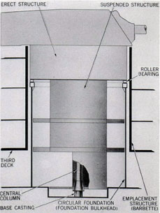
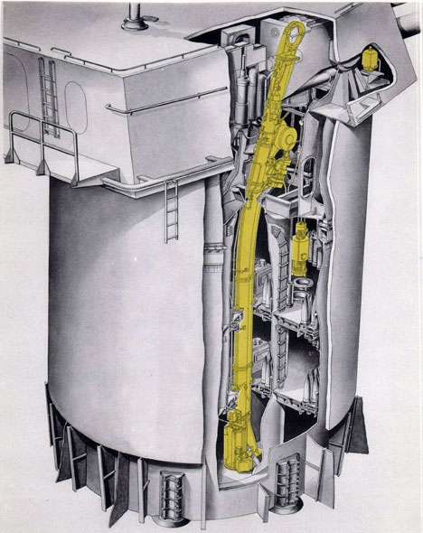
The three large units comprising the structural assembly are the fixed and movable parts designated in the profile diagram of figure 1. They are a circular foundation, a rotating structure, and a roller bearing between the two.
The circular foundation consists of parts built into the ship to support and protect the rotating structure. These parts are the foundation bulkhead, barbette, and other fixed elements described on pages 10-13.
The roller bearing is the turret roller bearing assembly described on pages 8-10.
The rotating structure is the part that is seated on the bearing and that mounts and encloses all the ordnance mechanisms and auxiliary installations. This rotating structure is the armored gun house, the structure beneath the gun house, and the attached hatches, doors, ladders, trusses, and special devices described in the paragraphs which follow.
Rotating structure
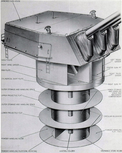
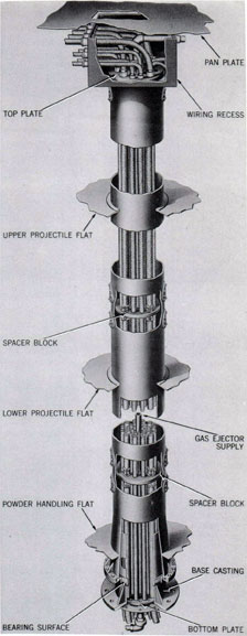
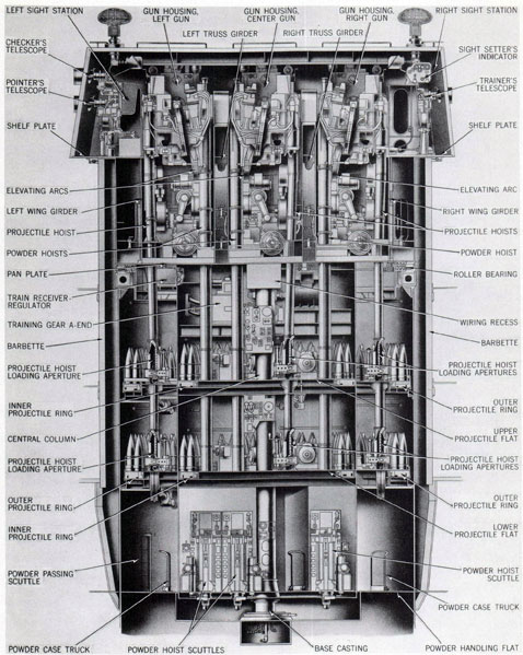
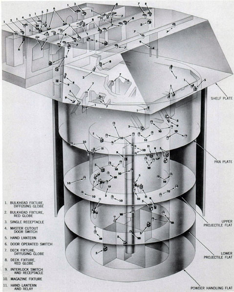
The rotating structure is a steel weldment nearly 45 feet high, weighing 270 tons, consisting principally of the structural plates identified in figure 2. It is a five-story structure erected in the form of a rectangular gun house above a cylindrical assembly of four flats.
The plates identifying the five levels are: the shelf plate at the bottom of the gun house, the pan plate at the bottom of the gun pits, two levels called the upper and lower projectile flats, and, at the lowest level, the powder handling platform. These plates are joined together by a cylindrical bulkhead and gun girders between the shelf and pan plates, a id another cylindrical
Figure 1. Turret Structure Fixed and Rotating
Elements
1
Figure 2. Turret Subdivisions and Principal
Structural Units
2
bulkhead and a central column extending from the pan to the powder platform. The column, both bulkheads, and the outer edges of all floor plates below the shelf plate are concentric with the turret center of train rotation. This arrangement-and the welded construction of all plates, girders and bulkheads-ties the entire rotating structure together in one rigid unit. It divides the turret into its principal functional spaces of gun compartment and ammunition handling compartments. Those spaces are within the following over-all measurements:
Dimensions, Rotating Structure
Vertical distances:-
Powder platform to lower projectile flat
10 ft.
Lower projectile flat to upper projectile flat
7 ft. 6 in.
Upper projectile flat to pan plate
9 ft. 7 in.
Pan plate to shelf plate
8 ft. 7 in.
Shelf plate to turret roof plate
9 ft.
Gun house length
32 ft. 10 in.
Gun house width
30 ft. 8 in.
Diameter at pan plate
24 ft. 3 in.
Upper projectile flat diameter
22 ft. 10 in.
Lower projectile flat diameter
22 ft. 10 in.
Powder handling platform diameter
14 ft. 4 in.
Central column diameter
22 in.
Lower circular bulkhead diameter
14 ft. 4 in.
Gun house structural plan
The space enclosed between the gun house roof and the pan plate is not subdivided by flame barriers. This 17-foot high gun and gun pit compartment is formed and partially subdivided by the following design arrangements.
Gun pit details. Extending vertically above the pan plate (and supported by it) are five major components of the turret. These are the enclosing circular bulkhead and four gun girders. The latter are longitudinally parallel, vertical units dividing the gun pit into three pockets.
All gun pockets are approximately the same size: each is ten feet deep and seven feet wide, and the average length within the curving end walls is 22 feet. The gun girders that form their parallel sides are different design types; the outer, or wing, girders are plate structures; the center units are truss girders.
Wing girders isolate two small spaces between their outboard sides and the circular bulkhead. These are called the pan plate wing chambers, left and right. In each a series of vertical plates, transversely placed and welded between the bulkhead and the girder, stiffen the girder and the pan plate. These details and the arrangement of access openings in each plate girder and within the wing compartments are shown in figure 3.
Truss girder details are also illustrated in figure 3. Each is a weldment of two parallel plates with web bracing and stiffening plates. They are transversely stiffened with box structures at the front, extending from wing girder to wing girder. In the interior open spaces of both truss girders, electric cabinets, hydraulic system tanks, and other equipment are mounted. These installations fill the trusses-except for personnel passages between pockets, at the rear.
All four girders extend above the shelf plate to the level of an elevated floor of the gun house. The forward portion of each has two structural extensions that extend nearly to the
Figure 3. Gun Girder Construction
3
turret roof plate. These extensions are shown in figure 3. One is a seat for a deck lug bearing; the other is a support for a curved guide rail that is an element of the ammunition hoists described on pages 37-41.
Gun house details. The shelf plate is welded to the above-described gun pit structure, resting on the circular bulkhead and abutting the two wing girders. It extends outboard beyond the circular bulkhead, overhanging slightly at the front and sides and nearly nine feet at the rear. It is cut away in the area between the wing girders, providing a clear opening above all three gun pits.
Parallel with the shelf plate and elevated 18 inches above it, are floor plates. These form a continuous floor throughout the gun house, including the top plates of the truss girders, except for the gun pit area and two depressed control station areas, one at the right side and one opposite at the left side.
In the space under the floor, floor beams and stiffening plates, together with the shelf plate, form a rigid box structure. This structure is designed to receive and support the gun house armor at its outer edges, and, in the space between shelf and floor plates, to accommodate units of the ventilating system described on pages 52-55.
Three transverse arch-beams rise from the shelf structure and extend across the gun pits,
Figure 4. Gun Port Arrangement
Figure 5. Gun Port Gas and Water Seal Details
six feet above the floor level. These large structural columns and beams .are armor plate supports. With the shelf structure and the armor plates, they constitute ,the entire gun house structure.
Armor. The armor plates consist of nine pieces shaped, fitted, and welded together to form an integral structure. Their identities and thicknesses are:
Face plate
8 inches
Front side plates, right and left
3.75 inches
Rear side plates, right and left
2 inches
Rear plate
2 inches
Roof plates, front, center, rear
4 inches
Figure 2 shows the assembled form of the armor plates and details of the attached foot
4
and hand rails, ladders, and platform. Face and side plates slope inward; the rear plate is vertical. Attached devices and the openings in the armor differ for the three turrets; the arrangements of the illustration, for turret II, are the most extensive.
The armor openings of turrets II and III are the same. Each has 13 openings. These are: three gun ports, three sight hood openings, two periscope and two antenna openings, and three access doorways. Turret I openings are the same, except for omission of the antenna holes in the roof plate. Access doors in all turrets are located in the rear plate. These and all other
openings, with exception of the gun ports, are fitted with conventional gasket seals or fabric bucklers. They are arrangements that make the gun house a weather and gas sealed enclosure.
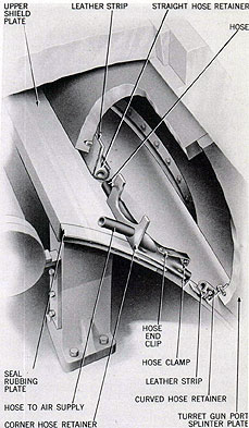
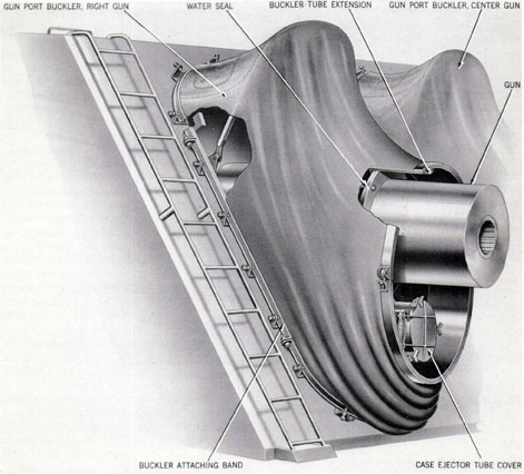
Gun ports. Arrangements for sealing the three gun ports are fixed and moving and inflated elements of special design. They are the arrangements illustrated in figure 4. These consist of a weldment of splinter plates on the rear side of the face plate, a mating shield plate on the gun slide, an air hose sealing device, and, on the exterior, a large fabric buckler.
Figure 5 shows the details of the special gun port gas and weather sealing device. This device
Gun Port Buckler
5
is a leather strip that encircles the edge of the splinter plate weldment and bears on the surface of the moving gun port shield. A rubber hose, distended by compressed air, is secured in special fittings and clamps, so that it presses against the leather strip to assure mechanical seal. Air supply for this seal is tapped from the gas ejector system described on pages 67-68.
Figure 6 shows the details of the buckler. It includes a steel weldment called a buckler tube extension, mounted on the gun slide. This unit has a water seal between the extension and the recoiling surface of the gun. A laminated fabric buckler* is clamped to this tube extension and also to a buckler attaching band bolted on the face plate.
Gun house subdivision. No bulkheads subdivide the interior of the armored enclosure, but pipe stanchions and rails enclose the rear and two sides of the gun pits. On the rear line of stanchions and rails are mounted many control instruments and devices. These form a partial bulkhead separating the gun compartment from the turret overhang space called the turret officer's booth.
Access passage between the booth and wing spaces and the gun pits is provided by the following arrangements. Left and right sight control station areas are directly accessible from the booth by narrow walkways at the sides of the gun pits. Similar narrow walkways along the tops of the two truss girders are unobstructed by doors and give access passage from the booth into the gun compartment. Ladders at the rear of the gun pits permit passage between the booth and the pan. At the left side, a floor hatch and ladder give access to the left wing compartment of the pan and thence to the forward part of the left gun pocket.
Suspended structure
The portion of the rotating structure extending below the pan plate is a suspended structure that is isolated from the gun house and gun pits except for conventional flame-tight hatches in the pan plate, one at the rear center and two forward. This structure consists
* Tentative material; actual specification of this material or alternate leather buckler not provided at date of this publication.
of the three lower levels of the turret. It is suspended from the pan plate and the upper roller path.
Upper roller path. The upper roller path is a large forged steel ring, 24 feet in diameter, secured under the pan plate and the circular bulkhead and concentric with the train axis and the cylindrical structure. It is the upper race of the turret roller bearing. The bottom face is a precisely milled horizontal surface 13 feet below the gun trunnion axis. From this bearing surface, the suspended structure hangs 27 feet to the level of the powder flat.
Suspended structure details. The main units of the suspended structure are the lower circular bulkhead, the central column, the upper and lower projectile flats, and the powder handling platform.
The column and the bulkhead are continuous steel cylinders fastened to the pan plate and extending through and supporting all three floor structures. On each level the bulkhead has cutaway sections. These provide access archways through the cylinder on the two projectile flats and form an open sector for part of the powder handling platform. A straight bulkhead, built-in with the ammunition hoists described on pages 37-41, encloses the remaining portion at the bottom level. This forms a semicircular compartment that is partitioned into three small storerooms, flameproofed from the surrounding powder handling space and from each other. Although they are identified as "storerooms," these three sub-compartments are primarily fire-hazard safety spaces. They are flame isolating chambers. Each confines the downward flame and explosion of a powder hoist fire, permitting limited expansion but blocking the fire hazard from the other hoists, the powder handling space, and the magazines. This purpose limits the type and amount of storage permitted in the three chambers to noninflammable tools and accessories of small volume.
Both the upper and the lower projectile flats / are identical in compartment subdivisions and space arrangements. The circular bulkhead separates each flat into an inner circular compartment, and an outer ring-shaped space. The latter is 23 feet in diameter and is enclosed by the foundation bulkhead of the fixed structure.
6
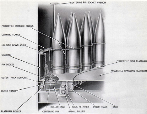
Figure 7. Projectile Ring Arrangement
In the floor of both compartments are roller-mounted circular platforms. These are at the outer limits of each space and concentric with the central column and the circular bulkhead. They are rotating platforms that are power-driven by the equipment described on pp. 49-50. The top surface of each is flush with the adjacent floor plates of the flat. These units are projectile stowage platforms called projectile rings. Each is an integral platform weldment with an enclosing circular coaming, arranged with chain lashings and other details as illustrated in figure 7. The platforms are 16.75 inches wide and their outer diameters are 14 feet 1.5 inches and 22 feet 11 inches for the inner and outer rings respectively. Their projectile capacities and other data are included with the descriptions of the ordnance installations on pages 19-21.
A cross web of heavy I-beams, passing through the circular bulkhead, supports the floor plates and the two stowage rings of each projectile flat. It is an exceptionally heavy floor-beam construction, cross-braced by other beams, stiffened by the platform plates, and designed to carry the large floor loads and particularly the cantilever outer ring loads without apparent deflection.
The structural details of the upper flat include a major difference. In the inner compartment a heavy transverse platform, in the forward sector, extends across the compartment above the projectile ring. This is a supporting platform for mounting some of the units of the train power drive.
Access facilities between the projectile and powder flats are vertical ladders located under hatches at the rear of the turret. These hatches
7
in the projectile flats are vertically under the rear flame-tight hatch of the pan plate. Together they provide a clear hoist strike, for removing and installing equipment, between the gun house and the powder handling compartment.
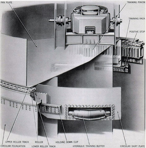
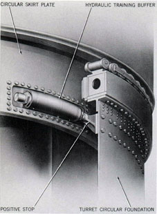
Skirt plate. A cylindrical plate hangs from the bottom of the pan plate into the projectile stowage space of the outer compartment of the upper projectile flat. This is called the cylindrical
skirt plate. It is a functional element of the turret turning installation and not a structural member. On it are mounted the units that hold the rotating structure down and that buff the turning movements at train limits. These parts are the holding-down clips and the hydraulic training buffer identified in figure 8.
Turret roller bearing
The rotating structure turns on the roller
Figure 8. Turret Roller Carriage Arrangement
8
Figure 9. Cage Sector and Roller Spacing Details
bearing assembly shown in figure 8. This unit is a conventional turret bearing design. It is supported on a lower roller track unit of the fixed structure described on the next page.
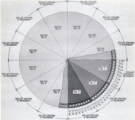
Bearing components. The bearing consists of 96 rollers assembled in 12 cage sectors that are attached together by butt straps to form a 360° bearing ring. Its outside diameter is slightly more than 24 feet.
Rollers. All rollers are identical. Each is a tapered roller of forged steel with integral flanges, 10.5 inches across flanges, 6.75 inches maximum diameter (at the inner flange) , providing linear contact of eight inches on the
roller tracks of the upper and lower races or roller paths. Each roller is drilled, bushed, and fitted with a spindle bolt. This bolt locates and retains the roller in a precisely allotted position in the cage sector.
Cage sectors. The twelve cage sectors are alike as to construction, but differ as to the assembled positions of the eight rollers retained by each. This difference applies to variations in the spaces between the axes of the 24 rollers of a quadrant; all four quadrants are alike. Thus in each quadrant of three 30° sectors, the spaces between rollers vary by increasing increments that are constant for each sector but differ
9
Figure 10. Lower Roller Path, Training Buffer and
Train Stop Arrangement
in value for the three sectors. The spacing data of a typical quadrant are indicated in figure 9. In sector No. 1, the distances between rollers increase clockwise by increments equal to four minutes of arc, in sector No. 2 by six minutes of arc, and in sector No. 3 by eight minutes of arc. The design arrangement is for the purpose of preventing "brinelling," or roller path deformation, from developing at the points of linear contact-a condition that would develop under firing and sea-way load stresses if all spaces were equal.
Roller access. The arrangements of the cage sectors and the turret structure provide for inspection, lubrication, and replacement of rollers without dismantling the turret. Holes in the cylindrical skirt plate permit access to any and all rollers from the upper projectile flat by turning the turret. To remove a roller, the inner ring of any cage sector can be unbolted and lowered into the projectile flat. By similarly removing the holding-down clips, the turret
may be jacked until the roller flange can clear the tracks, sliding the roller from the spindle bolt without disturbing the outer cage ring or spindle.
Fixed structure
The fixed, or nonrotating, turret structure consists of the circular foundation, lower roller path, powder handling flat, base casting, and barbette. Their form and relative positions are indicated in figure 1.
Turret circular foundations. Turret circular foundations differ for the three turrets. Each is a large cylindrical steel weldment, 23 feet 8 inches in diameter, supported and secured at the ship's second platform. For turret I this cylinder extends upward 25 feet 2 inches above the second platform; for turret II, 33 feet 3 inches; and for turret III, 24 feet 2 inches.
Each circular foundation is a stand for the lower roller track unit. See page 11. In addition, it is an enclosing bulkhead for the projectile and powder handling compartments and provides attached elements that function with the arrangements of those compartments and the turret turning mechanism. These elements are training stops, flame seals, and powder scuttles.
Two training stops are located near the top of the foundation in the way of the training buffer, as shown in figures 8 and 10.
Two flame seals isolate the ammunition flats. They are angle brackets formed into complete rings. Each is mounted on the bulkhead so that it mates with a complementary ring at the bottom of a projectile flat. This combination provides a mechanical barrier between the compartments, but permits free turning of the turret.
Six powder passing scuttles and two access doors are located in the bottom section of the bulkhead. These are communications arrangements between the powder handling room and the magazines. Scuttles are vertically positioned cylinders, each with two powder cartridge chambers. They are manually rotated units that transfer powder cases (without tanks) from the
magazines to the handling room and maintain
mechanical seal between the turret and magazine compartments.
10
Powder handling flat. At the bottom of the circular foundation, a ring-shaped floor structure forms the powder handling flat. The floor plates of this flat are flush with the powder handling platform of the rotating structure. They provide a powder case truck maneuvering area nearly five feet wide in front of the six magazine scuttles, which are equally spaced in the foundation. Thus, at all positions of turret train, three scuttles are conveniently accessible to the open sector of the revolving platform (and the hoists), and rapid passing is possible without traffic interference.
Lower roller track. The lower roller track an assembled ring-shaped weldment of box-section. Its form and construction, and its riveted attachment at the top of the foundation, are illustrated in figure 10. Two surfaces are precisely milled after the ship is launched. The top or roller track is a bearing surface of the same form, finish, and size as the similar surface of the upper roller track (24 feet in diameter). The inner vertical face is a true cylindrical surface, concentric with the roller paths and the axis of the rotating structure. It is keyed and tapped for accurately seating the sections of a large annular rack called the training circle. This rack is a 360° gear of 196 teeth and 256-inch pitch diameter. It is the fixed gear of the turret turning drive described on page 29.
Base casting. The lowest element of the fixed structure is the base casting. This part is a large flanged and hollow pintle, of 22.5-inch diameter, 3 feet high, that is secured below the second platform and is accurately centered beneath the turret center of rotation. It is a dual purpose element, functioning to align the rotating structure and to lead-in the communications, power, and air supply. It extends into and provides a radial bearing for the lower end of the central column. A circular plate, horizontally positioned at the bottom and drilled in a pattern of equally spaced holes, separates the cables and prevents them from chafing. These features are shown in figure 11.
Barbette. The barbette is an assembled cylinder of heavy armor plate consisting of seven cylindrical segments. These are joined by dovetail keys and, at the abutting decks, by deck
Figure 11. Base Casting and Central Column
Wiring Tube Arrangements
11
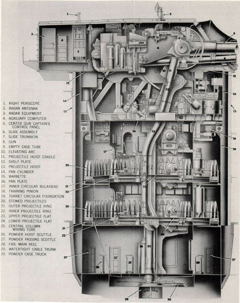
Figure 12. Turret General Arrangement, Longitudinal Section
12
seam straps, the whole forming a built-in unit that encloses all of the turret that is not protected by the belt, deck, and gun house armor. Its outside diameter is 27 feet. It extends vertically upward from the third deck, through the second and weather decks and above the latter to a plane one inch below the shelf plate. Thus the three barbettes of the ship have different heights because of the different heights of the foundation bulkheads and the positions of the roller tracks with respect to the weather deck. For turret I this barbette dimension is 19 feet; for turret II 27 feet 5 inches; and for turret III 20 feet.
Barbettes differ also in thicknesses of plates. The standard thickness is 6.3 inches for the entire perimeter of turret III and for six plates each of turrets I and II. One plate each of the barbettes of turrets I and II is 5.5 inches thick. These are the opposing 45° segments of those barbettes.
All barbettes are supported at their lower edges by large, heavy steel plate, flanged brackets that are attached to the outside of the respective turret circular foundation. These brackets are entirely below the armored, third deck and are in the respective powder magazine compartments. This construction of supporting brackets is otherwise stiffened and braced by weldment of the abutting deck seam straps and other details at the juncture of the barbettes with the three decks.
The space within the barbette brackets, between the circular foundation, the brackets, and the barbette, is isolated from the magazines. But it has portable plate access to ladders on the outside of the foundation. These provide access to the exterior cage sectors of the turret roller bearing.
ORDNANCE INSTALLATIONS
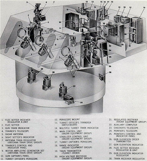
The ordnance installations mounted in the turret rotating structure described in the preceding text consist of the units identified and arranged as shown in the vertical sections of the turret, figures 12 and 13, and the turret floor plans of figures 14 to 21 inclusive. These installations comprise the following types of equipment.
Ordnance types. Each turret ordnance assembly consists of units of the following types:
Gun equipment
Gun laying equipment
Ammunition hoists
Ammunition stowing equipment
Ammunition handling equipment
Fire control equipment
Turret ordnance assembly differences. The several types of equipment are identical turret assemblies in all turrets, with exception of the fire control equipment of turret I. In that turret, the radar assemblies and certain instruments associated with turret local control are omitted.
Turret ordnance design identities. The equipment of the above types comprising each turret assembly includes one or more units of the following 8-inch Ordnance design identities, with exception of the omissions mentioned in the preceding paragraph.
GUN UNITS, 8-INCH
Gun Mk 16 Mod 0
Housing Mk 1 Mods 0 and 1
Gas Ejector Mk 16 Mod 0
Slide Mk 20 Mods 0 and 1
Rammer Mk 18 Mods 0 and 1
Case Ejector Mk 1 Mods 0 and 1
Slide power equipment
Deck Lug Mk 18 Mods 0 and 1
GUN LAYING EQUIPMENT, 8-INCH
Elevating Gear Mk 23 Mods 0, 1, and 2
Training Gear Mk 22 Mod 0
AMMUNITION HOISTS, 8-INCH
Projectile Hoist Mk 31 Mods 0, 1, and 2
Powder Hoist Mk 36 Mods 0 and 1
AMMUNITION STOWING EQUIPMENT, 8-INCH
Projectile Ring Mk 1 Mod 0
AMMUNITION HANDLING EQUIPMENT, 8-INCH
Parbuckling Gear Mk 1 Mod 0
FIRE CONTROL EQUIPMENT
8-inch Sight Mk 32 Mod 0
8-inch Elevation Gun Attachment Mk 7 Mods 0, 1, and 2
8-inch Training Gun Attachment Mk 7
Mod 0 Fuze Setter Mk 20 Mod 0
8-inch Firing Circuit Mk 8 Mod 0
Train Receiver-Regulator Mk 25 Mods 0, 1, and 2
13
Figure 13. Turret General Arrangement Transverse Section
14
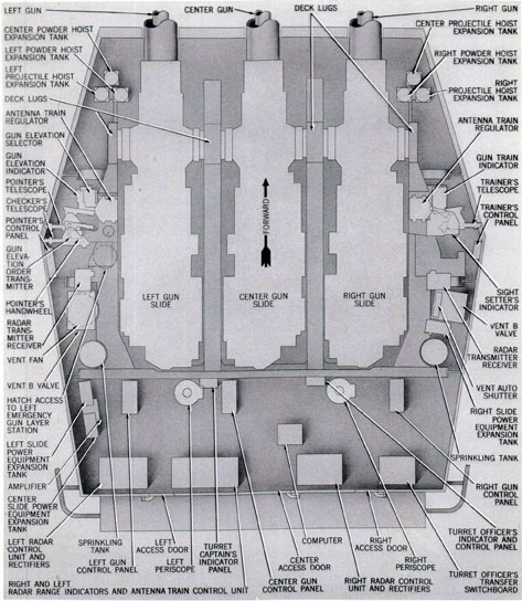
Figure 14. Gun House Ordnance Equipment. Plan View
FIRE CONTROL EQUIPMENT (CONTINUED)
Gun Elevation Indicator-Regulator Mk 47 Mod 0
Error Reducer Mk 1 Mod 0
Fuze Setting Receiver-Regulator Mk 1 Mod 1
Radar Equipment Mk 27 Mod 0
Antenna Train Drive Mk 5 Mod 0
15
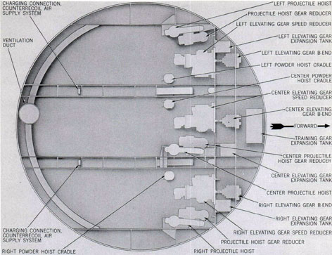
Figure 15. Ordnance Equipment Above Pan Plate. General Arrangement. Plan View
FIRE CONTROL EQUIPMENT (CONCLUDED)
Computer Mk 3 Mod 9
Multiple Turret Train Indicator Mk 12 Mods 7 and 9
Gun Elevation Indicator Mk 45 Mod 0
Gun Train Indicator Mk 25 Mod 7
Gun Elevation Order Transmitter Mk 4
Mod 0 Sight Setter's Indicator Mk 8 Mod 0
Turret Train Order Transmitter Mk 14
Mod 1 Periscope Mk 20 Mod 5
Periscope Mount Mk 5 Mod 15 Telescope Mk 53 Mod 1
Telescope Mk 98 Mod 0
Telescope Mk 99 Mod 0
Turret ordnance assembly references. The exact number and identity of each of these components of the turret assemblies are listed in
the tabulations of 8-inch Turret Assemblies appended at the back of this book. These listings include references identifying the Fire Control Equipment Sketch Lists of Assemblies and the Turret Ordnance Equipment Sketch Lists of Assemblies for every turret installation of CA 139 class.
Turret ordnance location arrangements. All ordnance items listed on pp. 13-16 are mounted in the rotating structure as indicated in the ensuing description of the five floor levels.
Gun house ordnance arrangement. Figure 14 shows the location arrangements of all ordnance equipment in the gun house, with exception of the sight and gun attachment shaft transmission systems. These are located at the front above the guns, transversely spanning the compartment, and under the floor at the
16
sides and rear of the gun pits. In addition to the ordnance installations, the picture also shows the positions and relative sizes of some large elements of the ventilating and sprinkling auxiliary installations described on pp. 52-60.
In the gun house are located all units of all three guns, except the forward portions of the barrels and the power plants of their slide power equipments The latter are located two levels below.
Other principal units in this space are components of the fire control equipment. They are grouped in three locations; trainer and sight setter controls at the right side, pointer and checker controls at the left side, and controls for the turret officer, the turret captain, the three gun captains, the radar control operators, and the computer operators in the booth over the overhang at the rear of the compartment. Many elements of these controls are mounted
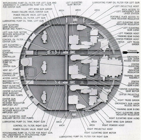
Figure 16. Ordnance Equipment on Pan Plate. General Arrangement. Plan View
17
Figure 17. Ordnance Equipment Above Upper Projectile Flat. General Arrangement. Plan View
on panels under the rear transverse roof girder and are not shown in the figure. They are identified in the descriptions of the fire control arrangements on pages 43-45.
Gun pits ordnance arrangement. Figures 15 and 16 show the location arrangements of all ordnance equipment in the gun pits; units immediately under the guns are designated in figure 15, while those on the pan plate or on platform structures are located just above the pan in figure 16.
In the gun pits are located all components of three elevating gear drives and their indicator-regulator controls, parts of the training gear drive, the upper ends of six ammunition hoists,
three fuze setters and fuze setting regulators, electric controller cabinets, and many tank and other devices. of the elevating and training gears. Many of these units are mounted within the void spaces of the two truss girders.
Two important access hatches are indicated in figure 16. These are control station hatches giving access to the emergency gun laying stations for the right and center guns. They are reached by ladders from the upper projectile flat. The similar station for the left gun is manned from the gun house via a hatch indicated in figure 14 and thence through the left wing girder compartment and the archway designated on figure 16.
18
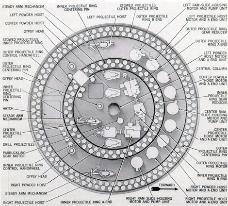
Upper projectile flat ordnance arrangement. Figures 17 and 18 show the location arrangements of all ordnance equipment and of stowed ammunition units in the upper projectile flat compartments. Figure 17 designates the units that are above the floor and overhead; figure 18 those on the floor.
In the inner compartment of this space are four ammunition hoists, three principal units of the training gear drive, eight electric power cabinets, a large hydraulic oil reservoir, and a motor, pump, and tank of a training gear lubricating system, all as shown in figure 17; also
two projectile ring drives, a parbuckling gear motor, gypsy head, and steady arm mechanism, 74 service projectiles, and three drill projectiles, as identified in figure 18.
In the outer compartment are two ammunition hoists, a whip hoist, two large hydraulic reservoirs, training gear control motor, receiver-regulator and main driving pinion, as indicated in figure 17, and, nine power plants for hoists and slide equipment, two parbuckling gypsy heads, two steady arm mechanisms, and 151 service projectiles and four drill projectiles, all as shown in figure 18.
Figure 18. Ordnance Equipment on Upper Projectile Flat
General Arrangement. Plan View
19
Figure 19. Ordnance Equipment Above Lower Projectile Flat
General Arrangement. Plan View
This congested flat has clear areas for handling projectiles in the immediate vicinity of the three projectile hoists only.
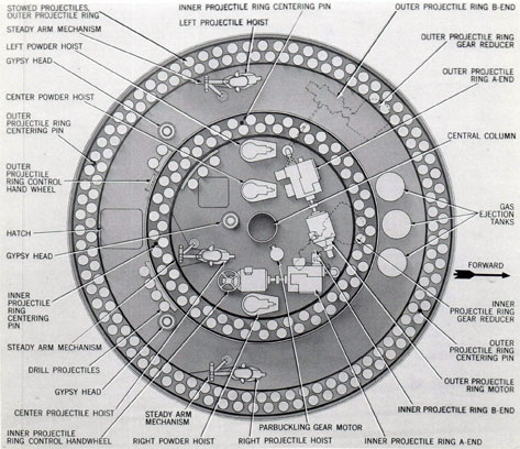
Lower projectile flat ordnance arrangement. The arrangements of the lower projectile flat are similar to those of the upper flat with respect to the ammunition hoists, parbuckling gear, and projectile ring installations. Projectile stowage is the same, with the exception of one additional drill projectile. These arrangements and the following differing details are indicated in figures 19 and 20.
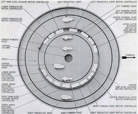
In the inner compartment, 15 electric controller cabinets are mounted on the circular bulkhead over the projectile stowage, as shown in figure 19. These comprise all of the ordnance
power drive controllers except the elevating and training gear drive controllers, which are in the gun pits (fig. 16).
In the outer compartment, three large relay tanks of the gas ejector air supply system are mounted in the forward quadrant. This compartment has space for stowing 40 additional projectiles in the forward sectors, but the initial turret designs do not include stowing brackets and lashings.
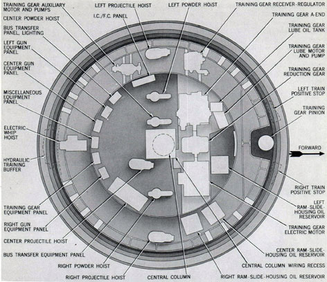
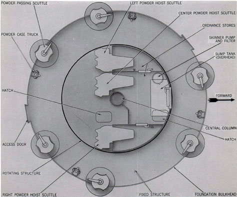
Powder handling flat ordnance arrangement. Figure 21 shows the arrangements at the bottom of the turret. These include three powder hoists and their loading scuttles, and six magazine scuttles.
20
This picture also indicates three compartment subdivisions in the rotating structure.* These are miscellaneous store rooms for powder drill cases, turret tools and accessories, and an oil clarifying plant. The latter is a Skinner pump, filter, tanks, and pipe system for flush-cleaning the hydraulic drive units and purifying the hydraulic fluid.
Ordnance designs
The installation arrangements described on pages 22 to 26 include design features, details
*For an explanation of this compartment and structural arrangement, see page 6.
of construction, and functional relations of equipment controls that adapt the assemblies for continuous automatic fire. These are mechanical, electrical, and hydraulic operating and controlling devices which enable the guns to be separately served and loaded but provide for different methods of selective control of all guns and the turret, so that the turret is controlled as a unit. They constitute new turret operating and coordinating systems. The features of each type of assembly that provide these characteristics are briefly indicated in the descriptions beginning on page 22.
Figure 20. Ordnance Equipment on Lower Projectile Flat
General Arrangement. Plan View
21
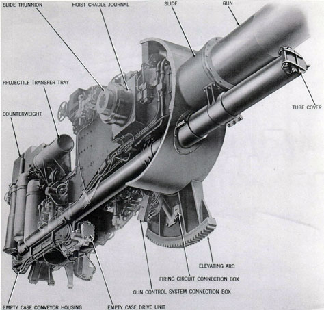
Gun and slide assemblies
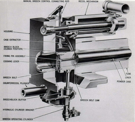
Figures 22, 23, and 24 show the assembled arrangements of a typical gun. This unit consists of a gun, gun housing, gas ejector, slide, rammer, and case ejector.
Gun. The gun is a two-piece 8-inch/55-caliber design consisting of a tube and a rifled liner. It is a "loose" assembly, the liner being fitted for convenient removal and replacement on board ship. Powder chamber and breech designs provide for pre-loaded semifixed ammunition.
Figure 21. Powder Handling Flat. General Arrangement Plan View
22
Figure 22. Gun and Slide Equipment. General Arrangement
Bottom View
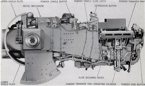
Gun housing. The breech mechanism is a sliding block type similar to the 6-inch/47-caliber light cruiser gun arrangements. It includes hydraulic power cylinder and manual operating devices, as shown in figure 25. The unit is part of the large steel forging designated "housing" which is attached on the gun shoulder and rear cylinder by a bayonet-type joint.
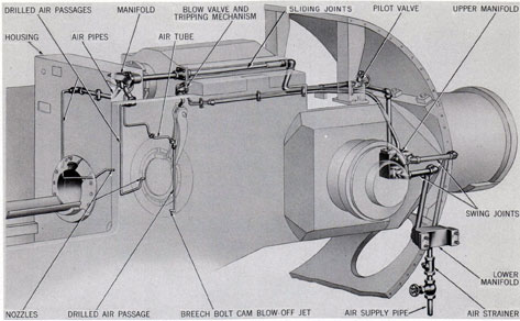
Gas ejector. Internal air leads and nozzles of the housing and connecting air lines and air porting
valve on the slide comprise the gas ejector system. Their arrangements are shown in figure 26. This system is entirely automatic, porting air to the breech nozzles when the case extractors operate and cutting off flow according to time-setting of a pilot valve.
Slide. The gun slide is a loading-tray type. It supports the gun and housing in a cylindrical bearing and two parallel rails. It controls gun recoil through a hydraulic cylinder unit as
23
Figure 23. Gun and Slide General Arrangement
Right Side
Figure 24. Gun and Slide General Arrangement
Left Side
24
Figure 25. Gun and Housing Arrangement
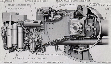
shown in figure 25, and returns the gun to battery by means of a conventional hydropneumatic counterrecoil cylinder unit. Its loading-tray design includes two large tubular transfer trays, hinged and operated by hydraulic cylinders arranged as shown in figures 23 and 24.
These trays fold inboard into ramming position in alignment with the bore and a power-operated folding chain rammer. The power unit is a hydraulic motor, mounted at the rear and coupled to a large chain sprocket.
The powder transfer tray of this loading tray arrangement has an attached tray that is mounted on curving rails. This tray is called an
empty-case tray. In firing position it is aligned with the bore and receives extracted empty powder cases. When the transfer trays move to loading position for ramming the next round, the empty-case tray dumps the empty case into a compartment at the rear and bottom of the slide. In the floor of this compartment is an endless chain conveyor, driven by a hydraulic motor, arranged as indicated in figure 22. This conveyor thrusts the empty case into a tube that extends through the gun port shield and the front of the turret.
The slide is pivoted by means of trunnions in roller bearings supported in deck lugs that are
25
Figure 26. Gas Ejector System. General Arrangement
attached to gun girder extensions illustrated in figure 3. In this position, the entire assembly of gun and slide is balanced, and the elevating arc indicated in the pictures is meshed with a spur pinion of a speed reducer of the elevating gear mechanism.
The trunnion arrangements of the slide include journals for mounting two cradle units. These are elements of the ammunition hoists described on pages 37-41.
Slide power equipment. The breech mechanism, the transfer trays, and the rammer and case ejector hydraulic operating units receive hydraulic power for performing their actions from a hydropneumatic accumulator. This unit consists of the large vertical cylinder and two air flasks mounted at the side of the slide as shown in figure 23. It is connected by an extensive system of hydraulic pipes to all operating units and to a pump that is mounted with its electric motor on the upper projectile flat, as shown in figure 27. A feature of this power operating arrangement is continuous delivery of power, throughout the periods of all gun loading and gun firing actions.
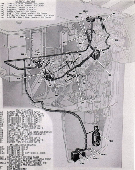
Slide equipment control system. Hydraulic power operations of the gun units are controlled by an electric installation of switches and solenoids. These are limit and interlock switches and valve operating solenoids on the breech, rammer, tray and case ejector mechanisms, and control switches of a gun captain's control panel. The latter is mounted at the rear of the gun in the turret officer's booth. Its interconnecting system of wire circuits to the slide switches and solenoids, and the identities and functions of the latter, are indicated in figure 27. This system enables all loading and firing actions to be performed without attendants in the gun compartment and without stopping gun laying. It is part of the system which controls the hoists as well as the slide, breech, and rammer. This system is called the gun loading control system.
Gun laying equipment
Figures 28 to 34 inclusive show assembled arrangements of the turret turning mechanism and typical gun elevating drives and their controls. These units consist of the training gear
26
Figure 27. Gun Control System. General Arrangement
27
Figure 28. Training Gear. General Arrangement
28
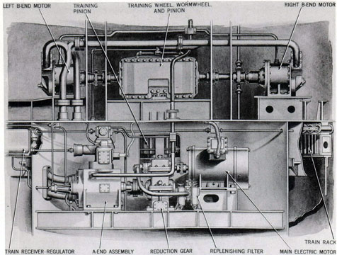
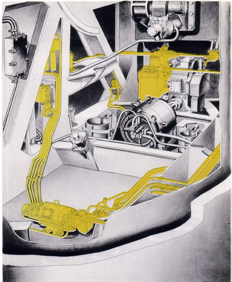
Figure 29. Training Gear Power Drive. General Arrangement
electric-hydraulic drive equipment, train receiver-regulator, and control station equipment for the turret turning system; and three elevating gear assemblies, three gun elevation indicator-regulators, and one pointer's control station equipment for the gun elevating system.
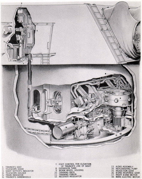
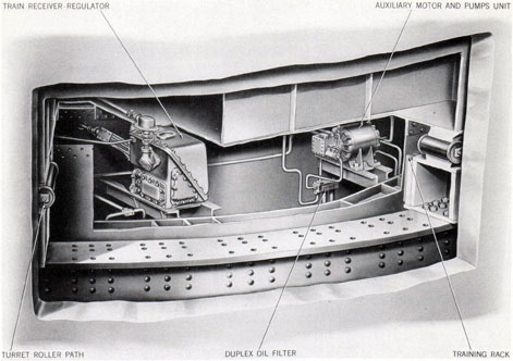
Training gear. The training gear is a worm, wormwheel, and pinion mechanism meshed with the large fixed circular rack on the lower roller track and driven by an electric-hydraulic power drive. Its installed arrangements at the front of the turret are shown in figure 28, and the components and arrangements of the power drive assembly in figure 29.
The drive consists of a 125-horsepower electric motor coupled to a large reduction gear which drives a Waterbury A-end pump assembly. The valve-plate of the latter is connected hydraulically to two Waterbury B-end motors
by a system of large pipe manifolds-an arrangement that delivers equal volume and equal fluid pressure to both hydraulic motors. Motors are coupled at opposite ends of the driven worm. Thus drive torque is the same at both ends of the worm.
Training gear control. Hydraulic fluid delivery to the B-end motors is controlled by varying the displacement of the A-end pump. Three methods are provided for controlling this output. Two are hydraulic power servo control selections, the third is a manual mechanical control method.
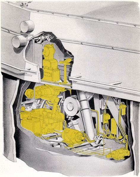
The servo control methods are provided by the receiver-regulator instrument and its auxiliary hydraulic power supply unit shown in figure 30, and by a stroking cylinder device on the A-end pump. These units operate in response to signal inputs to the regulator instrument.
29
Figure 30. Train Receiver-Regulator and Auxiliary Power Unit
Turret Arrangement
The latter amplifies the signal and ports an equivalent amount of servo fluid to the stroking cylinder to cause the A-end to deliver an equivalent amount of drive fluid to the B-end motors. This action can be controlled by receiving an electrical signal from a remote director or by receiving a mechanical signal from the trainer's handwheels. These methods are called AUTO and LOCAL control respectively.
The third method of control is called HAND. It does not use the servo control units. It controls the A-end pump output by mechanically stroking the pump tilting device through direct connection with the trainer's handwheels.
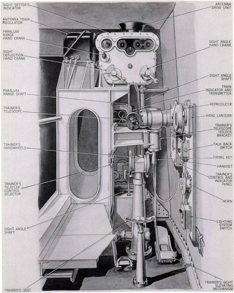
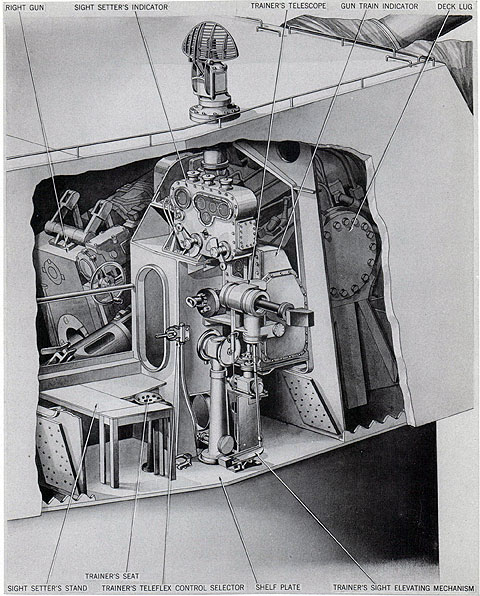
Trainer's control equipment. The control devices at the trainer's station that enable him to start and stop the drive, to select the method of control, and to control turret turning in LOCAL and HAND control are identified in figure 31. They are the control and indicator
panel, the control selector, the handwheels, the train indicator, and the sight. The manner in which they are employed in the different methods of control is explained in Chapter 2; their arrangements are as follows:
The control and indicator panel is an electrical cabinet containing the power drive master switch and six indicator lights. By means of the master switch the main and auxiliary electric motors are started and stopped. Indicator lights show the conditions of power supply circuits for the regulator instrument as well as the power drive and include "ready," "neutral," and "stop" indicators.
The control selector is a manually operated lever that has three positions, designated, HAND, LOCAL, and AUTO, respectively. It actuates a flexible cable that is connected to a device at the regulator which positions a selector valve of that instrument.
30
Figure 31. Trainer's and Sight Setter's Station
General Arrangement
31
Figure 32. Elevating Gear General Arrangement
32
Figure 33. Turret Arrangement of Elevation Indicator-Regulator and
Auxiliary Power Unit
33
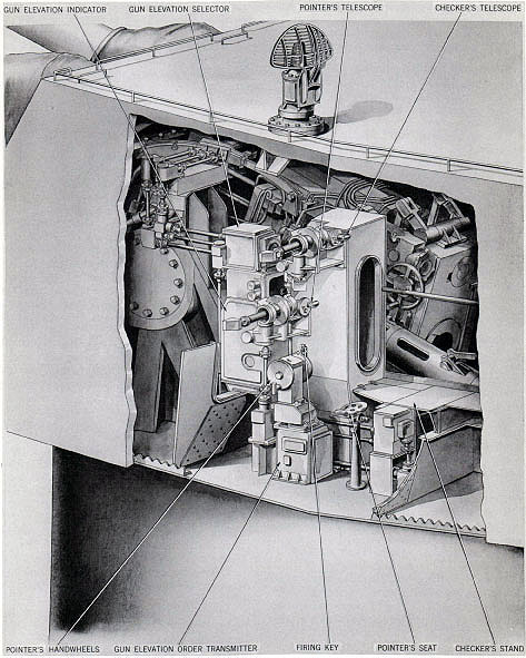
Figure 34. Pointer's and Checker's Stations
General Arrangement
34
The handwheels are part of a conventional hand control gear that extends to mechanical inputs at the A-end assembly and the regulator. These are clutched and unclutched hydraulically for the respective control selections by shifting of the selector valve and other control valve units.
The train indicator is a gun order follow-the pointer dial indicating instrument providing turret train direction in LOCAL or HAND control. In addition to its conventional arrangements for visually directing trainer handwheel operations, it includes an electrical transmitter that is part of an alternative method of automatic drive control. This method is the radar system local train control arrangement described on page 49.
The trainer's sight equipment is part of the sight assembly described on page 45.
Elevating gear. Each of the three guns is independently driven in elevation and depression. The three mechanisms do not have mechanical cross-coupling, but their controls are arranged so that they are synchronized to operate together. Alternatively they can be controlled separately.
Each elevating gear is a worm, wormwheel, and pinion reduction gear meshed with the elevating arc of the slide and driven by an electric-hydraulic drive. The installed arrangements in the left and right gun pits, as shown in figures 32 and 33 respectively, are typical of all three assemblies.
Each drive consists of a 25-horsepower electric motor direct coupled to a Waterbury A-end pump assembly. The valve plate of the latter is connected hydraulically to a Waterbury B-end hydraulic motor by two drive pipes, and the B-end output shaft is coupled to the worm of the driven reduction gear assembly.
Elevating gear control. Hydraulic fluid delivery to each B-end motor is controlled by separately varying the displacement of each A-end pump. Each drive has a servo control regulator instrument and an auxiliary hydraulic power supply unit for a stroking cylinder device on the A-end pump. These arrangements are similar to those of the training gear, and they provide similar servo control selections for AUTO and LOCAL control operation. In addition, however,
they include provision for automatically
operating the slide to an unloading position, called UNLOAD control. Their hand control facilities are different, as explained below.
Elevating gear AUTO and LOCAL methods of operation are similar control actions. In both methods, electrical signals simultaneously control all three drives. Their only difference is the origin of the signals. In AUTO, the signals are received from a remote director, whereas in LOCAL the signals are transmitted from a device that is operated by the pointer's hand-wheels.
UNLOAD control arrangements separately control each drive through switching units of each gun captain's controls.
Elevating gear HAND controls are not pointer controls. They are emergency hand-wheel arrangements that are separate for each drive; they are located in the forward gun pits and operate similarly to the training gear hand method.
At the same gun pit stations are facilities enabling each drive to be controlled with servo power by using a small hand crank of the regulator instrument. This method functions the same as the training gear LOCAL control method, but is designated REGULATOR CHECKING control.
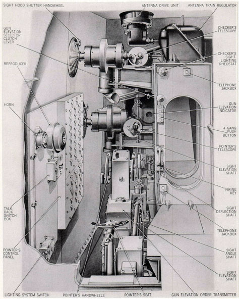
Pointer's control equipment. Figure 34 shows the controls at the pointer's station. These devices are similar to the trainer's controls, but their system arrangements differ as indicated in the paragraphs following. The manner in which they are employed in the different methods of control is explained in Chapter 2.
The pointer does not have a mechanical control selector device; instead, the control panel includes three switches that separately control the signal receiving circuit of each regulator. Each of these switches has three position selections, designated HAND, LOCAL, and AUTO, respectively.
Other elements of the pointer's control panel are three vertical columns of indicator lights that show the conditions of readiness of the power and regulator electric supply circuits. Three switches separately control the illumination supplies for these indicators. Another series of three switches are the respective master switches for starting and stopping the main
and auxiliary electric motors.
35
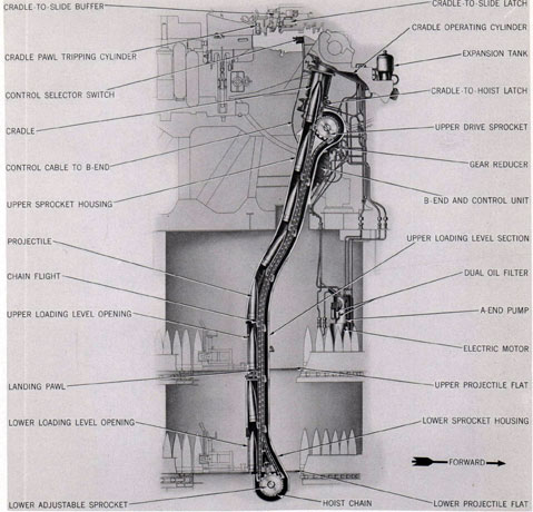
Figure 35. Projectile Hoist General Arrangement
36
Figure 36. Projectile Hoist Cutaway
The pointer's handwheels are a manual drive for electric transmitter units of an instrument, called the Gun Elevation Order Transmitter, mounted under the handwheels. This is the LOCAL control unit for signal transmission to all three gun elevation indicator-regulators.
The gun elevation indicator is a gun order follow-the-pointer dial indicating instrument for gun laying direction in LOCAL control.
Pointer's sight equipment is part of the sight assembly described on page 45.
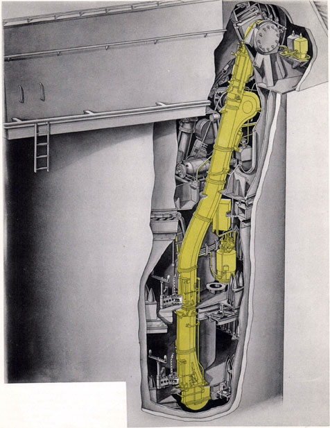
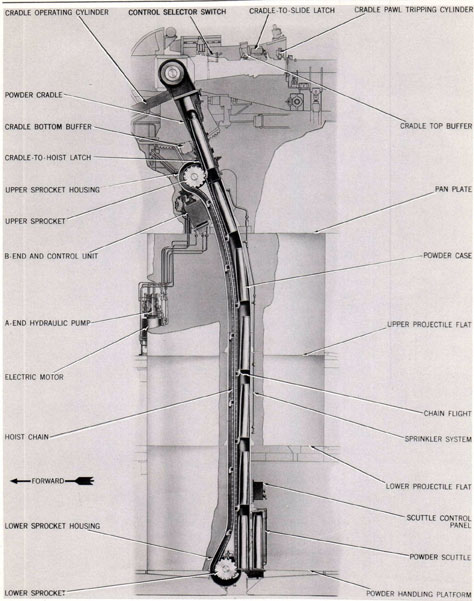
Ammunition hoist equipment
The transfer trays of each slide are separately served, automatically, with projectiles and powder cases by two ammunition hoists. These units make their deliveries without stopping the gun laying movements to bring the gun to a loading position (as required in all previous main battery installations) . The designs of the two hoists are similar, as shown in figures 35 to 38 inclusive. Each hoist consists of an endless chain conveyor, a cradle, and an electric
37
Figure 37. Powder Hoist General Arrangement
38
Figure 38. Powder Hoist
Cutaway
39
Figure 39. Projectile Ring. General Arrangement,
Upper and Lower Projectile Flats
40
hydraulic power drive. Their operating arrangements and differing details are indicated in the following brief description of each.
Projectile hoists. Each projectile hoist conveyor is a tubular unit that extends from the lower projectile flat into the gun pit at the side of its gun. It has a power-driven sprocket at the upper end and an idler sprocket at the bottom. Its endless chain has 16 flights or chain lugs for supporting projectiles. At each projectile flat, there is a loading aperture with shutter and control devices.
These loading aperture arrangements and control selecting devices enable the hoist to be simultaneously loaded on alternate ascending flights at both stowage flats, or to be loaded on every ascending flight at either flat. In either method of loading, the hoist automatically lifts its load one stage or flight distance when loading is completed, and the empty cradle is latched at the top of the hoist.
The cradle is a tubular unit suspended from a journal on the slide trunnion and arranged to swing between the top of the hoist and the side of the slide. In this oscillating movement its lower end is guided by an arc-shaped rail mounted on the gun girder. When it moves to the slide, it latches there and moves with the gun laying action. In this position it is aligned with the transfer tray when the tray is in its firing position. When it moves to the hoist, it latches so that it is held in alignment with the hoist.
The cradle has a pawl at the bottom and a large spring-ram device within. When the conveyor lifts a projectile upward, the ram is compressed and the pawl moves beneath the bottom of the projectile, thereby latching the projectile in the cradle. In this position the fuze of High-Capacity projectiles is automatically set by a remotely controlled fuze setter located in the top of the cradle.
Hoist controls. The devices which control the cycling actions of the hoist and the cradle, and which operate the latches and pawl, are hydraulic valves and an installation of switches and solenoids. It is a system comparable to the slide equipment control system, and certain of its switches are included in the interlock arrangements and controls of the gun captain's control panel.
The controls include a manually operated selector. This is a remote switch and flexible cable unit located in the gun compartment. It is a three-position function selector through which the controls are set to hoist or lower projectiles or to stop cycling action (but not to stop the power drive electric motor). The lowering control of this device has two purposes: It enables the automatic cycling action to be reversed in emergency when a misfire or casualty occurs or "cease fire" is ordered and it is necessary to unload the gun. And it enables the hoist to be employed when stowing ammunition on the handling flats.
Hoist power drive. Each hoist is separately driven by a power drive. This consists of an electric motor and A-end pump unit mounted on the upper projectile flat, and a hydraulic pipe system connecting with a B-end hydraulic motor that is coupled to a worm reducer unit that drives the upper sprocket. The cradle is operated by a double-acting hydraulic cylinder.
Powder hoist. The powder hoist is like the projectile hoist, except that its cradle is larger, its conveyor is longer, it has only one loading level, and its loading aperture is fitted with an automatic scuttle.
The scuttle is a revolving flameproof cylinder device with two compartments. It is independently driven by an electric motor which operates an oscillating crank mechanism. This mechanism rotates the cylinder 180° when the inner compartment is empty and the outer compartment has been served with a powder case.
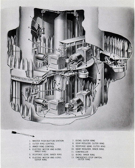
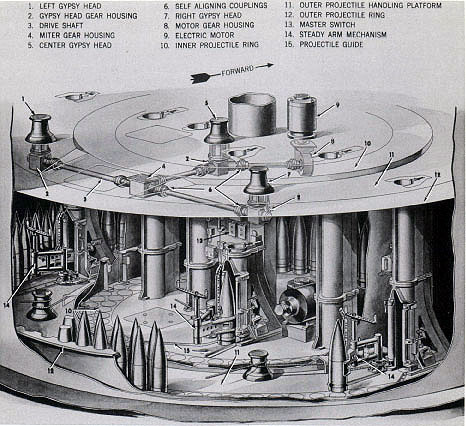
Projectile stowing and handling equipment
The two groups of equipment for stowing and handling projectiles are six power-driven assemblies installed in the projectile flats. These units are four projectile ring drives and two parbuckling mechanisms. Their arrangements are shown in figures 39 and 40 respectively.
Projectile ring drives. Each inner and outer projectile ring of each projectile flat has an attached annular rack. This rack is driven by a spur pinion through a worm gear speed reducer and an electric hydraulic power drive. The ring, the power drive, and the controls permit the
ring to be driven clockwise or counterclockwise.
41
Figure 40. Parbuckling Gear Arrangement
Upper and Lower Projectile Flats
All four power drives are alike, except for their controls. Each drive consists of a 20-horsepower electric motor, an A-end pump and control assembly, a B-end hydraulic motor and brake mechanism, and a manual control mechanism.
The A-end unit is a variable displacement pump with an automatic cycling control. This control device is a manually initiated type that operates the ring for a short arc of movement and then automatically decelerates, stops, and locks the heavy load. Inner and outer ring arcs of movement controlled by this device differ,
but each controls its ring so that the arc of movement presents six projectiles within reach of the parbuckling steady arm mechanism.
The manual control mechanisms are hand-wheels with a system of gear boxes and shafts coupled to the A-end control input. Inner and outer ring designs differ, as shown in figure 39, because of the positions of the handwheels.
Parbuckling gear assemblies. The two parbuckling gear installations are identical. Each consists of a vertically positioned 7.5-horsepower motor which drives a system of gear boxes and shafts that operates three gypsy heads. These
42
are adjacent to the loading apertures of the three projectile hoists. They run at constant speed.
A pivoted mechanism called a steady arm is also mounted adjacent to each hoist. This device is a parbuckling auxiliary that is manually controlled and power-operated by the gypsy
head snubbing rope. It operates to grab projectiles one-at-a-time from the projectile ring, and to guide and thrust them into the hoist.
Fire control equipment
The sights and gun attachments, and the control instruments listed on page 13 comprise the
Figure 41. Sights and Gun Attachments. General Arrangement
43
Figure 42. Trainer's and Sight Setter's Station. General Arrangement. Right Side
44
turret fire control installations. They are supplemented by switching and communications devices and an extensive system of wire circuits of Bureau of Ships design and cognizance.
Sights and gun attachments. Five assemblies of shafts and brackets that interconnect eleven instruments, as shown in figure 41, comprise the sights and gun attachments. These assemblies are three gun elevation attachments, a training gun attachment, and the sights. The associated instruments are: Three telescopes, a sight setter's indicator, gun elevation and train indicators, three elevation indicator-regulators, and a train receiver-regulator and a gun elevation selector.
Arrangements of this assemblage of instruments and signal transmission systems provide the following:
Manual input movements at the sight setter's indicator, made in response to synchro-received, dial-indicated orders, offset the lines-of-sight in deflection and depression from parallelism with the guns. These values simultaneously move the optics and also move input mechanisms at the regulators and elevation and train indicators. They are combined in these instruments with a third output of the sight setter's indicator, called parallax range, and with response values equivalent to turret turning movements and the elevating movements of a selected gun. These combined values are gun order correcting factors. They modify the gun orders in all methods of control by making local changes that correct the computed order for mechanical faults and that compensate for the differences in visual angles at the turret and at the controlling director.
Thus, in turret automatic control, the sight setter's indicator functions to alter the remote gun order and modify gun positions in both range and azimuth. It functions similarly in all variations of automatic control.
These correcting functions also occur when the turret is controlled locally by target sighting. In that method of control, all actions are controlled by the pointer's and trainer's station equipment.
Trainer's station. Figure 42 shows the sight arrangements at the trainer's station. The telescope at this station has common deflection
controlled by the sight setter's indicator, but the elevating movement is free under foot control by the trainer. This conventional arrangement enables the trainer to follow the target in elevation at will, as ship rolls, but compels him to operate his handwheels to turn the turret for every change in sight deflection input or change in ship course.
Pointer's station. The mechanical arrangements for moving the optics at the pointer's and checker's stations are the same values. Each instrument moves identically in response to sight setter offsets in sight deflection and sight angle. Both instruments also move identically in response to the movement of one gun.
Figure 43 shows the arrangements of the sights and of the elevation selector device at the pointer's station. It is an arrangement that operates to compel the pointer to manipulate his handwheels in order to hold his line-of sight on the target whenever the sight angle changes or the ship rolls. Thus, by reason of the offset value of the sight angle (gun order) , he is constantly holding the gun in correct range position.
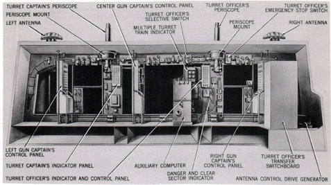
Turret officer's control equipment. Figures 44 and 45 identify the control equipment installations of the turret officer's booth. They are optical, mechanical, and electrical devices for visual observation of fall of shot, for local communication, for local solution of firing problems, and for selection of alternative methods of control.
The equipment of this booth is arranged with the ship's director system so that the turret may be operated in any one of several basic types of control and their variations. These control methods are designated: PRIMARY, SECONDARY, LOCAL, and EMERGENCY. The master selector for all is the large cabinet called the turret officer's transfer switchboard. Through this unit the turret is placed in:
PRIMARY CONTROL, so that the gun and turret drives are remotely controlled by the main directors; or,
SECONDARY CONTROL, so that the gun and turret drives are remotely controlled by directors of the secondary armament; or,
LOCAL CONTROL, so that the drives are controlled by the target sighting actions described
above; or,
45
Figure 43. Pointer's and Checker's Stations. General Arrangement Left Side View
46
Figure 44. Turret Officer's Booth. Fire Control Arrangement
Forward Bulkhead
Figure 45. Turret Officer's Booth. Fire Control Arrangement
Rear Bulkhead
47
Figure 46. Turret Fire Control Installation. General Arrangement
HI-TURRET CONTROL, so that the drives of turret I are automatically controlled by signals transmitted from turret II.
Alternatives to these switching selections are included in the transfer switchboard to permit the following variations:
In primary control, the drives may be controlled automatically, called Primary Automatic Control, or they may be remotely directed in follow-the-pointer operation, called Primary Indicating Control. Either selection can be controlled from After Plot or Forward Plot, using
48
the forward or after aloft director.
In secondary control, the turret drives may be controlled by similar automatic and indicating control variations that employ different combinations of the secondary directors and plotting rooms.
Turret local control methods include "target-sighting" control, radar control, periscope control, and combinations of these. All use the local computer for solution of external ballistics, but turret I is excluded from radar control except via turret II.
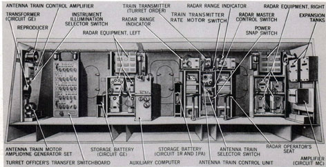
Radar control arrangements are among the feature innovations of the turret. The installations are in duplicate. They include two complete radar control sets in the booth, and two antenna train drives, antennas, and drive regulators.
This installation enables the turret crew to ascertain target direction, distance, course, and speed. It is a range-finding system that completely displaces the optical range-finder of earlier turret designs. It is a system that provides new alternative methods of local control. These enable the radar signal beam to the target to be employed as a combination line-of sight and range data factor. From derived and computed data, transmitted to the sight setter and the turret train indicator, the antenna and the sights are offset identically in azimuth, and the sights are offset in elevation. This permits two methods of drive control: automatic train drive via radar operator's turret train order with conventional pointer target sighting control, or conventional target sighting control by both pointer and trainer.
Fuze setting control. Figure 46 shows the general arrangement of all fire control units discussed above, and of the installations for automatic fuze setting and fuze setting control.
Each projectile hoist cradle includes a fuze setter. It is an automatic, power-driven and remotely controlled design that controls the fuze setting action of mechanical time fuzes. Orders received in the turret through the transfer switchboard are routed via the gun captain's control panels to amplifier cabinets located in the gun pits. These boost the power signals that operate the fuze setting motors, and their switching arrangements enable the gun captain
to stop fuze setting and set SAFE position for return to stowage.
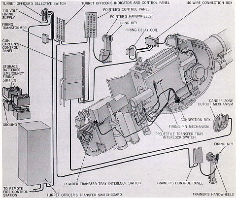
Gun firing control. The gun and powder ammunition designs provide for electrical firing only.* Powder cases do not include percussion primers, as a safety precaution, because of rough handling in automatic loading.
The electrical firing system includes other safety precautions and special arrangements. It is a selective firing control, as indicated in the diagram of figure 47, that interlocks with the gun loading and gun laying actions and permits remote or local firing. Safety features of this circuit, in addition to automatic interlock switches, include manually operated firing stop switches accessible to the turret officer, each gun captain, the pointer, and the trainer.
The automatic interlock devices consist of four switch operating mechanisms for the firing circuit of each gun. These block the firing until the transfer trays are in firing position, the breech is completely closed, and the gun is pointing into a safe firing zone. Their positions and identities are designated in figure 47. All these switches positively open the firing circuit when their mechanisms are actuated.
AUXILIARY INSTALLATIONS
Power supply equipment and circuit installations-and also all turret heating, ventilating, sprinkling, illumination, communications, and air supply systems-are auxiliaries of the turret ordnance installations. These service facilities are units of Bureau of Ships design and cognizance. Their features and general arrangements are described in the remaining pages of this chapter.
Power supply
Normal and emergency electric power is supplied to each turret from the ship's four main 450-volt, 3-phase, 60-cycle turbo generators. This power is supplied to each turret through feeder cables originating at connection boxes in the wiring trunk located below the base casting. Cables lead upward through spacer
* The gun has arrangements for attaching an accessory that permits emergency percussion fire, provided a special short-case powder charge is substituted for the normal charge.
49
blocks in the central column to a wiring recess at the top of the column, just beneath the pan floor. Slack is provided in the cables at the bottom of the column to permit twisting and flexing of the cables during turret rotation. From the wiring recess, cables are routed to a manual bus transfer panel, located on the inner wall of the inner circular bulkhead at the right rear of the upper projectile flat. (See figure 17.) This panel is equipped with switches and indicating lights for selection of either normal or emergency power supply. From the manual bus transfer panel, power is supplied to five circuit breaker power panels, consisting of: three gun equipment power panels, one for each gun; a
training gear equipment panel; and a miscellaneous equipment power panel. These circuit breaker power panels serve to supply power to all controller components of the power drives and the several auxiliary services, except the illumination system.
Illumination supply. Normal and emergency power for the illumination system is supplied to each turret from the 120-volt, 60-cycle ship's electric service system. The power is supplied to the turret by flexible cable, through the central column wiring tube, similar to the arrangements described in the preceding paragraphs. From the wiring recess at the top of the central column, the cable is routed to an automatic bus
Figure 47. Gun Firing Control System
50
Figure 48. Turret Ventilating System. General Arrangement
51
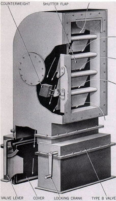
Figure 49. Ventilating System Air Exhaust Automatic
Shutter. General Arrangement
transfer panel located on the inner wall of the circular bulkhead, to the left rear of the upper projectile flat. It operates automatically to transfer 120-volt supply from normal to emergency or vice versa, when required.
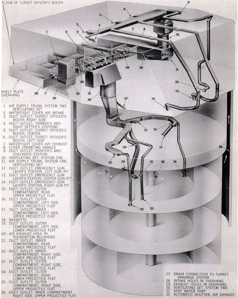
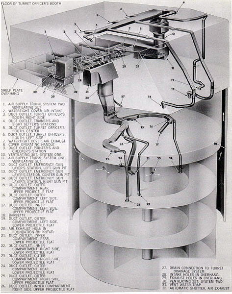
Ventilating system
Two self-contained ventilating systems supply fresh air under forced draft to all turret levels above the powder handling room. These, together with their related ducts, are illustrated in figure 48. One system consists of a 6,800-cubic-feet-per-minute electric motor-driven fan set, developing 4.2 inches total pressure. This set is vertically mounted in the
left wing sight station, before and to the left of the partial bulkhead in the position shown on figure 14.
The other system consists of a 7,000-cubic feet-per-minute electric motor-driven fan set, developing 3.3 inches total pressure. This set is vertically mounted on the inner rear circular bulkhead at the pan level, to the left of the longitudinal centerline of the turret.
System number one supplies air to the gun house and the pan level. A main duct extends across the roof of the gun house. From this main duct, three evenly spaced smaller ducts supply air to the turret officer's booth; the left and right ducts supply 1,565 cubic feet of air per minute; the center duct supplies 1,570 cubic feet of air per minute. Three additional smaller ducts extend from the main duct forward along the roof of the gun house, and down into the left, center, and right gun pits. Each supplies 500 cubic feet of air per minute. Right and left small extensions of the main duct are directed to the right and left wing sight stations, each of which supplies 300 cubic feet of air per minute to these areas.
System number two supplies air to the inner and outer compartments of the upper and lower projectile flats. Two forked, main-supply ducts extend from the fan through the plate and into the upper projectile flat. From these ducts four outlets supply 1,000 cubic feet each per minute to the inner and outer compartments of the projectile flat. Four vertically mounted extensions of the main ducts extend downward through the upper flat to just within the lower projectile flat. Two of these ducts supply 500 cubic feet of air per minute to the inner compartment; the other two supply 340 cubic feet per minute to the outer compartment.
Both systems operate to maintain slight pressure in the areas supplied. This pressure is controlled by the exhaust arrangements. Air exhaust within the gun house is controlled to maintain air pressure at one-and-one-half inches water gage. This is obtained by means of a spring- and weight-loaded automatic shutter, shown in figure 49, vertically mounted in the right wing sight station area, before the partial bulkhead. Air exhaust for both projectile levels is via screened openings cut through the upper
52
Figure 50. Turret Sprinkling System
General Arrangement
53
end of the turret circular foundation, beneath the lower roller path.
Electrical components of these ventilating sets are the motors, two controllers, and push button stations. The arrangements are similar for each set, differing only as to size and speed; motor number one is a 7.5-horsepower unit;
number two is 5-horsepower. Each is a squirrel-cage induction, two-speed, 440-volt, 60-Cycle alternating-current type. Their speeds differ, number one operating at 3,450 or 1,750 revolutions per minute, while number two operates at 1,750 or 1,175 revolutions per minute. Both motors are co-axially aligned within their
Figure 51. Turret Sprinkling System. Rotating Fireman Connection
General Arrangement
54
respective sets, and each drives a multi-bladed fan mounted on its drive shaft.
Starting, stopping, and emergency run controllers for the motors are located on a panel in the left rear of the turret officer's booth. Push buttons for both motors provide HIGH and LOW speed EMERGENCY RUN and STOP control.
Sprinkling system
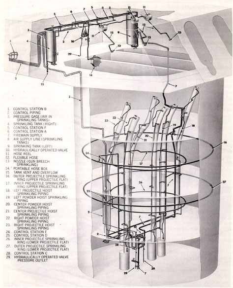
The turret sprinkling system is designed to provide a quick and efficient means of sprinkling all ammunition units in the turret-whether they be in stowage in the projectile rings, in transit via the ammunition hoists, or ready for loading at the gun breech. The arrangement permits selective or over-all control of sprinkling from both local and remote control stations within the turret, as well as from a remote control station on the exterior of the turret.
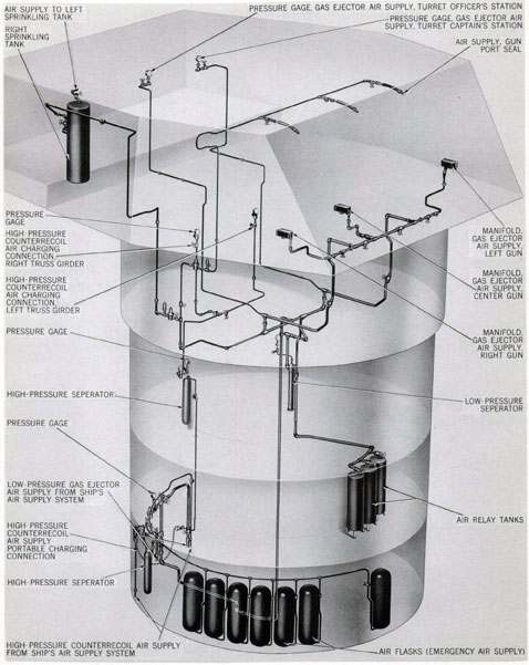
General arrangement. The system, illustrated in figure 50, includes a primary source of water supply from the ship's firemain; two sprinkling tanks for water storage within the turret; an air supply to maintain water pressure in the storage tanks; and an assortment of control and operating valves, and associated nozzles, piping, and tubing.
Rotating firemain connection. Water from the ship's firemain is led into the pit beneath the powder handling room in 2 1/2-inch copper-nickel alloy seamless tubing, secured to the deck. This tubing is then connected to the rotating fire-main connection, shown in figure 51. This connection consists of two horizontally placed sheaves or reels; one sheave rotates with the turret, the other sheave is driven by a crossed wire rope from the first sheave. Tubing from the ship's firemain is connected to piping on the second sheave by means of a swivel joint. In turn, this piping is connected to a flexible, 2 1/2-inch wire-stiffened rubber hose, which winds around both sheaves as the turret turns. The winding of the hose on the sheaves is such that when turret rotation causes the first sheave to rotate in a clockwise direction the flexible hose is wound off the second sheave onto the first, and when rotation is counterclockwise the action reverses. Working water pressure of 100 pounds per square inch is maintained throughout the full arc of turret rotation by this device.
Turret firemain tubing. Connected to the flexible hose is a 2 1/2-inch copper-nickel alloy tube, which extends vertically upward from the rotating firemain connection, adjacent to the central column, into the powder handling room. This riser is fitted with a control gate valve and a globe hose valve, both accessible in the compartment. From these valves the supply line extends to tanks at the top of the turret and to all sprinkling-head operating valves.
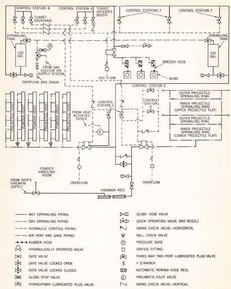
Sprinkling distribution system. The part of the system from the ship's firemain just described, is designated as wet sprinkling piping. Its extent with respect to other pipes is shown in figure 52. During normal turret operation, water is within this tubing at all times. All wet sprinkling tubing is copper-nickel alloy, seamless pipe and tubing. Fittings are flanged or socket-type, bronze, silver-brazed, and threaded bronze. Connected to this main is the dry sprinkling piping-the piping which actually leads to and sprinkles the various ammunition units. In normal turret operation, this piping contains no water. Only when the complete system, or a portion thereof, is operated does water flow through these pipes. All dry sprinkling piping is aluminum alloy seamless pipe. Fittings are threaded aluminum alloy. All dry sprinkling piping is coated, inside and out, with zinc chromate iron oxide primer or aluminum varnish.
The dry sprinkling piping for the ammunition hoists is connected to the firemain through a hydraulically operated control valve, within the powder handling room. Piping is mounted on the exterior of each hoist, and extends from the extreme lower to the extreme upper end of each hoist conveyor; there is no sprinkling device on the cradle. At spaced intervals connecting pipes lead to spray nozzles in the conveyor tube. The arrangement is such that all projectiles or powder cases within the hoists can be sprinkled.
The dry sprinkling piping for the projectiles stowed on the projectile rings is also connected to the firemain through a hydraulically operated control valve within the powder handling room. From this valve, piping leads into both the upper and lower projectile flats, forming on each flat an inner and outer sprinkling ring. Rings are constructed of 1 1/2-inch standard aluminum alloy pipe, and are mounted above and encircle
55
Figure 52. Turret Sprinkling System. Arrangement of Vent and Gage Piping, Wet and Dry Piping, and
Hydraulic Control Piping. Schematic
56
the inner and outer projectile rings of each projectile flat. One hundred fifty drilled holes, equally spaced throughout 360°, are located in each outer sprinkling ring; 74 drilled holes, equally spaced throughout 360°, are located in each inner sprinkling ring. Spacing and number of the drilled holes in the sprinkling rings is so designed that each projectile in stowage will be sprinkled.
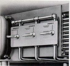
The dry sprinkling piping for the gun breeches is connected to the firemain through a control valve within the turret officer's booth. The installation consists of three spring-loaded hose reels, one for each gun, bracket-mounted to the center transverse girder, above and to the rear of each gun slide. Wound on each reel is a 12-foot long, 1/2-inch rubber hose, each hose being connected to the fixed dry sprinkling piping at the reel. From each reel, an unwound portion of the hose extends downward and is connected to a ball bearing swing joint, bracket-mounted on the respective gun slide side plate. Guarded 1/2-inch brass pipe, connected to the swing joint, is used to direct water flow through a nozzle bolted to the slide side plate. The arrangement is such that, as the gun is elevated, the hose unwinds downward from the reel; and as the gun is depressed, the spring-loaded reel winds the hose back on the reel.
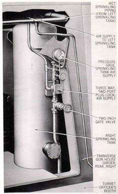
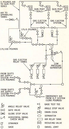
Vent and gage air piping system. A third piping system, essential to operation of the turret sprinkling system, is a vent and gage air piping system, used to maintain air pressure on the water stored in the right and left 100-gallon sprinkling tanks. A schematic of this system is shown in figure 52. Air for this purpose is obtained from the gas ejecting main air supply system. The take-off piping from the main system is fitted with a gate valve, a pressure-reducing valve, dropping the pressure from 200 pounds to 100 pounds, and a relief valve set at 105 pounds. The piping leads into the turret officer's booth and is there fitted with a swing check valve, a gate valve, and a three-way, two-port plug cock. From one port of the three-way valve, piping extends to both of the sprinkling tanks, with typical arrangements as shown in figure 53. Before entering each tank, the piping is fitted with a "locked-open" gate valve. From the second port of the three-way valve, piping leads to a tank vent and overboard
Figure 53. Turret Sprinkling System
Right Sprinkling Tank
General Arrangement
overflow, being fitted with a hose valve at this point. A 1/4-inch air-supply system leads to a system pressure gage within the turret officer's booth mounted on the partial bulkhead, right side.
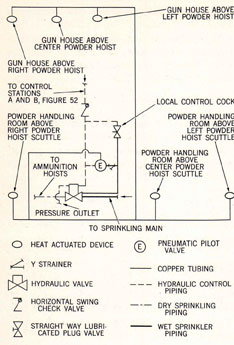
Hydraulic control piping system. The fourth piping system within the turret sprinkling system is the hydraulic control piping system, shown on the schematic diagram of figure 52. This pipe system is an arrangement of hydraulically operated valves located to control sprinkling flow in parts of the dry pipe system. None of the sprinkling control cocks is located on the firemain; rather, each functions to operate a hydraulically operated control valve, which
57
Figure 54. Turret Sprinkling System
Control Station A
General Arrangement
opens the system, permitting the flow of water from the firemain into the dry sprinkling piping. The hydraulic control piping system utilizes water in the wet sprinkling piping, under pressure, as a control fluid.
Turret sprinkling control stations. Selective control of the turret sprinkling system is provided at both local and remote control stations. These are designated alphabetically, and consist of stations A, B, C, D, E, and F.
CONTROL STATION A, shown in figure 54, is located within the turret officer's booth, right side, and has three valves on a single mounted plate on the partial bulkhead. All three valves are two-position valves, each being marked SPRINKLE and CLOSE. Valve 1 controls projectile stowage sprinkling. Turning it to SPRINKLE permits water to flow into the projectile sprinkling rings over the stowed projectiles of each projectile ring. Valve 2 controls ammunition hoist sprinkling. Turning it to SPRINKLE permits water to flow into the piping which sprays water within each of the projectile and powder hoist conveyors. Valve 3 controls gun breech sprinkling. When it is operated, it functions to send a jet of water in and around each gun breech.
CONTROL STATION B is located on the turret overhang, within a glass-faced lock box. Three two-position valves are provided at this station. These valves, in marking, operation, and function, are identical to those at control station A. (See column 1.) They differ in that they normally will be operated in emergency only, and then by personnel on the exterior of the turret.
CONTROL STATION C is located on the left side of the instrument panel, in the powder handling room. It consists of two two-position valves marked SPRINKLE and CLOSE. Valve 1 controls projectile stowage sprinkling. Operating it will sprinkle all stowed projectiles. Valve 2 controls ammunition hoist sprinkling. Operating it will sprinkle all projectiles and powder cases within the ammunition conveyors.
CONTROL STATION D is located within the lower projectile flat. It comprises a single two-position valve marked SPRINKLE and CLOSE, and is mounted on the exterior of the circular bulkhead to the right of the arch. The valve serves to operate projectile stowage sprinkling on both projectile flats.
CONTROL STATION E is located within the upper projectile flat. It is otherwise identical to control station D.
CONTROL STATIONS F. There are three F control stations. All are in the turret officer's booth, one adjacent to each gun captain's control panel. Each station comprises a single two-position valve marked SPRINKLE and CLOSE, mounted on the partial bulkhead. It controls gun breech sprinkling, any of the three valves serving to sprinkle all three gun breeches.
Air control plug cock. Adjacent to the sprinkling control station A is the turret officer's three-way air control plug cock. The cock is marked VENT and AIR SUPPLY. In filling the sprinkling tanks, before operation, the cock is set to VENT position. After water appears at the overflow, and as soon as both tanks are free of air, the cock is set to its normal AIR SUPPLY position. Should any sprinkling control cock be operated, water will be supplied from the sprinkling tanks or directly from the firemain, depending upon which is under the
58
higher pressure. Should air appear at the sprinkling nozzles, it indicates that the sprinkling tanks are empty. To continue sprinkling, it is necessary to shut off the gate valve fitted into the system just before the three-way valve, marked AIR TO SPRINKLING TANKS. This is necessary to relieve the air pressure within the system, which may build up greater pressure than firemain pressure, thus preventing filling or sprinkling. Sprinkling tanks are filled with water at all times, but air pressure is not placed on the tanks until preparing for battle condition.
Valve label plates and instruction plates. All valves are fitted with label plates, either directly on the body of the valve, when practicable, or on adjacent surfaces. Legends are black or red, depending upon the relationship of the valve to the sprinkling system; sprinkling positions are commonly red.
Two sprinkling system instruction plates, similar in design to the label plates, are located in each turret-one in the turret officer's booth, close to control station A, the other in the powder handling room. The instructions on each plate are as follows:
TURRET SPRINKLING SYSTEM
INSTRUCTIONS
TO PREPARE SYSTEM FOR OPERATION
1. OPEN FIREMAIN. CONTROL VALVE OPERATED IN POWDER HANDLING ROOM THEREBY SUPPLYING WATER TO THE ROTATING FIREMAIN CONNECTION LOCATED IN PIT. OPEN CUTOUT VALVE IN SPRINKLING SYSTEM RISER IN POWDER HANDLING ROOM.
2. OPEN VALVE IN THE 100 LB. AIR LINE TO THE AIR CONTROL COCK IN THE TURRET OFFICER'S BOOTH. ONE VALVE LABELED, "AIR TO SPRINKLING TANKS," IS LOCATED ON THE H.P. SIDE OF THE REDUCING VALVE ON PAN LEVEL, RIGHT SIDE, AND THE OTHER VALVE LABELED, "AIR TO SPRINKLING TANKS," IS LOCATED IN THE TURRET OFFICER'S BOOTH CLOSE TO THE AIR CONTROL COCK.
3. SET AIR CONTROL COCK IN TURRET OFFICER'S BOOTH TO VENT POSITION. AFTER WATER APPEARS AT OVERFLOW, KEEP COCK IN VENT POSITION UNTIL BOTH SPRINKLING TANKS ARE FREE OF AIR. THEN SET AIR CONTROL COCK TO AIR SUPPLY POSITION.
TO SPRINKLE
TURN PERTINENT SPRINKLING CONTROL BACK TO SPRINKLE POSITION. NOTE: SPRINKLING WATER WILL BE SUPPLIED FROM THE TANKS OR DIRECT FROM THE FIREMAIN DEPENDING UPON WHICH IS UNDER THE HIGHER PRESSURE. THE APPEARANCE OF AIR AT THE SPRINKLING OUTLETS INDICATES THAT THE SPRINKLING TANKS ARE EMPTY. TO CONTINUE SPRINKLING FROM THE FIREMAIN, CLOSE VALVE IN TURRET OFFICER'S BOOTH LABELED, "AIR TO SPRINKLING TANKS."
TO STOP SPRINKLING
RESET ALL SPRINKLING CONTROL COCKS TO CLOSE POSITION.
59
Figure 55. Turret Sprinkling System
Automatic Rate-of-Rise Devices
Schematic
Testing system operation. A combination flush-out and test plug assembly is provided to test the operation of the hydraulically operated control valves. The test should be performed at least once a week on all hydraulically controlled valves. To test, the cover must be removed from the bottom of the valve, and the test plug assembly screwed in all the way, until solidly engaged. With the test plug assembly installed, any one of the sprinkling control cocks controlling the valve may be turned to SPRINKLE.
Caution: Make sure that the proper control cock is operated. Should one be turned which operates another hydraulically controlled valve, sprinkling will ensue.
After opening the control cock, turn the pet cock at the bottom of the test plug assembly.
If water flows, the valve is serviceable; if not, the valve should be replaced. To complete the test, it will be necessary to reset the open sprinkling control cock to CLOSE position, then remove the test plug assembly and install the bottom cover.
Automatic rate-of-rise control devices. Heat-actuated control devices are located within the turret which automatically function to operate the turret sprinkling system in the event of fire within the turret. Six heat-actuated devices are used, as shown on figure 55. Three are located across the roof of the gun house, three feet before the transverse centerline of the turret and over the guns. Three devices are located within the powder handling room equally spaced in the powder handling area.
All six devices are connected, by means of copper tubing, 1/8 inch in outside diameter, to the top of a pneumatically released pilot valve located within the powder handling room. The valve is fitted with two ports at its lower end. To one port is connected a 1/8-inch copper-nickel alloy tube, fitted with a strainer, which extends from and is connected to the firemain. To the second port is connected a similar 3/8-inch copper-nickel alloy tube, which extends and connects to the hydraulically operated valves. The arrangement is such that, when a pneumatic pressure is exerted upon the pneumatically released valve by any one of the six heat-actuated devices, the valve opens. This permits water in the tubing from the firemain to pass through the valve, and to continue on and open the hydraulically operated control valves. Water then flows from the wet sprinkling piping into the dry sprinkling piping, and sprinkling ensues.
Each heat-actuated device is a pneumatic thermostat, or heat conductor. It is a hollow brass chamber of approximately 14 cubic inches, with no moving parts. A wire guard protects it against injury. Heat absorbed as a result of a sudden temperature rise, such as might be experienced in the case of a fire, is expanded within the chamber, developing air pressure which is conveyed by air tubing to the diaphragm of the pneumatically released pilot
valve, causing it to trip. This valve will remain open until manually closed and reset.
60
Communications
The primary circuits which provide various types of communications within each turret, between turrets, and between the turrets and other ship stations are listed below. A brief description of each circuit follows the listing. Their extent and arrangements are indicated in figures 56 and 57.
SYSTEM
CIRCUIT IDENTITY
Ready light
1R
Salvo signal
1VB
Cease-firing signal
1U
Interior communication
IC
Depression and train stop signal
DS
Intra-turret emergency alarm
RA
Train warning signal
TW
Turret announcing:-
Turret I
11MC
Turret II
12MC
Turret III
13MC
Battle telephone
JA and XJA
Supplementary sound-powered telephone
XJ
Sound-powered telephone call bell
E
Automatic telephone
J
Ready light system (circuit 1R). The ready light system comprises a turret arrangement of indicating lights, dials, and switches which indicates loading and gun laying operations being performed, and the state of readiness of the guns. Included among the components that comprise the system are the turret officer's selector switch, turret officer's indicator panel, turret officer's 6-dial and 3-dial indicators, gun captain's control panels, pointer's indicator panel, pointer's foot-operated ready switch, trainer's dial indicator, and trainer's foot-operated ready switch.
Salvo signal system (circuit 1VB). The command to fire is transmitted to turret personnel by the salvo signal system. It consists of vibrator-type horns located at appropriate positions within the turret, controlled either locally or from remote sources.
"Cease firing" signal system (circuit 1U). The command to cease firing is transmitted to turret personnel by the "cease firing" signal system. It consists of a high-intensity type bell located in the turret officer's booth, which
is rung from any of several control stations within the ship.
Depression and train stop signal system (circuit DS). Two indicator dials at each gun captain's control panel, and a 6-dial indicator for the turret officer, comprise a depression and train stop signal system which serves to indicate whenever a gun's line of fire is clear or nears the ship's structure. Indicators and lights are energized by cam-actuated switches which serve each gun in both elevation and train.
Intra-turret emergency alarm system (circuit RA). The intra-turret emergency alarm system consists of electrically operated sirens, strategically located throughout the turret, which are activated whenever serious danger exists or serious casualty has occurred. Control stations for the siren contact makers are located within the turret, on the various levels.
Train warning signal system (circuit TW). At times other than general quarters, the train warning signal system is used to warn ship's personnel on deck that the turret is about to train. It consists of a watertight warning bell, mounted on the exterior of the turret, which is energized by a snap switch within the turret officer's booth.
Turret announcing system (circuits MC). The turret announcing system permits the turret officer and the turret captain to communicate with all principal stations within the turret. A control box within the turret officer's booth provides communication with any or all stations, or a combination thereof. The system comprises an amplifier unit, reproducers, and portable microphones. Reproducers are of two types, one with a talk-back switch, and one without a talk-back switch.
Battle telephone system (circuits JA and XJA). The battle telephone system, primary and auxiliary, provides a telephonic connection between certain key personnel within the turret, and the ship's main battery plotting rooms. Push-to-talk button handsets and headsets with breastplate supported and push-button controlled transmitters are utilized.
Supplementary sound-powered telephone (circuit XJ). The supplementary sound-powered telephone system for the turret officer, comprises six local telephone circuits. Telephone
61
Figure 56. Turret General Communications Arrangements
62
Figure 57. Turret Interior Communications System. General Arrangement
63
Figure 58. Turret Illumination. General Arrangement
64
equipment used is identical in design to that used for the battle telephone system. The circuits link the turret officer with the three gun captains, and with the men at the loading apertures of the projectile and powder hoists.
Sound-powered telephone call bell system (circuit E). The sound-powered telephone call bell system comprises an audible call system which parallels most circuits of the turret officer's telephone system. It includes both high and low intensity bells, a low intensity buzzer, and associated push buttons, connection boxes, magneto, and wiring.
Automatic telephone system (circuit J). The automatic telephone circuit is a conventional, dial-type telephone system, which connects the turret, through a central switchboard, to any similar dial telephone in the ship. Two telephones are located in the turret, one in the turret officer's booth, and one in the upper projectile flat.
Illumination
Turret illumination in each turret comprises a general turret lighting system for white or low-level red illumination, and an instrument illumination system.
General turret illumination. The general turret lighting system includes lighting fixtures, switch and receptacle units, door-operated switches, hand lanterns, relays, single receptacles, distribution boxes, an automatic bus transfer panel, and associated wiring, as shown in figure 58. Normal and emergency power supply for the circuit is derived from the 120-volt, 60-cycle ship's service system through an automatic bus transfer panel located in the upper projectile flat. The bus transfer panel functions automatically to switch from normal to emergency power, or vice versa, should failure occur in either power supply.
Diffusing globe deck and bulkhead fixtures are provided for normal illumination of the gun house and pan plate. Red globe deck and bulkhead lighting fixtures are provided for battle illumination of the same areas. Diffusing globe magazine-type fixtures are provided for illumination of all turret levels below the pan plate. Combination switch and receptacle units are installed at convenient locations for operation of trouble lights and various electrically operated
portable devices. Distribution boxes with switches provide supply and individual light circuit control. Door-operated switches are fitted to the three access doors to the rear of the turret officer's booth; these are arranged to close all light circuits above the upper projectile flat when closed, and to open the same circuits when opened. A door-switch master cutout is also provided for control of the same circuits, and to serve as a master cutout for the three door-operated switches.
Instrument illumination circuit. The system that provides instrument illumination is a 6-volt circuit designated 8-inch Lighting Circuit Mk 8 Mod 0. This is a circuit that controls lamp wells and reticle lamps which illuminate indicating dials and telescope crosslines.
The circuit is arranged to be supplied from a transformer or storage battery. Its components are a transformer, storage battery, snap switch, three rheostats, branch boxes, and connection boxes, all arranged as shown in figure 59.
The transformer is a drum-shaped unit mounted in the turret officer's booth above the motor-generator amplidyne set. It steps down
65
Figure 60. Gas Ejector and Counterrecoil Air Supply Pipe System. General Arrangement
66
120-volt alternating current supply to 6-volt alternating current and delivers this current to a multiple-branch light system through separate protective fuses.
The transformer supply is controlled by a snap switch located at the radar operator's station. This switch permits alternative supply from the storage battery. It closes all branches of the lighting circuit for either source.
The principal branches supplied are three rheostats located at the trainer's, pointer's and checker's sight stations. These control crossline illumination in the respective telescopes.
Other branches supplied are the light well lamps of the computer, sight setter's indicator, and gun elevation and train indicators. These instruments and the telescopes are the essential elements of the local fire control system. The system does not extend to other equipment requiring instrument dial illumination, such as: the elevation indicator-regulators, turret officer's indicators, transfer switchboard, and radar control instruments. These are illuminated by self-contained illuminating transformer and lamp circuits.
Air supply services
Two systems of pipe lines extend through the turret to supply compressed air. These are the gas ejector supply and counterrecoil supply systems illustrated in figure 60 and described in the paragraphs below.
Gas ejector supply. Air for the gas ejector air supply is furnished by the ship's intermediate-pressure air compressors. The general arrangement of this system, together with the counterrecoil air supply replenishing pipe system, is shown in figure 60. A schematic arrangement of the gas ejector system alone, is shown in figure 61. Air is piped through the foundation bulkhead into the powder handling room in two 2-inch brass tubings. These enter on opposite sides of the powder handling room, then bend abruptly toward each other, partially encircle the fixed flat within the powder handling room, and join together to form a single air line. Stop valves are fitted to the lines before they join, and to the single line formed at the juncture. A connecting line connects the 2-inch gas ejector air supply line with the
Figure 61. Gas Ejector Air Supply System
Schematic
high-pressure air tubing entering the powder handling room. This connection is provided with a 3/8-inch by 2-inch reducing valve, reducing the high-pressure system from 3,000 pounds per square inch to 175 pounds per square inch; it also includes a relief valve set at 220 pounds per square inch. The reducing valve is automatically controlled, functioning to supply an alternate source of air from the high-pressure ship's air supply system, in the event of an emergency caused by failure of the low-pressure supply system.
67
Figure 62. Counterrecoil Air Supply System
Schematic
A single 2-inch gas ejector supply line extends vertically downward through the fixed flat within the powder handling room to the void beneath the room, then extends horizontally into the wiring truck beneath the base casting. At this point it is fitted with a swivel joint to a vertical 2-inch pipe extending upward through the exact center of the central column wiring tube. Within the wiring recess at the top of the central column, the pipe is fitted with a 90° ell, and bends horizontally forward, on the longitudinal centerline of the turret, to the exterior of the wiring recess. At this point the pipe is fitted to a 2-inch brass tube that bends downward, around the central column, to a low-pressure air-water separator, mounted at the
left side of the central column, within the upper projectile flat. Before entering the separator, the air tubing is provided with a 2-inch horizontal swing check valve and a 2-inch angle stop valve. Mounted on top of the separator is a pressure gage graduated from 0 to 400 pounds per square inch.
Tubing from the separator extends to a tee, the lower port of which is fitted with a 2-inch brass tubing extending vertically downward, adjacent to the central column, through the upper projectile flat to the lower projectile flat, and through the circular bulkhead; and is there connected to three interconnected air relay tanks mounted in the outer compartment. This line is fitted with a 2-inch gate valve just beneath the tee at the separator, and is further fitted with a 2-inch angle stop valve at the point of connection with each tank. Relay tanks each have capacity of 7.5 cubic feet.
From the upper port of the tee at the separator, 2-inch brass tubing extends upward to a horizontally mounted tubing across the upper projectile flat. Connected to this supply line are air lines which serve the gas ejectors, sprinkling system, and gun port seals.
Counterrecoil air supply. Air for replenishing the counterrecoil and accumulator air supply is furnished by the ship's high-pressure air compressors. The general arrangement of this system, together with the gas ejector air supply pipe system, is shown in figure 60. A schematic diagram of the high-pressure supply pipe system alone is shown in figure 62. This is a 3,000 pounds per square inch system. Air is piped through the foundation bulkhead into the powder handling room in two 3/8-inch copper tubings. These enter on opposite sides of the powder handling room, then bend abruptly toward each other, partially encircle the fixed flat within the powder handling room, and join together to form a single air line. A stop valve is fitted in one air line before the juncture, and a 3/8-inch bleeder-type stop valve is fitted into the single line formed at the juncture. Connections are provided between one of the air lines and a bank of air flasks mounted on the fixed flat. These have a total capacity of 165 cubic feet. Each flask is,connected to an interconnecting manifold. This manifold line is provided with a stop valve at either end to close off the
68
air flask system, and each air flask is provided with a stop valve at its point of connection, so that individual flasks may be closed from the system. An additional connection to the low-pressure gas ejector air supply system is provided with a 3/8-inch by 2-inch reducing valve, reducing the pressure for gas ejector supply purpose as previously described on page 67. The bank of air flasks is further provided with pressure gages and a 3/8-inch bleeder-type drain valve.
A portable pipe is used to connect the single high-pressure air line, on the fixed portion of the flat, to tubing mounted on the rotating portion of the powder handling room. The connection is fitted with a 3/8-inch bleeder-type stop valve, with a charging connection. From this connection, the 3/8-inch copper tubing extends vertically upward through the lower projectile flat and into the upper projectile flat, where it is connected to a high-pressure air-water separator mounted in the outer compartment of the upper projectile flat, right side, against the circular bulkhead. Before entering the separator, the tubing is fitted with a 3/8-inch high-pressure stop valve. A pressure gage, graduated from 0 to 5,000 pounds per square inch, is mounted above the separator.
From the separator, the tubing extends upward and through the circular bulkhead to a
horizontally mounted line of the upper projectile flat. Connected to this tubing, and extending upward into the right and left gun truss girders, are two tubes which provide air charging connections for portable pipes for the three guns. Each extension is fitted with a stop valve, and terminates with an air charging connection bleeder valve and pressure gage.
Hydraulic equipment filter system
In addition to the extensive airline systems described above, the turret is equipped with an elaborate system of pipes and valves that interconnects all ordnance equipment hydraulic systems. This is an installation for maintenance of hydraulic fluid. It permits clarifying the fluid without dumping the systems.
The principal unit of this arrangement is a commercial pump and filter assembly called Skinner Filter Model 3112, type HB. It is located on the powder handling flat at the position indicated on figure 21. It is permanently connected to the hydraulic system drain lines with an arrangement of valves and pipe lines. The valves enable any drive system to be drained into a sump tank, all other systems being isolated from the operation. Sump fluid can be pumped though the filter and back to the expansion tank of the power drive.