2A1. What is distillation? A ship is always surrounded by limitless quantities of water, except
when in drydock; but this is sea water, unfit for
human consumption or use in the batteries. If the
salt and other substances in sea water could be
removed there would be sufficient pure water at
hand for all purposes. Such substances can be
removed by distillation. The knowledge of distilling liquids comes from ancient days. Distillation is simply the boiling of a liquid and the condensing of its vapor back to the liquid state again.
If a teaspoon is held in a cloud of steam rising from
a teakettle, the vapor will condense on the spoon
and the resulting liquid is distilled water. In the
boiling most or all of the impurities are left behind,
so that the condensed liquid is relatively pure.
2A2. Purifying action of distillation. Salt and
other substances are dissolved, or in solution, in sea
water. Sea water does not boil at the same temperature as does fresh water (212 degrees F., at sea level
pressure), but at a temperature a few degrees
higher. When sea water boils, it is only the water
that is vaporized at this temperature, and if this
pure vapor is led into another clean container
where it may condense, the condensate is pure distilled water. The salt (sodium chloride) and
other solid ingredients in the sea water do not
vaporize and hence do not appear in the distilled
water.
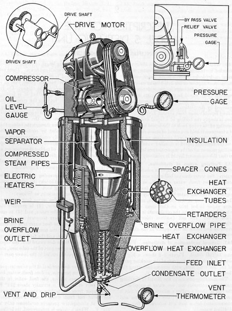
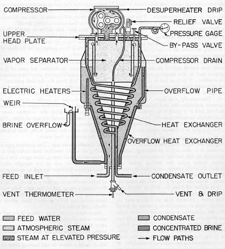
2A3. General explanation of distillation. Figure
2-1 shows a cutaway view of the Model S distilling
unit in full detail. Figure 2-2 shows a highly
simplified schematic diagram of the working parts
of the distilling unit, with arrows indicating the
flow of the water and vapor through it.
The distilling process in the Model S distilling
unit is a continuous one; sea water is supplied at
the rate of about a gallon a minute; part of this is
turned to distilled water; the solid residue and
concentrated brine flow out separately from the
distilled water.
Inside a casing, a long length of tubing is coiled
into a cone, set with its small end down. There are
ten such cones nested together. Cold sea water
enters at the bottom between the cones, that is, it
flows around the outside of the tubing. On its
way upward it is heated, so that it is boiling
when it emerges from between the cones at the
upper end. The vapor is led through a vapor separator into a compressor, where it is compressed and
is then discharged down into the inside of the
tubing. On the way down through the tubing this
vapor is gradually cooled by contact with the
colder tubing walls, finally condensing therein and
flowing out as pure distilled water to a storage
tank. The nested cones of tubing therefore act as
heat exchangers. The distilled water is technically known as distillate or condensate. The path
of this flow may be easily seen in Figure 2-2.
2A4. Necessity for compressing the vapor. The
question may be raised as to why the vapor is compressed in the distilling unit. The explanation
involves several considerations, as follows
The conical nest of tubes serves four purposes
(1) to heat the feed water, (2) to generate the
vapor, (3) to condense the vapor, and (4) to cool
the condensate to a lower temperature. In the
lower part of the nest, the feed water is at the temperature of sea water; the temperature increases
during the upward flow, and the feed water leaves
the nest boiling. On the downward flow, the vapor
is condensed in the upper part of the tube nest, and
hot condensed liquid is cooled in the lower part of
the tube nest.
Since sea water does not boil at the same temperature, for a given pressure, as does fresh water, but
at several degrees higher, the, feed water in the
upper part of the nest is actually above 212 degrees F.
The vapor from the boiling water is no longer
sea water, but fresh water vapor. Fresh water
vapor at atmospheric pressure condenses only at
212 degrees F. When a vapor is compressed, its boiling
(3)
Figure 2-1. Model S distilling unit (cutaway view).
4
Figure 2-2. Model S distilling unit (schematic view).
5
point or its condensation point is raised above the
temperature of the hot feed water in the upper
part of the tube nest. Thus, when the compressed
vapor enters the nest on its path downward, it finds
a temperature lower than its new condensation
point, and so is able to condense. This type of
apparatus accordingly is called a vapor compression distilling unit.
2A5. Heat input of the distilling unit. The compression of vapor serves still another purpose. In
the starting operation of the unit, the feed water
is raised to its boiling point by the electric heaters.
After the unit is in normal operation, there will be
a steady heat loss of definite amount through the
insulation and in the outgoing condensate and
brine overflow. This heat loss is balanced by an
input of energy from the electric motor, which is
transformed to heat by the compression of the
vapor. Theoretically, this input of heat by the
compressor maintains the heat balance at a constant level, and it is possible to operate the unit
with all electric heaters turned off. In actual practice, however, some of the heaters are usually left
on after the unit is in normal operation.
2A6. Vent to atmosphere. Since the process of
boiling the sea water takes place inside the shell
of the unit, it is necessary to prevent any increase
of pressure on the boiling water, for increased
pressure would raise the boiling point and
unbalance the whole system, and probably stop its
operation. The situation is different in the compressor. When the vapor goes into the compressor, it is sealed off from the boiling liquid and
may then be compressed without affecting the
boiling point. In order that the boiling may always take place at atmospheric pressure as found
within the submarine, a pipe called the vent leads
down from the vapor separator (Figure 2-2) out
through the bottom of the unit. This vent, being
open to the atmosphere, insures that the pressure in the vapor separator is always the same
as the pressure of the surrounding atmosphere. A
distant reading dial thermometer is connected to
the vent by a flexible tubing and gives the temperature in the vent pipe.
Although this open vent pipe leads downward
out of the unit, the steam will not flow out when
in normal amount inside, because the outer atmosphere exerts pressure upon it through the vent.
However the interior and exterior pressures are so
maintained that there is a very small excess of
pressure inside the unit, which causes a slight
feather of steam to appear at the vent. This is an
indication that the unit is operating satisfactorily.
Any excess steam which the compressor cannot
hold, however, will be able to pass out through the
vent, which thus acts as a safety device.
This vent pipe also serves to permit drainage
into the bilge of any slight amount of liquid carried into the vapor by the violent boiling action,
and prevents it from gathering on the floor of the
vapor separator.
2A7. Sea water not distilled. All the incoming
sea water cannot be distilled, for some of it must
remain as a vehicle to carry away the concentrated
salt content left from the distilled portion. The
undistilled portion, which is concentrated brine,
is maintained at a level just above the top coil of
the heat exchanger by overflow pipes. It flows
down through these overflow pipes into a separate
conical passage, called the overflow heat exchanger, located around the nest of tubes (Figure 2-2), where it gives up some of its heat by conduction through the metal walls, thus helping to
heat the incoming feed water.
2A8. Overflow weir cup. The overflow pipe after
leading out of the overflow heat exchanger at the
bottom of the unit casing, rises again for a short
distance. At the top of the upright overflow
pipe, the brine flows out through an opening called
the weir, which meters or measures the quantity
of brine overflow in gallons per hour. The overflow brine passing out of the weir falls into an
open cup and then drains down into a storage
tank called the brine receiver, from which it is
discharged to the sea.
Since water in any open vertical U-shaped container must always be at the same level in both
arms of the U, the open weir is located at such a
height as to insure that the interior overflow heat
exchanger (Figure 2-2) is always full of liquid,
which thereby exerts its full heating effect on the
sea water inside.
2A9. Time required to start sea water boiling in
the distilling unit. When starting the unit, it takes
from 60 to 90 minutes to bring the sea water to
the boiling point.
2A10. Heat balance in the distilling unit. It is
important to know the heat flow through the various
parts of the unit in actual quantities. The
following example is typical.
Heat input. The total input of heat is 16,125
Btu per hour, when the unit is fully operating
with 10,185 Btu per hour from the compressor and
5,940 Btu per hour from the electric heaters.
Heat loss. The total quantity of heat loss that
flows out through the four separate paths, is as
follows:
1,825
Btu per hour in the condensate.
11,600
Btu per hour in the overflow.
400
Btu per hour through the vent.
2,300
Btu per hour by radiation from hot
metal parts.
This represents a total heat loss of 16,125 Btu
per hour. The heat balance is not always at this
exact number of Btu per hour, because various
momentary changes of rate of feed and temperature of sea water, voltage fluctuations in the motor,
and other operating conditions, naturally will
cause it to shift around.
The heat balance of the unit is very sensitive
and all changes which may be necessary in the
operating conditions should be made slowly.
2A11. Purity of distilled water. If no leaks are
present in the system, the distilled water will contain not over four parts of salt to a million parts
of water. The distiller cannot, of course, remove
any volatile liquids, that is, liquids which boil at
or below the boiling temperature of water. For
example, in badly polluted harbors or streams, a
trace of ammonia may be present in the distilled
water; and in improperly chlorinated waters, a
trace of chlorine may likewise come over in the
distilled water.
2A12. Two-unit plant. In the complete submarine
distilling plant there are two separate units, each
with its necessary control devices, connected in
parallel. They are normally operated at the same
time, not alternately. A schematic diagram of the
complete system, with piping connections, valves,
and tanks is shown in Figure 2-3.
Two units are necessary, not only as a safety
factor, but also to provide sufficient distilled water. These units may normally be run 300 to 350
operating hours without cleaning, each giving 40
gallons per hour. This means a total of 24,000
to 28,000 gallons of distilled water. The consumption of distilled water is about 500 gallons per day
for all purposes. On a war patrol lasting 60 days,
the total consumption will be about 30,000 gallons,
and may run higher in the tropics.
2A13. Water for storage batteries. Water distilled from sea water is entirely fit for human consumption and for storage batteries. In the event
fresh water is taken aboard from shore, such fresh
water has to be distilled before it is suitable for
storage battery use. Only fresh water taken
aboard at a United States port and definitely
known to be pure may be used without distilling
or boiling for drinking, cooking, or other human
use. In distilling fresh water that may be taken
aboard, the operation of the distilling unit is practically the same as when distilling sea water; the
only difference being that the overflow is returned
to the ship's fresh water tanks from the brine tank,
instead of being discharged overboard.
2A14. Testing storage battery water. Water that
has been distilled must be tested for purity before
it is used in the storage batteries.
a. Test for purity. The instrument used to
make this test is the Kleinschmidt Water Tester,
Type No. A. It is self-contained in a bag 6 x 6 x
4 3/4 inches, operated by three flashlight cells.
A small open top container, called a cell, has
two fine platinum wire electrodes inside, which
lead through the base of the container to prongs.
When these prongs are inserted in the socket, the
electrodes become part of the electrical circuit.
The metered scale is graduated from 0 to 100
in microamperes. A reading of 40 microamperes indicates that the water contains 0.29
grains of salt per gallon. Any reading above 40
shows that the water contains too much salt for
storage battery purposes. Detailed instructions
for using the tester follow:
CAUTION. Do not touch the inside of the cell
for any reason. To do so will contaminate the
surfaces and may ruin the fine platinum electrodes
in the cell. Clean only by rinsing with the liquid
to be tested.
1. Set switch (beneath the meter) to CHECK
and turn knob (lower right) until the meter reads
50 (red line). Then turn the switch to the READ
position.
2. Remove the cell and remove the cell cover;
rinse the cell and fill it with the water to be tested.
3. Do not replace the cell cover while the cell
is full of water. The testing should be conducted
7
without the cover in place. The cell cover should
be in place only when the cell is empty and not in
use.
4. Wipe moisture from the outside of the cell,
particularly the prongs in the base, with a clean
cloth. Care should be taken to prevent the cloth
or anything else from coming in contact with the
water in the cell being tested.
5. Insert the cell in the socket carefully so as
not to spill any water, and read the meter immediately. Do not wait for the meter needle to steady
since it may drift either up or down from the
correct initial reading.
6. The Model S distilling unit, when working
properly, will produce water having a reading
between 10 and 20. Water giving readings less
than 40 is suitable for use in storage batteries;
however, readings as high as 40 indicate that leakage is occurring within the still.
7. If a reading is obtained which indicates contaminated water, this should not be taken as the
final test. Five or six check tests should be run
to make sure the water itself and not the tester is
faulty.
8. The tester serves to protect the batteries
against an excess of sodium chloride and thereby
serves to indicate whether the distillate is being
contaminated by sea water. It will not protect
against an excess of iron, copper, or nickel. Samples of battery water should be given a complete
chemical analysis to determine conformity to the
Bureau of Ships instructions when shore testing
facilities are available.
9. The tester is shipped from the factory without the flashlight cells necessary for its operation.
Three Navy Type O flashlight cells should be installed for operation. If the tester is to be stored
for any length of time, especially in tropical
climates, the flashlight cells should be removed
from the tester.
10. When check readings cannot be adjusted to
50, the flashlight cells should be renewed.
b. Silver nitrate test. Silver nitrate is sometimes used as a quick test of the condensate. Pour
some of the condensate in a glass. Drop in a few
drops of silver nitrate solution or a small crystal
of silver nitrate. If the water remains perfectly
clear, it is safe for storage battery use. If any
cloudiness or precipitate shows, the water is not
fit for storage battery use.