3A1. Main parts. The Model S distilling unit
consists of eight main elements: insulation, shell,
heat exchanger, vapor separator, over/low heat
exchanger, compressor, motor, and variable pitch
drive.
3A2. Insulation. Because of the delicate heat balance on which the unit operates, the insulation
must be very efficient, so that as much of the heat
as possible may be retained inside the unit to do
its proper work.
The whole apparatus, with the exception of the
motor and variable pitch drive, is covered with a
2-inch layer of glass wool insulation. This insulation is attached to stainless steel jackets, which
form the outer casing of the unit. The jackets
with insulation are held in place by clamps and
are readily removable.
3A3. Shell. Inside the jacket and insulation is
the shell, against which the insulation makes contact. This copper nickel shell encloses only the
heat exchanger and vapor separator. It consists
of two parts, the cylindrical upper part and the
conical lower part; the two parts are bolted together. The upper shell is bolted to the upper
head plate, which is the main support of the whole
unit. The lower part of the shell consists of two
nested conical sections 1/16-inch apart, bolted at the
bottom to the lower head plate. The space between these two lower conical sections forms the
overflow heat exchanger (Figure 2-2).
3A4. Heat exchanger. Within the lower conical
portion of the shell lies the main heat exchanger,
projecting part way up into the upper cylindrical
portion. The heat exchanger consists of ten cones
of copper nickel tubing, nested together and
pointed downward. Each cone is made up of
eight lengths of 1/4-inch o.d. copper-nickel tubing.
Each piece of tubing is 44 inches long. The tubes
are wound very tightly against each other in parallel on a cone shaped mandrel. They are tack-brazed
to prevent their unwinding. The cones
measure about 4 inches in diameter at the bottom,
19 inches in diameter at the top, and are a little
over 2 feet high. The upper ends of the tubes are
connected by unions to eight upper headers placed
vertically, and attached to the upper head plate.
The lower ends of the tubes in each cone are brazed
to a small coil header, horizontally placed, connected by unions to a single lower discharge
header.
3A5. Retarders. A 1/8-inch square metal rod is
inserted into the lower two-thirds portion of each
tube. These rods are called retarders, and serve
to decrease the inner area of the tubes through this
section so that most of the condensate comes in
contact with the walls of the tubes, thereby obtaining maximum heat transfer. The retarders also
limit the flow of steam through the tubes, thus
maintaining proper compressor discharge pressure
(see Figure 2-1).
3A6. Nesting of coils. Five of the ten cones of
tubing are wound right hand and five left hand.
They are alternated in the assembly.
Between the cones of tubes there are assembled
three sheet metal cone spacers made of copper
nickel, .020 inch thick. These metal spacers are
inserted to form a seal between the cones of tubing.
Three are used to provide sufficient flexibility to
form a contour to fit the tube cones tightly. If
only one spacer were used it would have to be of
such thickness that it would require machining to
make a tight seal. These spacer cones, acting as
seals, insure that the feed water travels around
the small passages that exist between the tubes and
the spacer cones (Figure 2-1). Having the cone
shaped coils wound both left and right and installed alternately prevents their interlocking
when forced tightly together. Inside the inner
cone of tubes there is another sheet metal cone,
the inside of which is sealed off and has no working
(9)
purpose. The upper plate of this cone is the
floor of the vapor separator. The vent pipe passes
out through the bottom of this cone.
3A7. Feed water flow. The incoming water enters from the single feed inlet pipe to the triangular spacers between the tubing and spacers and
flows up through a path about 30 feet long before
it emerges at the top. During this flow, heat
transfer takes place by conduction through the
walls of the tubing, (a) heating the feed water
gradually to boiling, (b) vaporizing two-thirds of
it, (c) condensing the vapor from the compressor,
and (d) cooling the condensed liquid.
3A8. Electric heaters. The heat exchanger projects part way up into the upper cylindrical portion of the shell. Here, between the cones of tubes
and the shell, is a narrow space into which the
water, now at the boiling point, enters (Figure
2-2). The eight electric heaters, spaced equally
around the shell, extend into this space. The
water level is maintained above the tops of these
heaters.
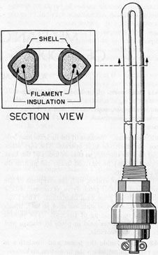
The heaters are 500 watts, 125 volts special
chromalox immersion type, of hairpin design
(Figure 3-1). They measure 17 5/8 inches over-all
in length; 14 inches immersion length; 12 5/8 inches
active heating length. Two heaters are wired
in series to each switch, requiring four heater
switches. Replacement heaters are carried in the
spare parts box, with a special wrench for removing and installing them.
CAUTION. The electric heaters should be
turned on only when submerged as they will burn
out unless covered with water. The large quantity
of heat produced is safely carried away by the
surrounding water.
3A9. The vapor separator. The vapor separator
is enclosed by an open cylinder extending downward from the upper head plate. This cylinder
is concentric and inside another open end cylinder
extending upward from the conical shaped filler
for the heat exchanger. The floor of the separator
is formed by the bottom of the outer cylinder and
lies about 4 1/2 inches below the topmost coil of the
heat exchanger. The vapor separator is thus a
separate enclosed chamber. The vapor from the
boiling water rises in the narrow space between
the shell and the outer separator wall; it then descends between the walls, and enters the separator
Figure 3-1. Electric heater.
chamber. This circuitous passage of the vapor
causes any mist of liquid that may be carried up
by the vigorous boiling action to separate from
the vapor; hence the name-separator. Such liquid will of course not be distilled, and must be
prevented from entering the vapor compressor or
it will contaminate the distilled water. The separated liquid collects on the separator floor and
drains out through the vent pipe.
3A10. Vapor baffle. On entering the separator,
the vapor first strikes against a baffle. This baffle,
cylindrical in shape, is attached at the top to the
upper head plates. It extends to 1 inch above the
separator floor and is located 1 inch inside the
outer separator wall. This arrangement insures
that the vapor, after passing through the narrow
inlet opening at the top, passes down and through
the free end of the baffle and into the separator
chamber.
10
3A11. Vent pipe. The vent pipe is a 1/2-inch pipe
extending from the hole in the middle of the separator floor to which it is connected, down through
the center axis of the unit and out. The external
end is open to the atmosphere.
3A12. Water level. The water level in the unit is
maintained at about 1/2 inch above the topmost
coil of the heat exchanger by means of two overflow pipes, diametrically opposite each other. Figure 2-2, being a schematic view, shows only one
of the overflow pipes.
3A13. Overflow pipes. These two pipes, called
low overflow pipes, carry the undistilled and concentrated brine down through the overflow heat
exchanger. For safety purposes a second pair of
high overflow pipes is placed between the regular
short overflow pipes; they too drain into the overflow heat exchanger.
3A14. Vent damper. The vent damper is a device connected to the vent pipe of the unit in order
to damp out wide and sudden fluctuations of air
pressure. Such fluctuations occur on occasion in
certain types of submarines when a torpedo is fired
or during a quick dive, or under other conditions.
The distilling unit is sensitive to changes of air
pressure because the surface of the boiling water
is open to the atmosphere inside the submarine
through the vent. With rapid changes of pressure, the unit will stop operating since the penetration of the air through the vent, reaching the
space where the water is boiling, will cause a sudden increase of compressor pressure. This difficulty is overcome by installing the dampening
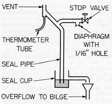
device on the vent pipe. A functional diagram of
this device is shown in Figure 3-2.
The vent damper is a Y-shaped piping arrangement connected into the vent. One upper branch
of the Y is open to the air through a 1/16-inch hole
in a diaphragm. The small size of this hole causes
any wide and sudden changes in hull pressure to
be communicated very gradually to the surface of
the boiling water in the unit. A stop valve is
placed at the end of this branch for a good supply
of air at starting. This valve should be opened
Figure 3-2. Vent damper.
wide when starting the unit, and should be shut
after the unit is operating.
The lower branch of the Y leads down into an
open top seal cup which is about 4 inches in diameter and 5 inches high. This cup should be filled
with water to the level of the overflow connection
before starting the unit.
The action of the dampening device is as follows: If the air pressure in the hull decreases,
there will be a small discharge of steam into the
water in the seal cup with no other apparent
changes. If the air pressure in the hull rises, the
increased pressure on the water in the open seal
cup will force some water up the seal pipe, to
balance the difference in pressure between the unit
and the hull. Air will gradually pass into the
unit through the diaphragm 1/16-inch hole and
equalize the pressure at such a rate that the unit
will have time to adjust itself to the changed conditions without stopping.
The unit will operate normally during this adjustment period and the only difference noticeable
will bean increase in pressure of the compressor.
The pressure will gradually drop back to normal.
Any liquid running from the vent will pass out
of the seal pipe and overflow into the funnel, as
it would without the attachment, under all pressure conditions in the submarine.
B. THE TWO-LOBED ROOTS-CONNERSVILLE COMPRESSOR
3B1. Impellers. The vapor is compressed by the
rotating action of the two double-lobed impellers,
each a one-piece bronze casting, accurately machined. They are, in effect, a pair of two-tooth
11
338450 0-55-2
gears of involute form. The drive is by belt from
a motor mounted above the compressor case to a
pulley on the shaft of one impeller. Opposite to
the drive end, a pair of one-to-one precision gears
turns the other impeller. Reference to the circular inset view in Figure 2-1 shows this construction
clearly. Figure 5-1 shows an exploded view of the
two-lobed compressor.
3B2. Impeller gears. The impeller gears run in
an oil bath contained in an oiltight housing. The
shafts pass out through packing glands. An oil
level indicator is provided on the gear housing.
See also Section 5B1.
3B3. Impeller housing. The impellers are enclosed in their own housing which has semicircular
ends (Figure 2-2). The vapor enters from the
vapor separator, passes through channels to the
top of the compressor, is carried around between
the impellers and the casing, and is discharged as
compressed vapor to the heat exchanger.
3B4. Impellers not lubricated. There is no contact either between the impellers or between the
impellers and the impeller housing. There is
a slight clearance of a few thousandths of an inch
around all faces of the impellers. Therefore no
lubrication is needed inside this housing.
3B5. Slip. Since there is higher pressure on the
discharge side than on the inlet or suction side,
there is a backward slippage of the vapor. This
slippage is slight, and reduces the compression
only by a very small amount.
3B6. Compressing action. As the impellers rotate in opposite directions, each in turn alternately
cuts off a pocket of vapor when it reaches a vertical
position, as is shown for the left impeller in Figure 2-2. When this impeller reaches the position
where that pocket of vapor may escape, the impeller lobes, continuing to rotate, squeeze or com
press the vapor. This type of compressor is very
efficient. The fact that no oil is needed inside the
compressor housing insures that no oil can get into
the distilled water.
3B7. Compressor motor. A 7 1/2-hp motor with
necessary starting and protective electrical equipment
is bolted on top of the compressor casing.
The drive to the compressor shaft pulley is by
four texrope V-belts.
3B8. Variable pitch drive. The drive pulley on
the motor is of the adjustable or variable pitch
type. The amount of variation of pitch is small,
5.400 to 6.600 inches' pitch diameter of the pulley,
and is intended only to adjust the tension of the
belts. The four left-hand sides of the pulley
grooves are attached to a sliding sleeve. Rotating
this sleeve moves the left-hand sides toward or
away from the four stationary right-hand sides.
Since the belt grooves are V-shaped in section, this
motion increases or decreases the pitch diameter.
Adjusting the variable pitch drive. Loosen the
setscrews on the sleeve. Turn the adjustable part
of the pulley with the special spanner wrench
found in the spare parts box until the belts are at
proper tension. The proper tension is that which
gives the belts, when running, a bow of about 1
inch on the slack side. Then tighten the setscrews.
3B9. Upper head plate. This heavy copper nickel
plate is 13/16 inch thick. It is the main support of
the distiller, and is fastened securely to brackets
which are bolted to a bulkhead. To it is bolted the
shell of the unit. In the bottom of the head plate,
inside the shell, is fastened a casing of 3/16-inch
thick copper-nickel, forming a separate compartment 3/4 inch high and of nearly the same diameter as the shell.
Four short 1 3/4-inch o.d. tubes are set into the
head plate and direct the vapor from the separator
to the compressor, without permitting it to enter
the head plate compartment (see Figure 2-2).
After the vapor is compressed, it is discharged
from the compressor down through a 3-inch hole
into the upper head plate compartment. The
vapor leaves this head plate compartment, or discharge vapor space, at the sides through eight
1-inch o.d. pipes called upper headers, which lead
down to the heat exchanger tubes.
NOTE. The Roots-Connersville two-lobe compressor has been replaced on most submarines by
the General Motors three-lobe compressor. This
compressor is described in Section 7B.
C. CONTROL DEVICES
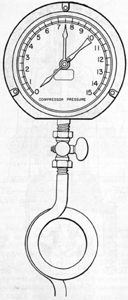
3C1. Pressure gage. A 0- to 15-psi pressure gage
(Figure 3-3) is connected into the discharge vapor
space of the upper head plate, which, for operating control, provides continuous reading of the
12
Figure 3-3. Pressure gage.
pressure of the vapor going into the heat exchanger.
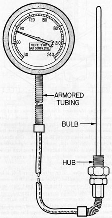
3C2. Vent thermometer. A distant reading dial
thermometer indicates the temperature in the vent
pipe. The bulb of the thermometer (Figure 3-4),
inserted in the vent pipe, is connected by a 9-foot
armored capillary tubing to the dial which is graduated from 30 degrees F. to 240 degrees F.
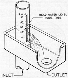
3C3. Weir. The weir (Figure 3-5) measures the
rate of flow of the overflow brine discharge. The
overflow pipe leads out at the bottom of the unit,
then turns vertically upward along the side to such
a height that the interior overflow heat exchanger
is always full of liquid. The top of the pipe is
open, and also very near the top is an open vertical
slot 3 inches long and 1/16 inch wide. This slot is
the weir, through which the liquid flows. The
weir has a scale alongside it, and the height of
the liquid pouring through the weir indicates the
rate of flow in gallons per hour (gph), the maximum reading being 50 gph.
Just below the weir slot is a cup, 3 1/4 x 6 x 2
inches high, surrounding the weir pipe and silver
Figure 3-4. Vent thermometer.
13
brazed to it, into which the liquid falls. From
the bottom of the cup the brine flows through a
drain pipe, to a temporary brine receiver tank,
and finally to the sea.
Care of the weir. The weir slot must be kept
clean and free of any deposit at all times, otherwise the readings will be in error.
Figure 3-5. Weir.
Reading the weir. The liquid flows out of the
slot and down into the cup in a curve. Care
should be taken in reading the scale not to sight
this outside curving part of the flow against the
scale, or the reading will be too low. One should
sight through the slot, reading the highest level
of the liquid inside the weir against the scale.
With sea water feed, there should always be a
minimum of 20 gph flowing.
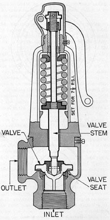
3C4. Relief valve. This valve (Figure 3-6) is located on the upper head plate adjacent to the compressor. It connects through the head plate into
the compressor discharge space, to prevent overloading of the compressor motor. The valve is
normally closed under spring pressure set at 7 1/2
psi. It can also be manually opened at any time
by lifting the lever. It is a safety valve, not a
control valve.
Figure 3-6. Relief valve.
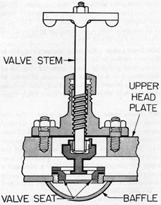
3C5. Bypass valve. The bypass valve (Figure
3-7) is not a separate valve, nor connected into
the system as ordinary valves are. It is, instead,
an integral part of the upper head plate. The
bypass valve opening connects the compressor discharge space and the vapor chamber above the
boiling sea water (Figure 2-1). The round part
at the bottom is a bale and is open at both ends
(Figure 3-7). The bypass valve is normally
closed during distillation, but it is temporarily
opened at starting, as described in Section 4B1.
14
Figure 3-7. Bypass valve.
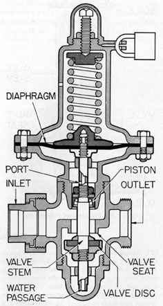
3C6. Pressure reducing valve. The pressure reducing valve (Figure 3-8) is connected into the
sea water feed line between the feed pump and
the feed water strainers. The incoming pressure
through the pump may vary from 35 to 150 psi.
This reducing valve measures 9 3/4 inches in
height. There are two separate airtight compartments in the valve, divided by a rubber diaphragm.
In the upper compartment is a spring, which may
be set to provide a given reduced pressure by
means of the adjusting screw. The cover cap
over the adjusting screw is secured by a padlock
to prevent tampering.
The lower compartment is further divided into
two separate spaces by a small piston attached
to the middle of the stem, the piston sliding in a
cylinder (Figure 3-8). The stem has whole drilled
through from its lower end to just above the piston, where a port leads out into the space above
the piston. Figure 3-8 shows how the feed water
bears both upward against the piston and downward against the valve disk, thus balancing. The
water in the outlet side of the valve also flows up
through the stem and bears against the diaphragm,
keeping the spring in balance at its set pressure.
The total resultant pressure of these opposing
forces is the desired reduced pressure asset by
the spring. The piston-and-stem arrangement
further tends to damp out vibrations caused by
pressure surges of the feed water.
Figure 3-8. Pressure reducing valve.
3C7. Flow control valve. A flow control valve
(Figure 3-9) is installed in each feed line going
to the two units. This valve, sometimes called a
feed valve, is a conventional globe valve, installed
just after the feed water strainers. A scale alongside the handle stem indicates the number of
turns which have been given, and a dial on the
15
Figure 3-9. Flow control or feed valve.
stem shows the amount of any one turn. Thus
any position of the valve may be precisely read,
and exactly repeated at a later time. The valve
is so designed that equal openings give equal increases in the rate of flow.
3C8. Feed pump. The main sea water supply to
the unit is fed in by a centrifugal type motor-driven feed pump, bulkhead mounted, capable of
delivering 3 to 4 gallons per minute of water at
30 psi gage pressure. The feed may also be from
auxiliary salt water supply, or from fresh water
supply.
3C9. Water tanks. a. Distilled water. The distilled water, from both units, flows into a distilled
water receiver or tank (Figure 2-3), made of nonferrous metal, of approximately 46 gallons capacity. Air at 10 psi is admitted at the top of the
tank to give a head pressure. A petcock is provided for sampling. There is also a vent and a
drain to the bilge. Piping connections lead to the
desuperheater tank, to the battery water tanks, and
to the ship's tanks.
b. Brine receiver. The overflow of concentrated brine flows from the weirs to a brine receiver or tank, made of copper nickel, of approximately 23 gallons capacity. Air at 30 psi is
admitted at the top of the tank to provide a head
when discharging overboard. There is a vent
and a drain to the bilge. The drain to the bilge
has a side-swing connection leading either overboard or to fresh water storage when feeding
fresh water.
D. THE DESUPERHEATER
3D1. Desuperheater. An 8-gallon desuperheater
tank, fed by a pipe from the distilled water tank
(Figure 2-3), is supported above the units. A
water level gage is attached to the desuperheater
tank, and an overflow pipe leads to the bilge.
From the bottom of the desuperheater tank, a
1/4-inch tube leads to each of the compressors and
into the impeller housings above the impellers.
Valves in these tubes are adjusted to cause the
distilled water to flow as drops, not its a steady
stream on the impeller lobes. Since the drip is
inside the compressors and hence not visible, a
sight feed glass is inserted in each tube just outside the compressor with a glass window through
which the water drops may be seen to pass. In
normal operation of the units the desuperheater
flow is at a rate of 200 drops or more per minute.
This is a very rapid flow and is the rate that exists
just before the flow becomes a steady stream in
the sight glass.
3D2. Need for desuperheater. When steam generated by boiling liquid at atmospheric pressure
and a temperature of 212 degrees F. is compressed mechanically to a pressure between 3 to 6 psi, the
steam is superheated and reaches a temperature
of 285 degrees to 400 degrees F. in the compressor. If this compression is carried on in the presence of water, the
water removes the superheat from the steam and
allows it to pass into the distiller at a temperature
of saturated steam, which is 222 degrees F. at 3 psi and
16
230 degrees F. at 6 psi gage. Desuperheating is needed
for two purposes
a. Water from the desuperheater tank dripping
on the impellers keeps the impellers and their
shafts cooled. This cooling action prevents too
great an expansion of the impellers by heat, thus
retaining the required clearance of the impellers.
It also prevents the shaft packing from getting
too hot, which would cause rapid deterioration of
the packing.
b. Better heat transfer is obtained from saturated steam than from superheated steam. A
rapid rate of heat transfer is necessary to assist
in keeping the feed water boiling; the quicker the
steam condenses, the lower the pressure on the
discharge side of the compressor will be.
Distilled water must be used for this desuperheating process. Ordinary fresh water contains
various minerals and chemical compounds. These
substances, while harmless to human beings, would
be deposited on the impellers (since only the water
vaporizes) and would gradually build up to a
thickness that would cause the impellers to bind.