RAK SERIES RADIO RECEIVING EQUIPMENTS
Use.-Ship-shore, CW, MCW and voice. * Frequency range.-15 to 600 kc. in six bands. Power required for operation.-Direct current.-6 volts, 2 amperes;
180 volts, 45 milliamperes.
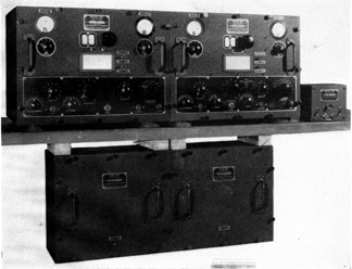
Description.-The RAK series of radio receiving equipments are used as communication receivers on CW, MCW, and voice. The RAK, and the associate receiver RAL, are often used together to cover a still wider range and for such purpose may be used with the control unit to permit reception with either receiver or both receivers simultaneously, by one operator. Beginning with RAK-6 changes are made to eliminate radar interference, and additional changes are made in the RAK-7, RAK-8 such as the concentric plug and jack for the antenna to better shield against interference. The circuit employed consists of two stages of TRF, one regenerative detector, low pass filter, first AF and audio output connected to a tube sometimes referred to as an AVC but more properly called a limiter. The set is designed for operation with 250 volts "B" and 6.3 volts "A" supply; however, some economy of operation can be obtained with satisfactory operation by use of 150 volts and 6 volts from batteries. The power unit is very carefully designed in order to maintain an accurate calibration of the receiver unit and a high degree of frequency stability. The power supply circuit includes RF filters on the a-c supply line, a current regulating ballast lamp, an electrostatically shielded power transformer, rectifier tube, two-stage filter, voltage regulator, and a protective bleeder. The set may be operated without the ballast lamp but at a sacrifice of voltage regulation. Provision is made for rubber type mounting of the receiver and all component units may be bolted in place. The unit is completely shielded both internally and externally to minimize cross talk between receivers. All power leads are filtered with resistance capacity filters. Inter stage shielding is provided to increase selectivity and stability, and to minimize reaction. The audio system includes two stages of amplification and an output limiter. Filters are provided which increase the effective CW selectivity and improve the signal to noise ratio. A low-pass filter immediately follows the detector circuit and may be disconnected from the circuit by means of a switch on the front panel. A variable attenuator, which may be switched in or out of the circuit by means of a panel control, follows the low-pass filter. A choice of resonant frequency is obtained by the use of a 10-position switch and a 2-position range switch. An audio limiter tube is cut in or out of the circuit by a panel switch and its effect is in turn controlled by an adjustable potentiometer located on the panel which determines the bias on the limiter tube. A rectifier type DB output meter and range switch are provided on the front panel. The meter indicates the audio level delivered to the headphones. A voltmeter which indicates filament voltage is provided on the front panel. Unicontrol is accomplished by means of a three-gang variable capacitor tuning the two RF stages and the detector. A switch on the receiver controls power when supplied by a battery. A switch on the power supply controls power when A. C. is used and the panel switch is inoperative. When the control unit is used the switches in it control power to either set and the panel switch and power supply switches are inoperative. The control unit combines the output of the two receivers. A three-position switch makes available in two headphone jacks, signals from either or both of the receivers. The 115-volt supply feeds through fuses into the control unit and supply cables connect to each receiver. To permit greater ease in searching and following drifting signals, a very small trimmer capacitor (frequency vernier) controllable from the front panel has been provided. This adjustment makes possible the variation of the autodyne oscillator frequency by an amount between 0.35 and 0.5 percent of its frequency. The greater range of adjustment is obtained at the high frequency end of the various bands. In order to obtain optimum performance of the equipment under all service conditions, small trimmer capacitors adjustable from the front panel are provided on the first and second RF tuned circuits. The antenna is inductively coupled to the first tuned circuit for maximum energy transfer and the best possible signal to noise ratio. When it may be necessary to operate both RAK and RAL receivers on a common antenna, a lower coupling is desirable. The binding posts have, therefore, been so arranged that a capacitor is placed in series with the antenna coupling coil when connection is made to the "common" binding post. No receivers other than one Model RAL or one Model RAK should be used on the same antenna except as an emergency measure. When RAK and RAL receivers are connected to one antenna, the "common" connection should be grounded through a one-half megohm static drain. TECHNICAL FEATURES Tube complement | Number |Old type | New type Function | of tubes | No. | No. POWER UNIT Rectifier | 1 | 38180 | 80 | 1 | 38593 | 5Z3 # Voltage regulator | 1 | 38274 | 874 Current regulator | 1 | | (ballast tube) | 1 | 35276 | 876 receiver UNIT | 1 | | First RF amplifier | 1 | 38646 | 6D6 Second RF amplifier | 1 | 38646 | 6D6 Detector | 1 | 38646 | 6D6 Output limiter | 1 | 38041 | 41 Audio output | 1 | 38041 | 41 First audio | 1 | 38646 | 6D6 Total 9 # On later model RAK-4 and on.Type of receiver.-Tuned RF with limiter on the audio output. Type of reception.-Pure, modulated, or interrupted CW; damped radio signals or voice. ** Input.-Single line antenna, inductively coupled to the first tuned circuit. Output impedance.-600 ohms. Power output.-Adustable, 170 milliwatts. Sensitivity.-2 to 5 microvolts for 6 mw. output. Antenna.-50 feet in the clear as high as possible, grounded. Radiation frequencies.-Safe all frequencies. Band coverage: Band: Frequency rang in kc. 1 15 to 25 2 25 to 43.5 3 43.5 to 77.5 4 77.5 to 153 5 153 to 308 6 308 to 600Weights, dimensions, and Navy type numbers: Unit | Navy type | Height | Width | Depth | Weight | | Inches | Inches | Inches | Pounds Receiver | # CRV-46155 | 13 5/16 | 15 | 16 3/32 | 74 Power | CRV-20131 | 12 1/4 | 14 | 8 5/8 | 41 Control | CRV-23073 | 4 3/4 | 5 3/8 | 3 5/8 | 2 # CRV 46044 from RAK to RAK-5.* Not recommended for voice as the selectivity is so sharp that considerable distortion results. ** Not recommended for voice on account of the selectivity. REFERENCES:The information enclosed here is excerpted from:Catalogue of Naval Electronic Equipment-April 1946- NavShips 900,116.
|