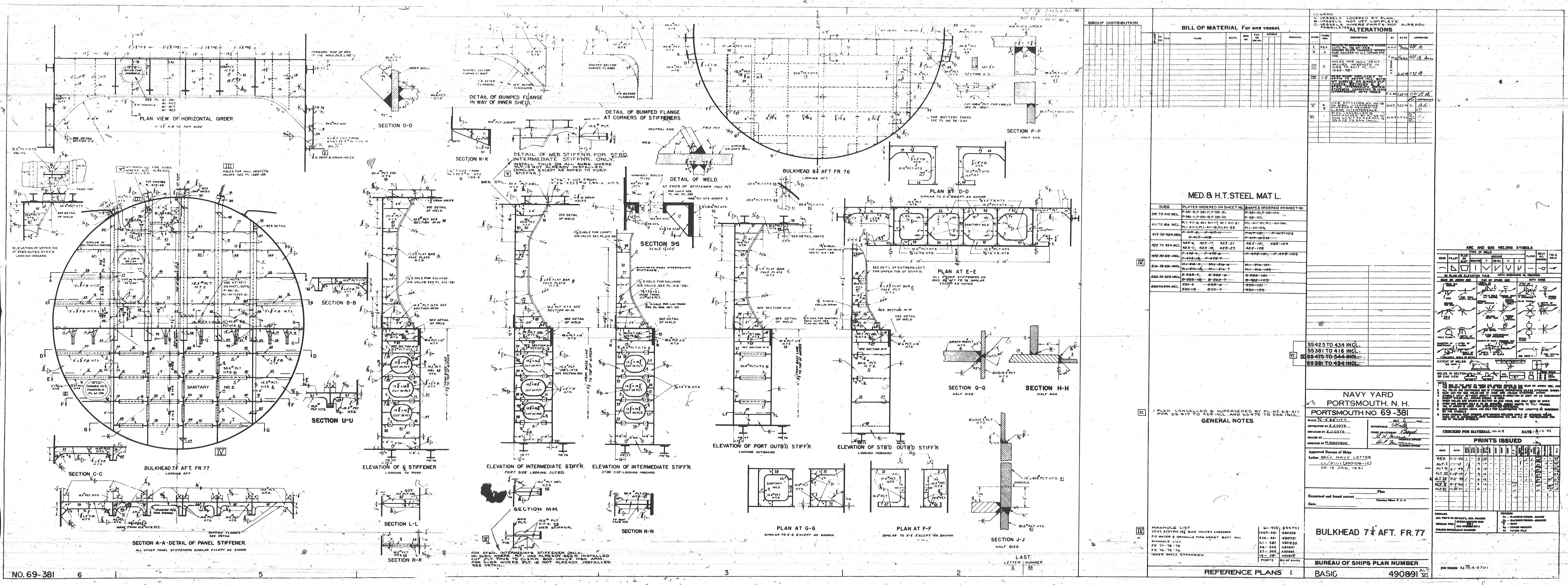
I added all the relevant drawings that I have found so far up on: https://maritime.org/tech/drawings/index.htm Includes: https://maritime.org/tech/drawings/check-valve-2inch_ss172-s41-0287_5400-07-0222.jpg https://maritime.org/tech/drawings/fresh-water-special-fittings_basic491073alt4_5400-06-0099.jpg https://maritime.org/tech/drawings/fresh-water-and-plumbing-systems-diagram_ss383-s4804-68152_ATNARA.jpg https://maritime.org/tech/drawings/fresh-water_basic491057alt4_5400-06-0068.jpg https://maritime.org/tech/drawings/fresh-water-crews-quarters-and-aft-bat_s383-s4804-68739_5400-11-0134.jpg https://maritime.org/tech/drawings/fresh-water-mess-galley_basic49107x_5400-06-0101.jpg https://maritime.org/tech/drawings/bulkhead-7dot25inch-aft-fr77_basic490891_5400-05-0209.jpg
DSCN1177.JPG Drain from scullery above, drain from between heads left, T, check valve, tank stop valve, sanitary tank 2 on right. DSCN1179.JPG tank stop valve with reach rod DSCN1180.JPG y between both heads, drain down to tank. No valves on heads. DSCN1181.JPG DSCN1182.JPG manhole, portable plate between void and forward engine room DSCN1188.JPG from forward engine room manhole to void DSCN1189.JPG same, note the heat exchanger is mounted on the plate DSCN1190.JPG sanitary tank DSCN1191.JPG stb drain entrance DSCN1192.JPG tank discharge DSCN1193.JPG sanitary tank DSCN1194.JPG sanitary tank DSCN1195.JPG head drain, deck drain in battery DSCN1196.JPG same DSCN1198.JPG top right is deck drain line, small pipe down is tank discharge, big pipes on right are head drains DSCN1200.JPG DSCN1201.JPG same, note the right angle on the deck drain DSCN1202.JPG DSCN1203.JPG DSCN1204.JPG DSCN1205.JPG check valve, stop valve and reach rod step-IMG_0556.JPG manhole-IMG_0562.JPG , 16"x12" Plug at top of T for sink drain is 1-1/4"
Copyright © 2013, Maritime Park Association All Rights Reserved Legal Notices and Privacy Policy Ver 2.01, 23 Jan 2013

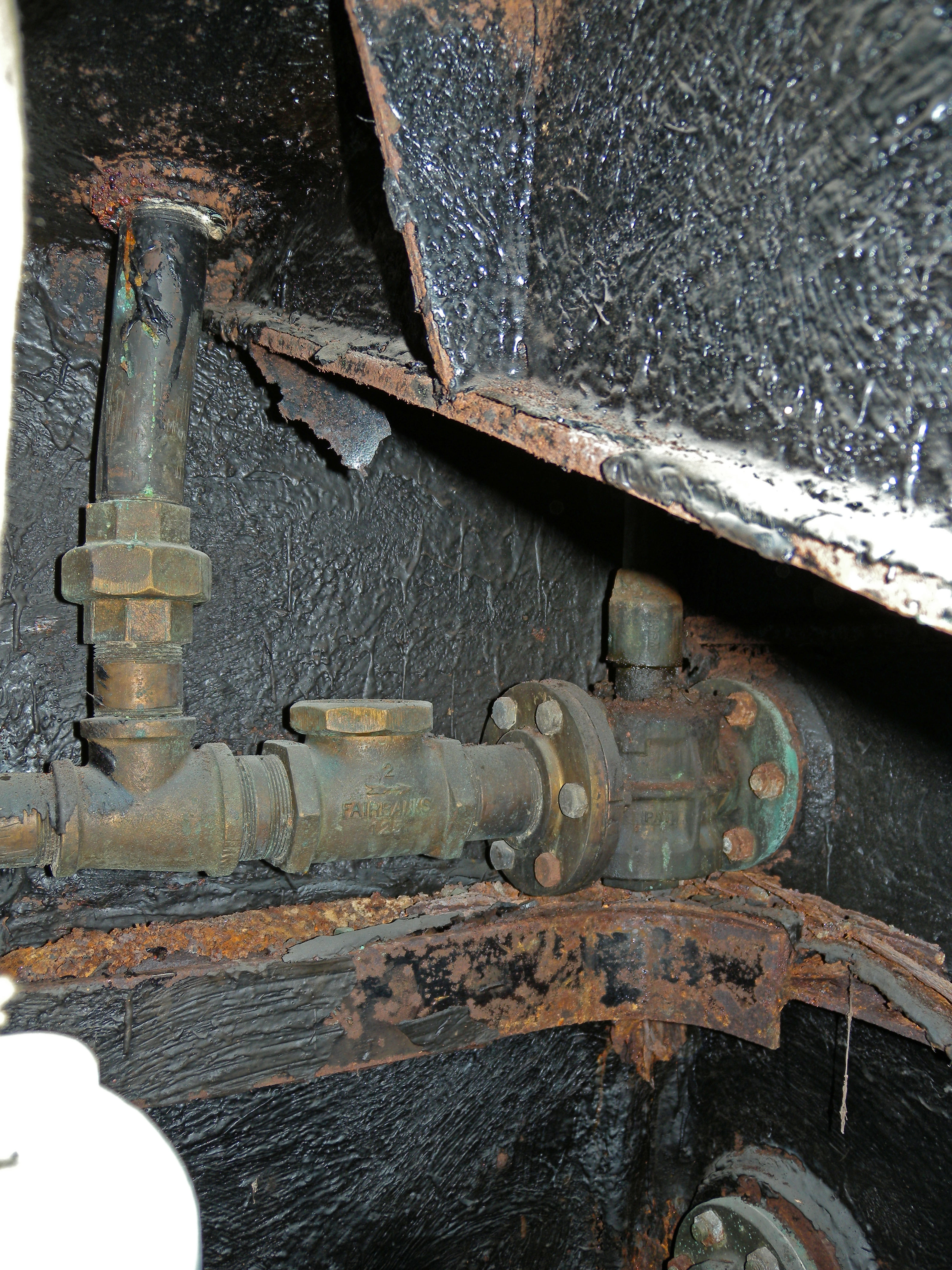 DSCN1177.JPG Drain from scullery above, drain from between heads left, T, check valve, tank stop valve, sanitary tank 2 on right.
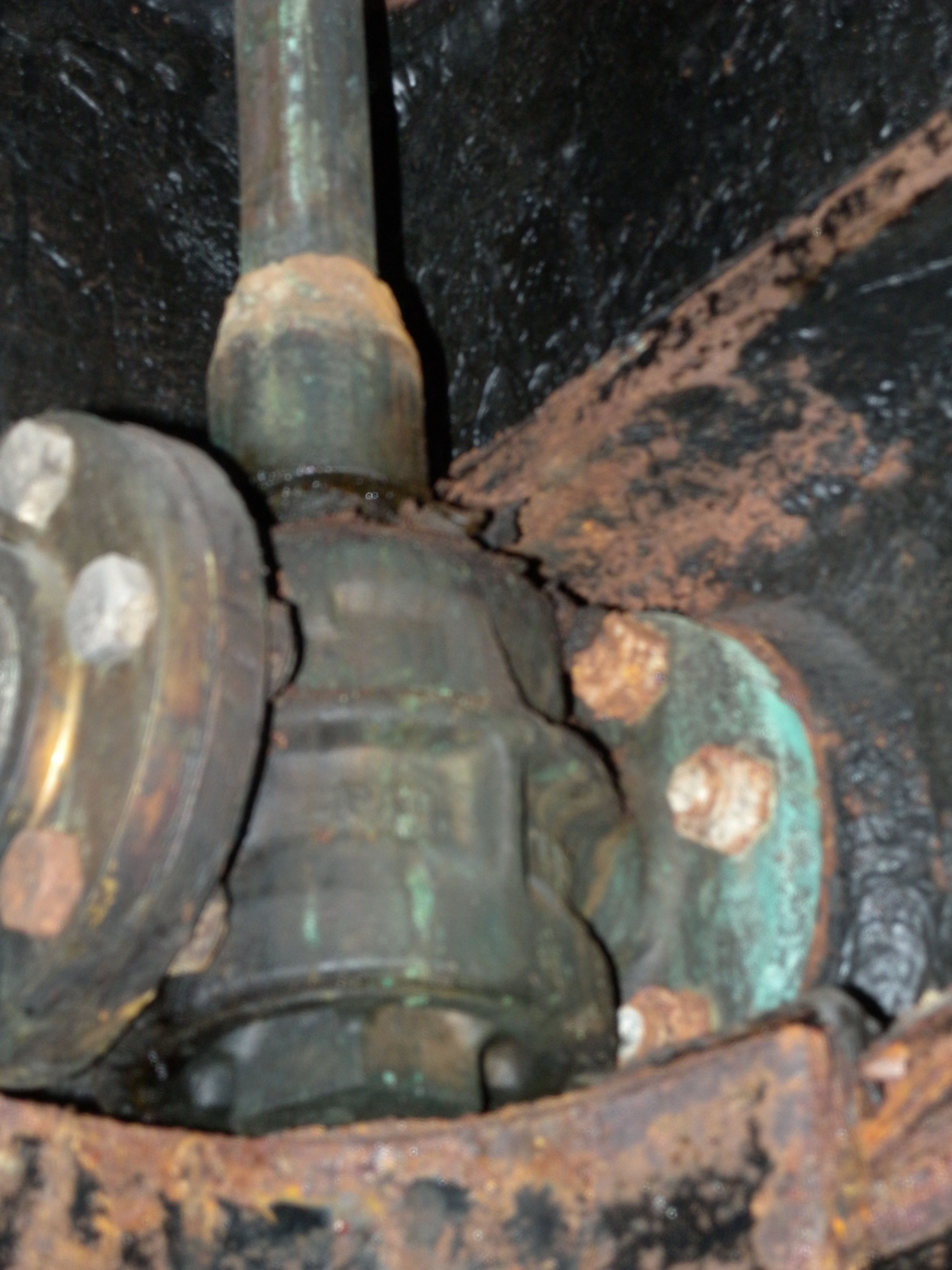 DSCN1179.JPG tank stop valve with reach rod
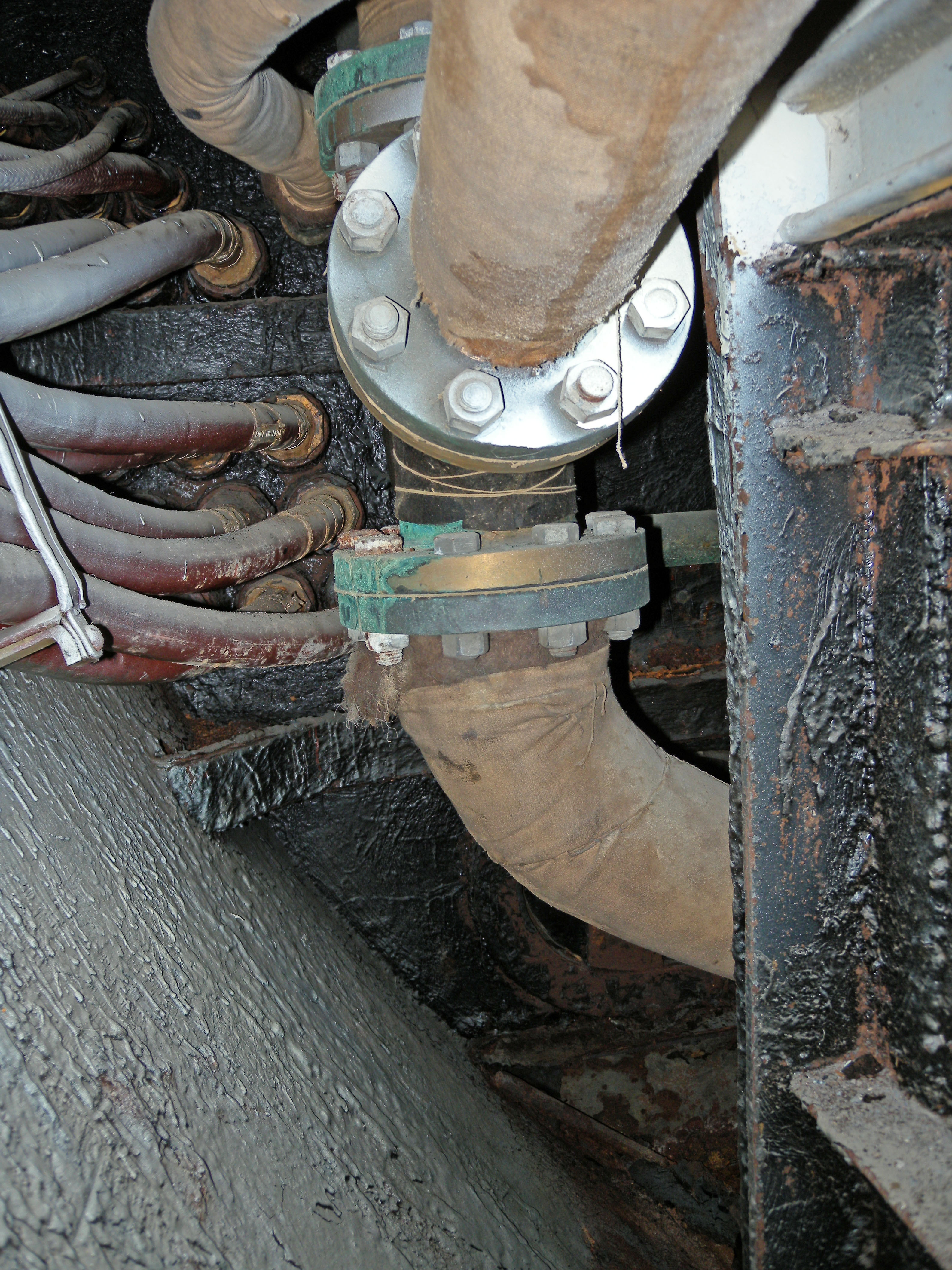 DSCN1180.JPG y between both heads, drain down to tank. No valves on heads.
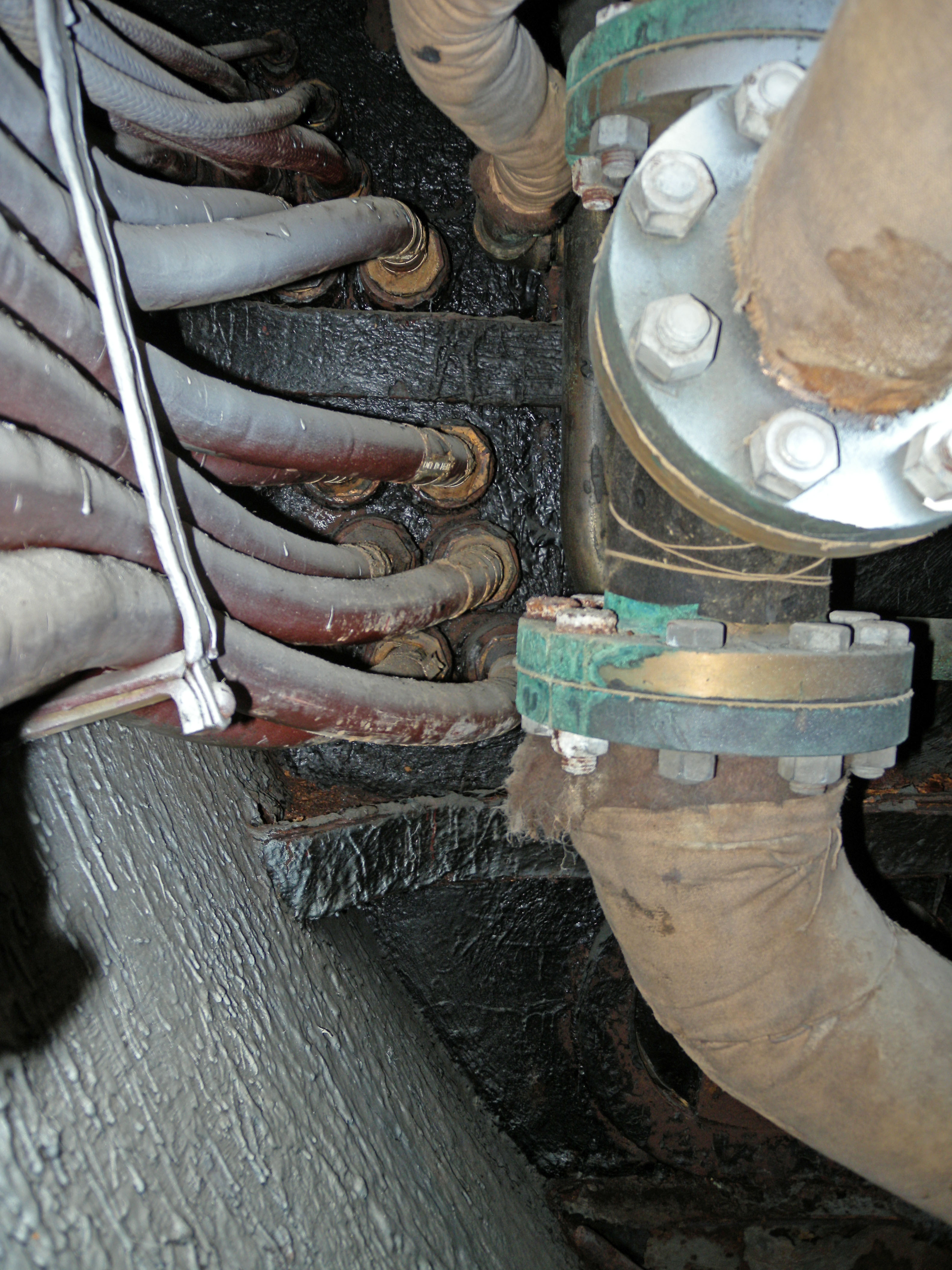 DSCN1181.JPG
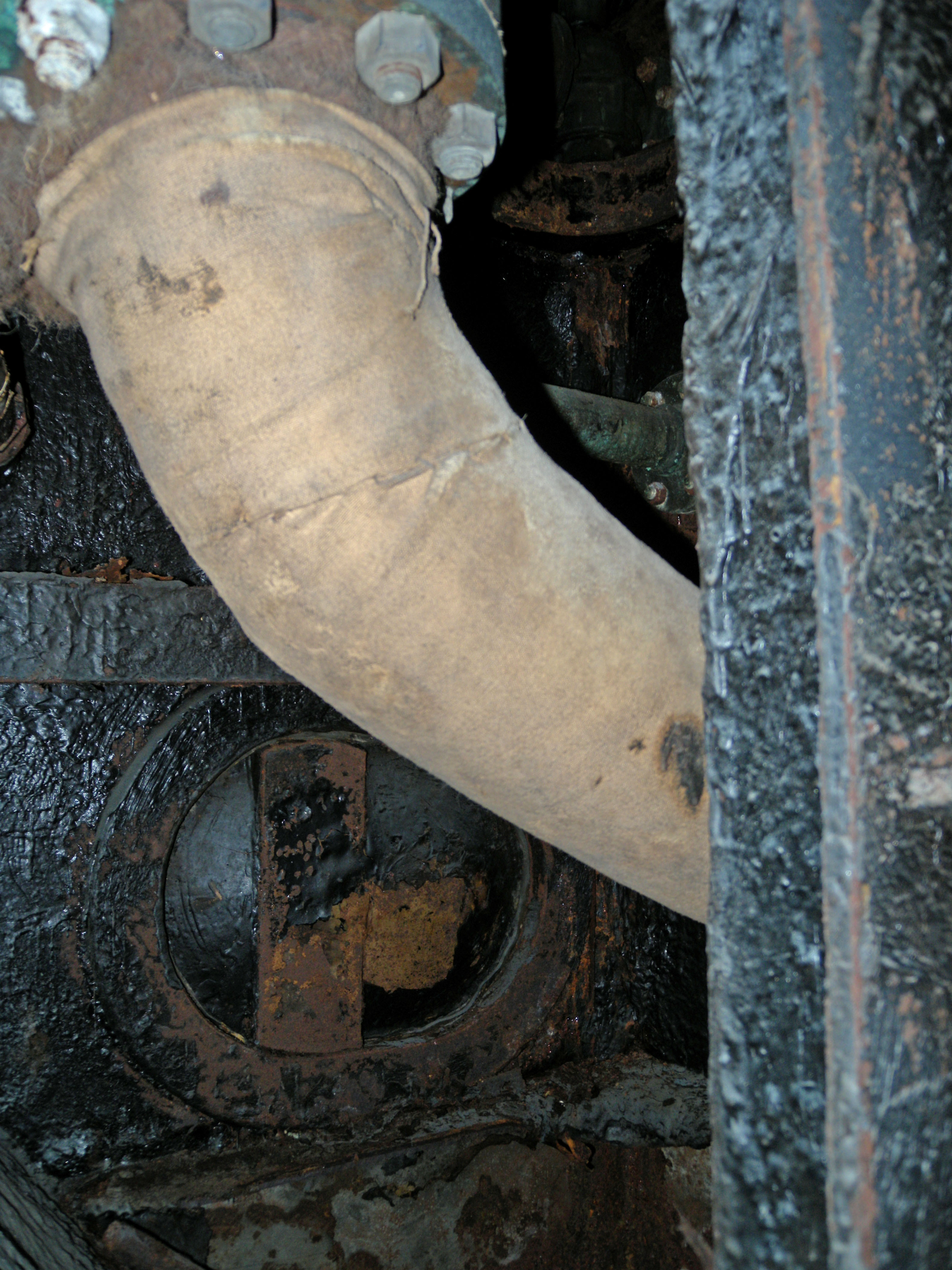 DSCN1182.JPG manhole, portable plate between void and forward engine room
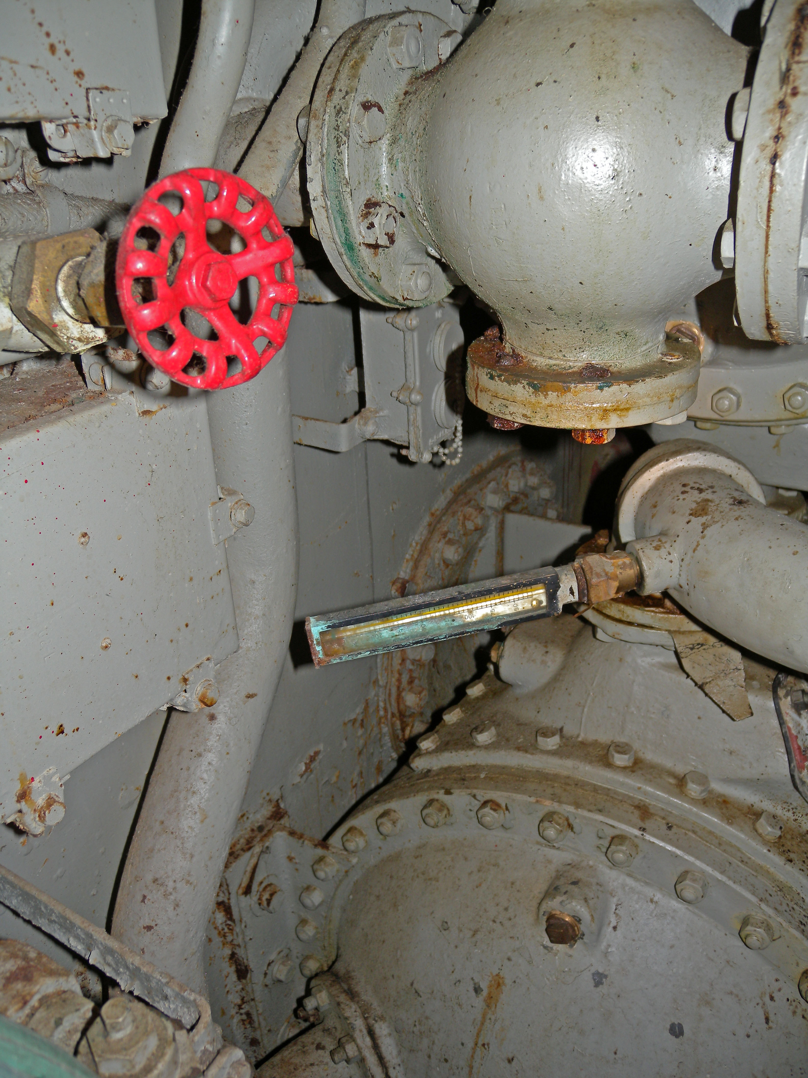 DSCN1188.JPG from forward engine room manhole to void
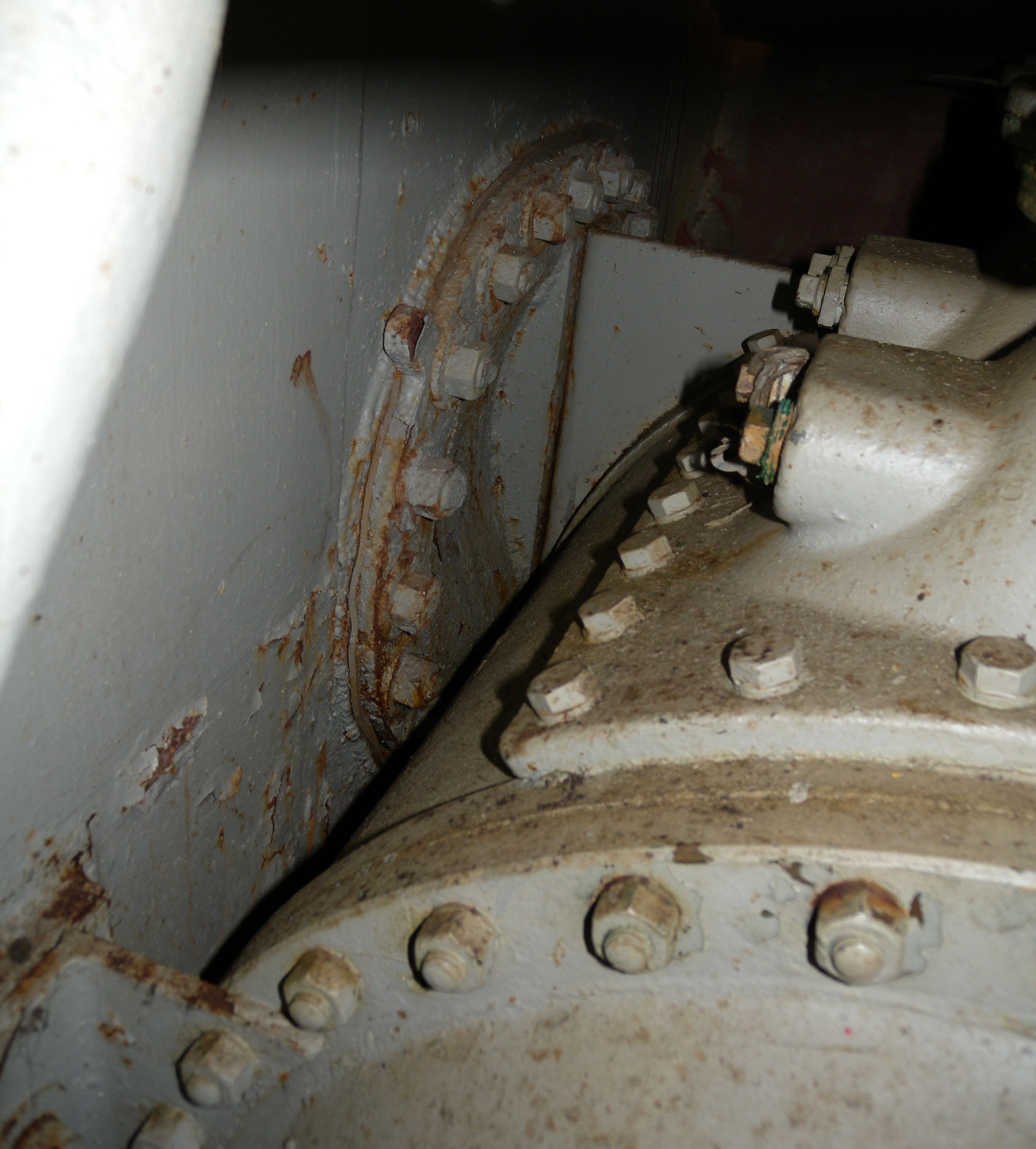 DSCN1189.JPG same, note the heat exchanger is mounted on the plate
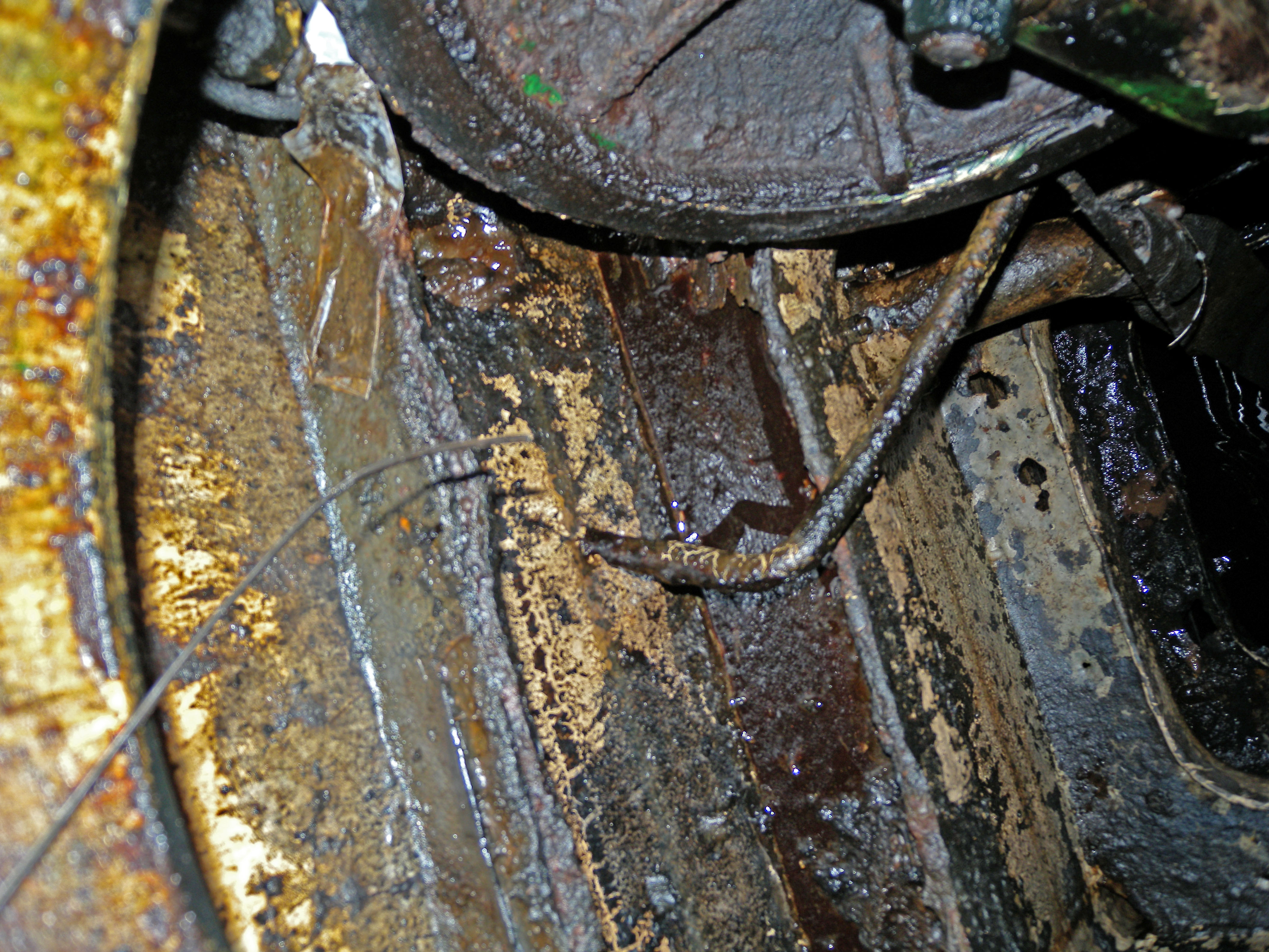 DSCN1190.JPG sanitary tank
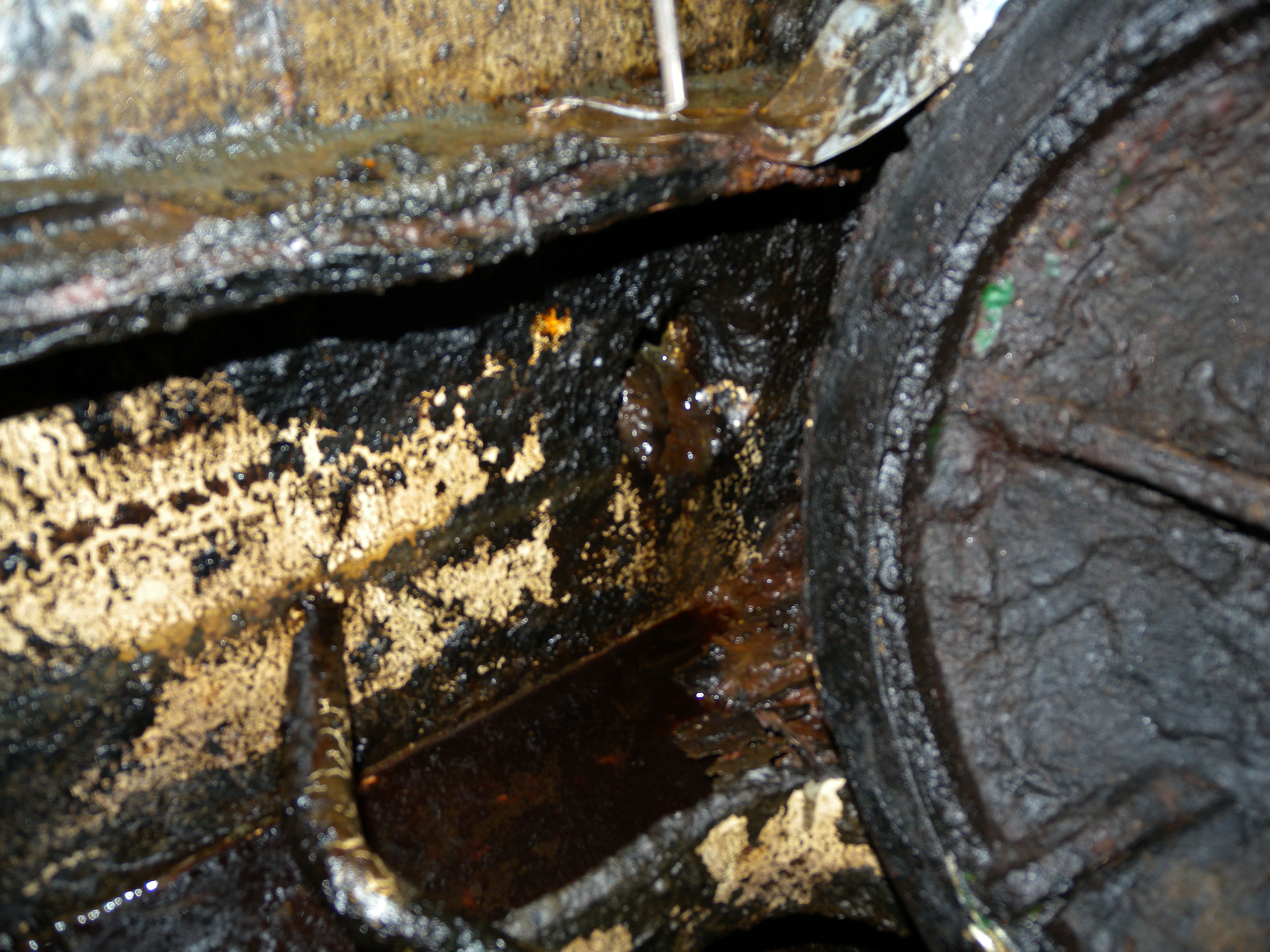 DSCN1191.JPG stb drain entrance
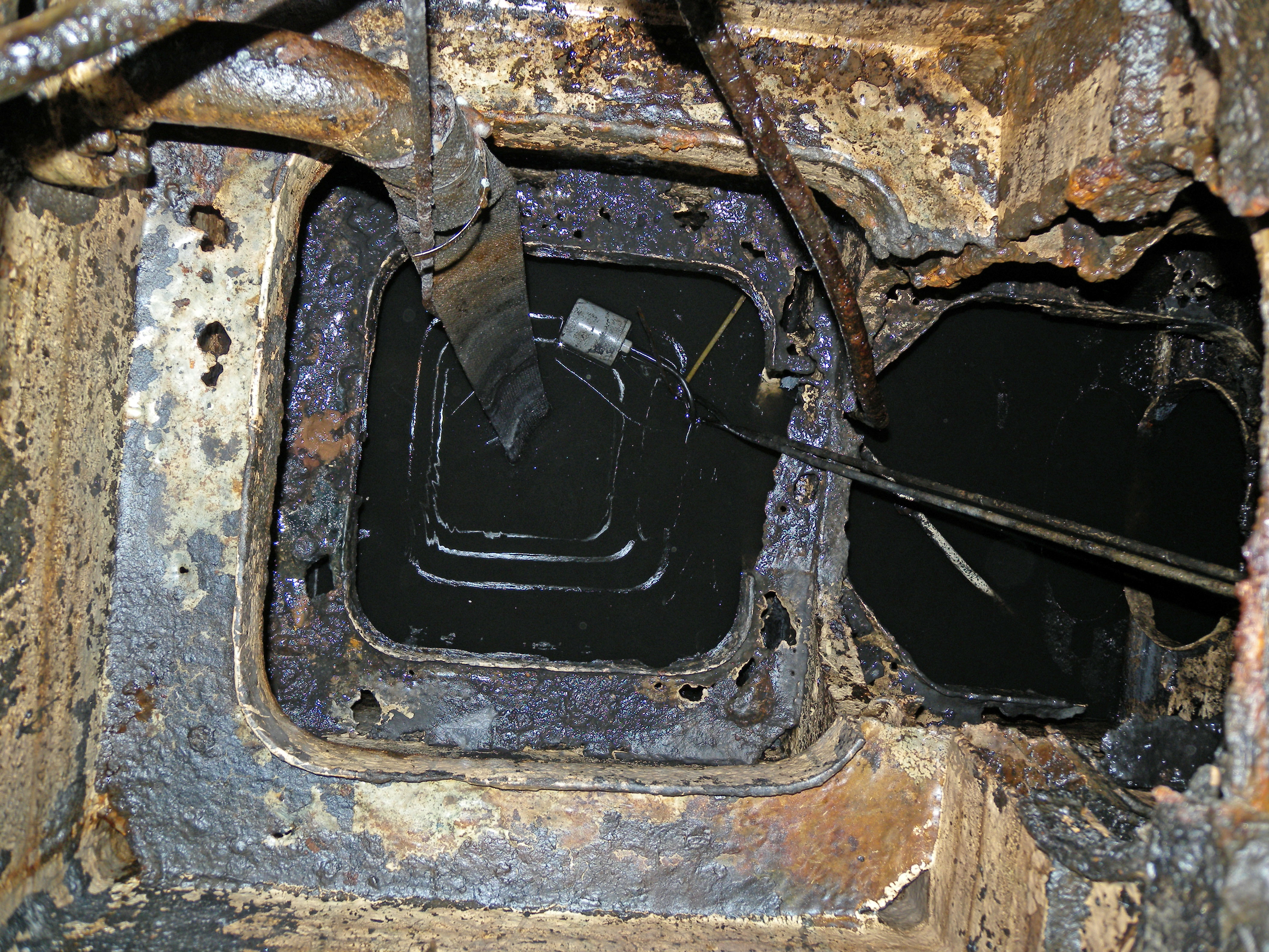 DSCN1192.JPG tank discharge
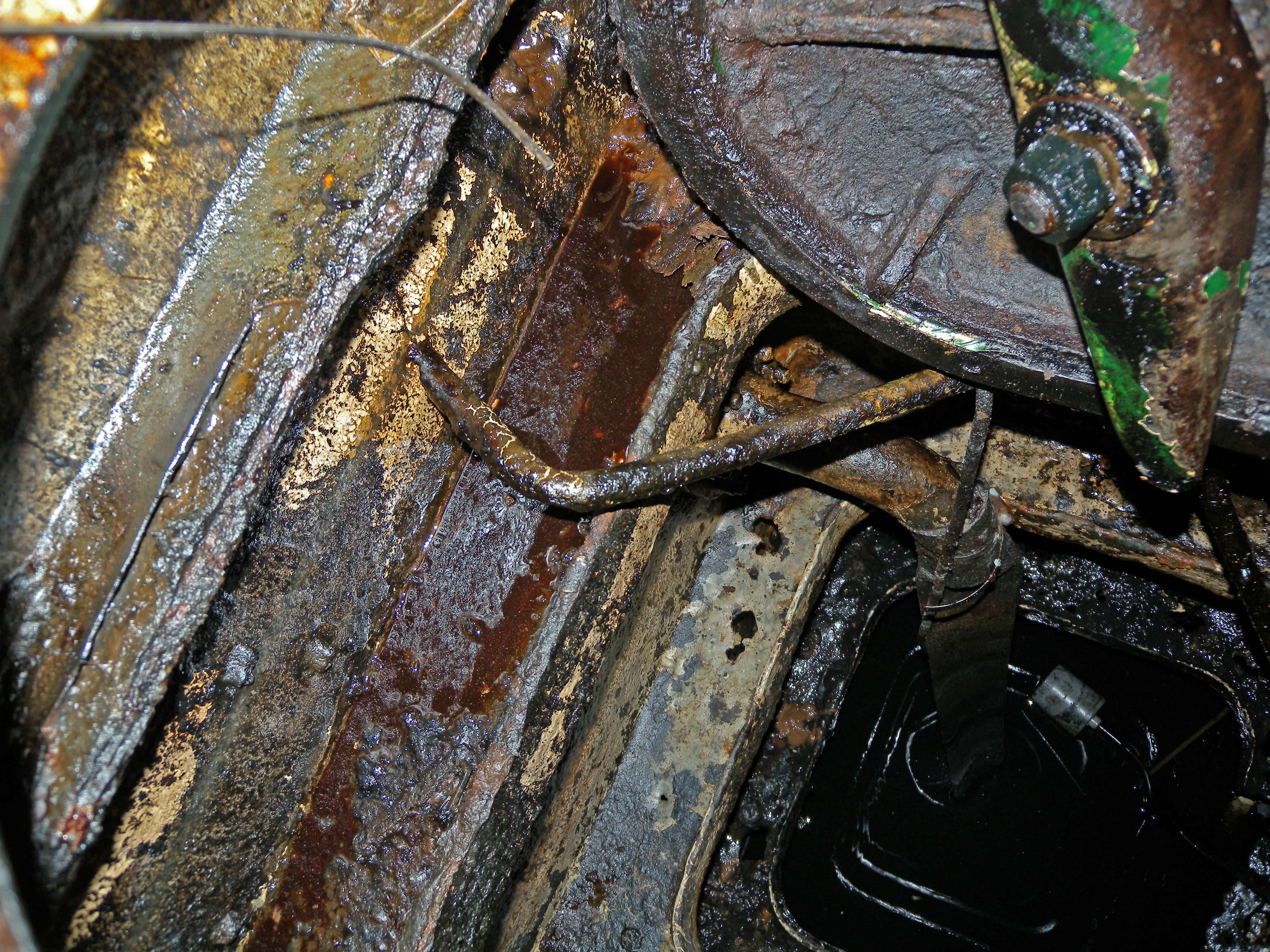 DSCN1193.JPG sanitary tank
 DSCN1194.JPG sanitary tank
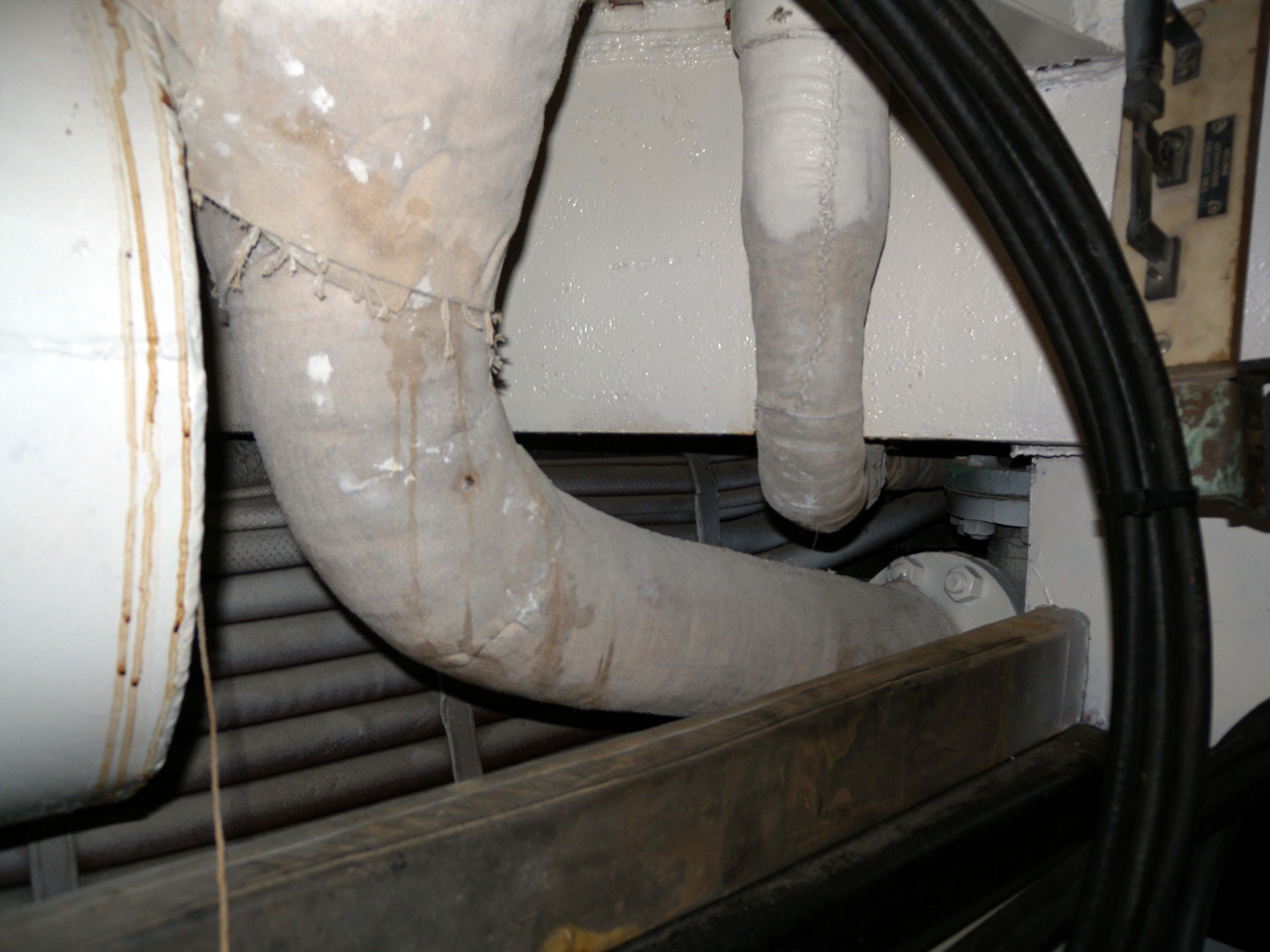 DSCN1195.JPG head drain, deck drain in battery
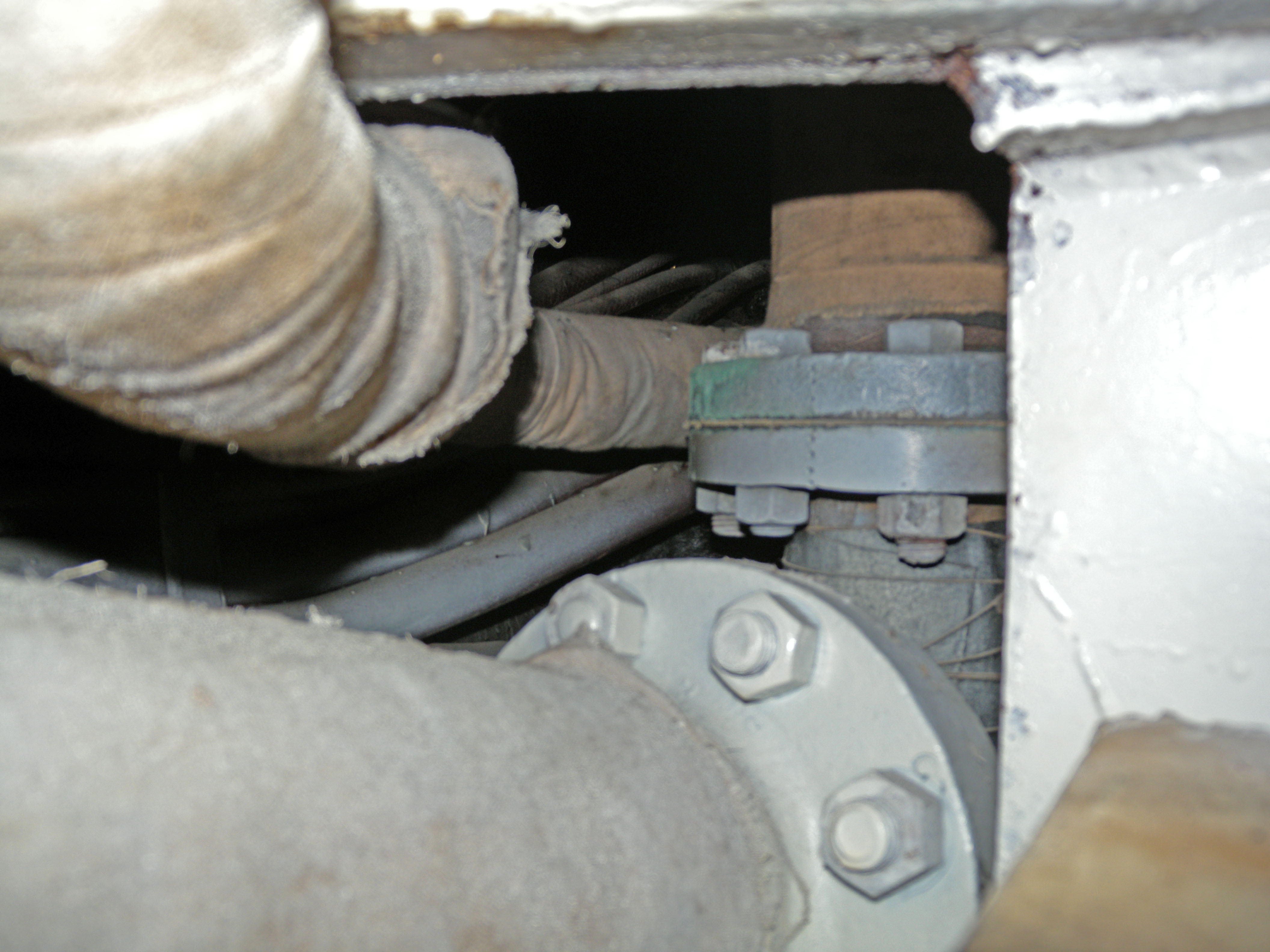 DSCN1196.JPG same
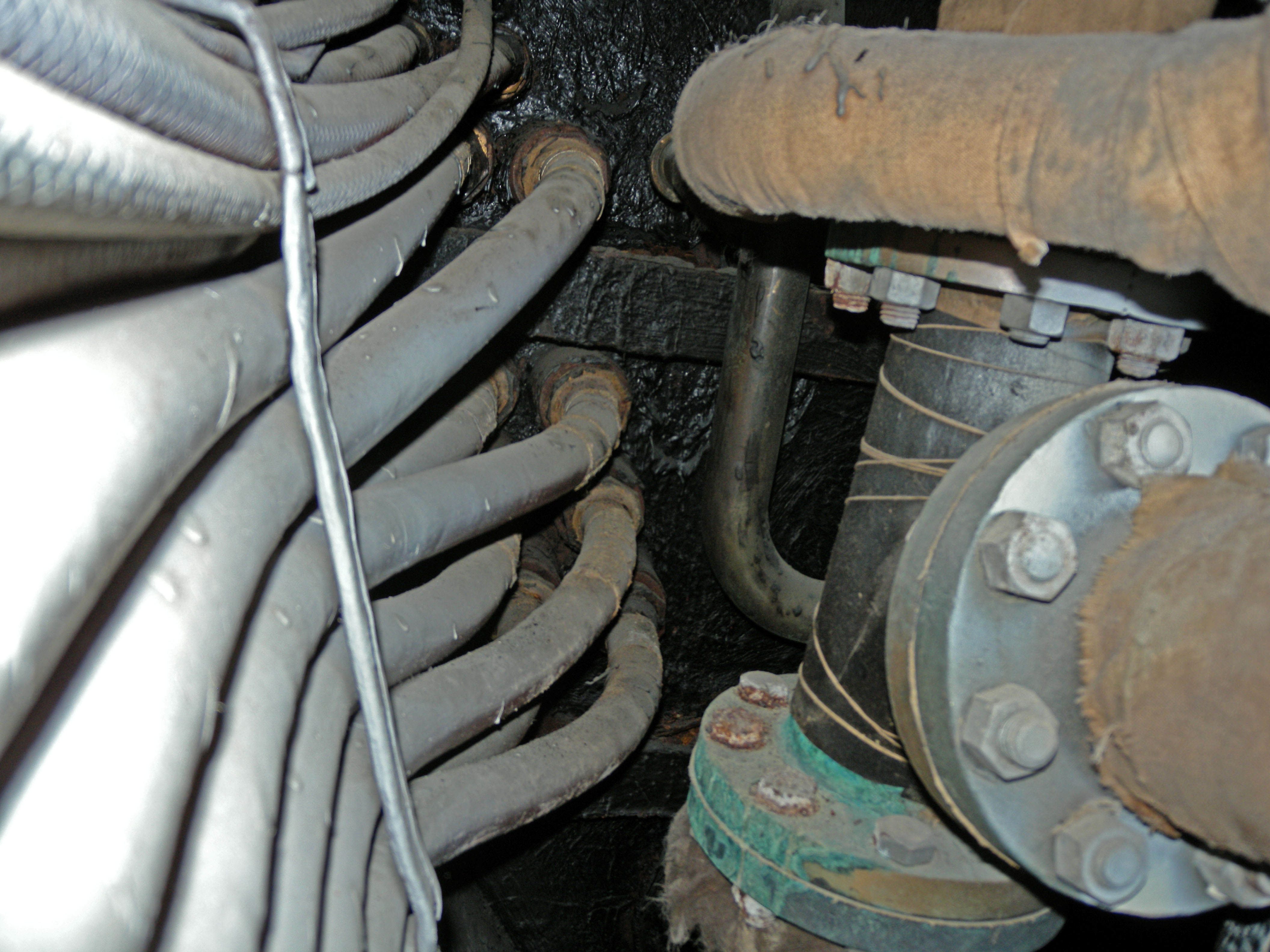 DSCN1198.JPG top right is deck drain line, small pipe down is tank discharge, big pipes on right are head drains
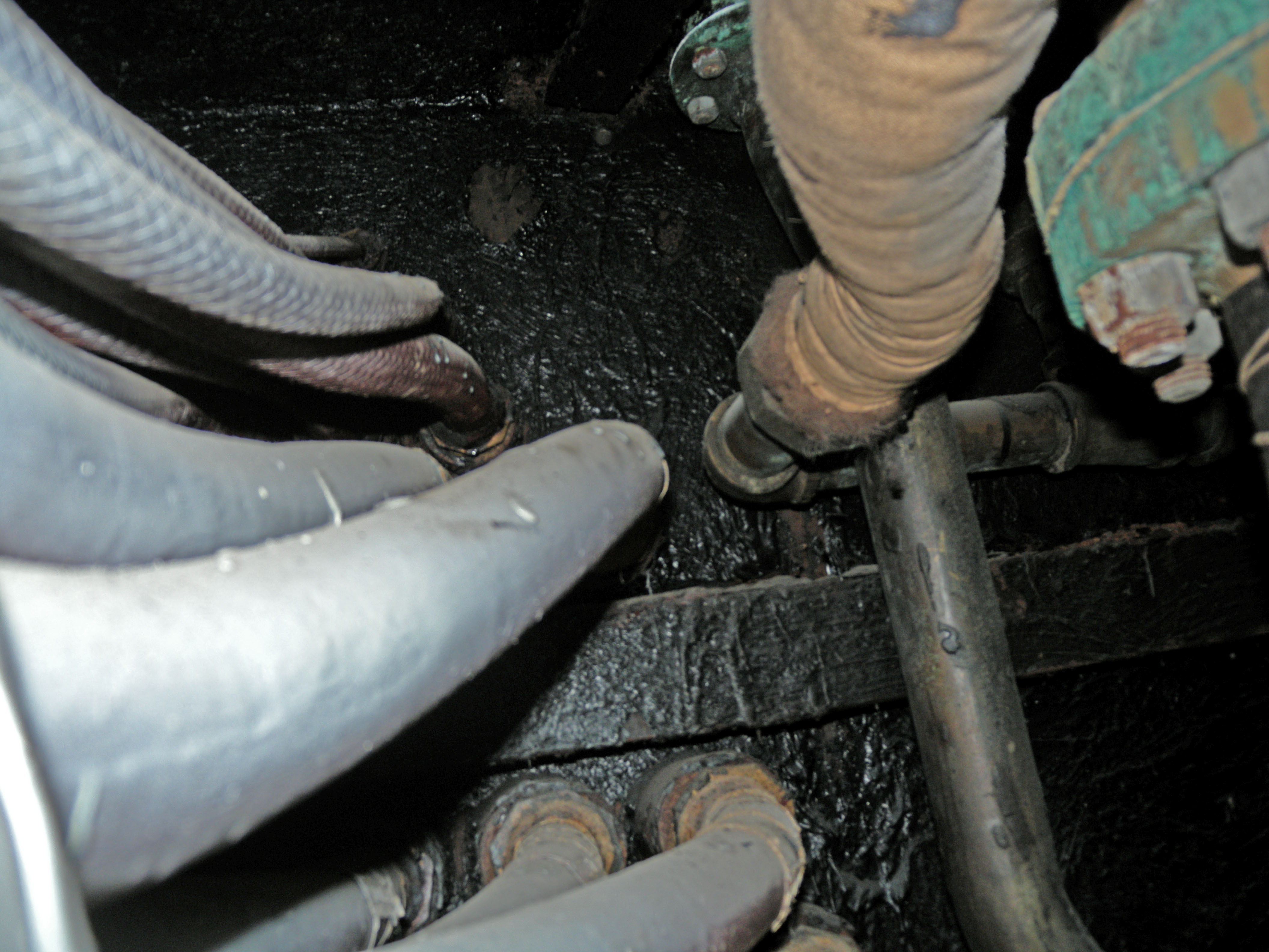 DSCN1200.JPG
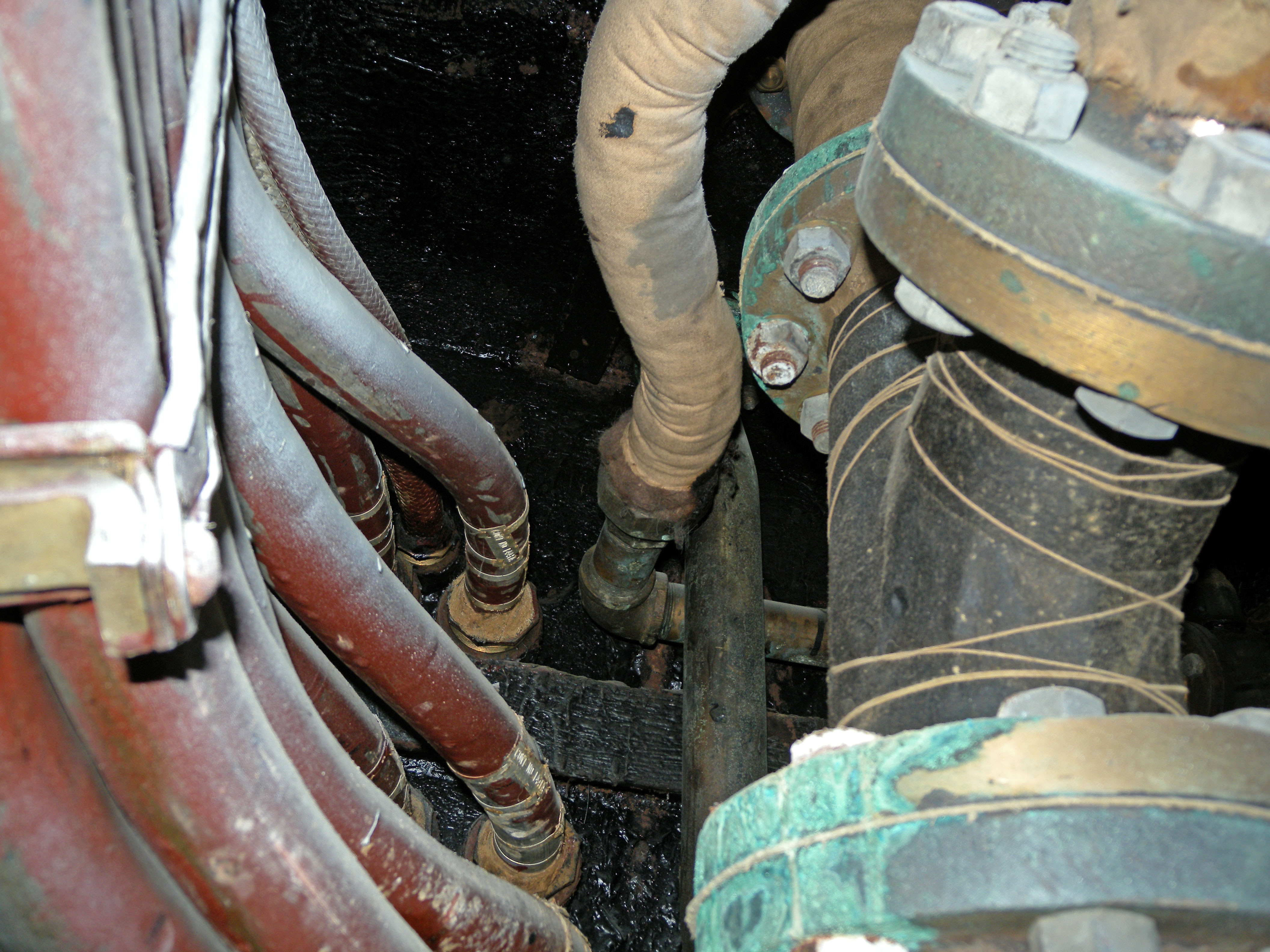 DSCN1201.JPG same, note the right angle on the deck drain
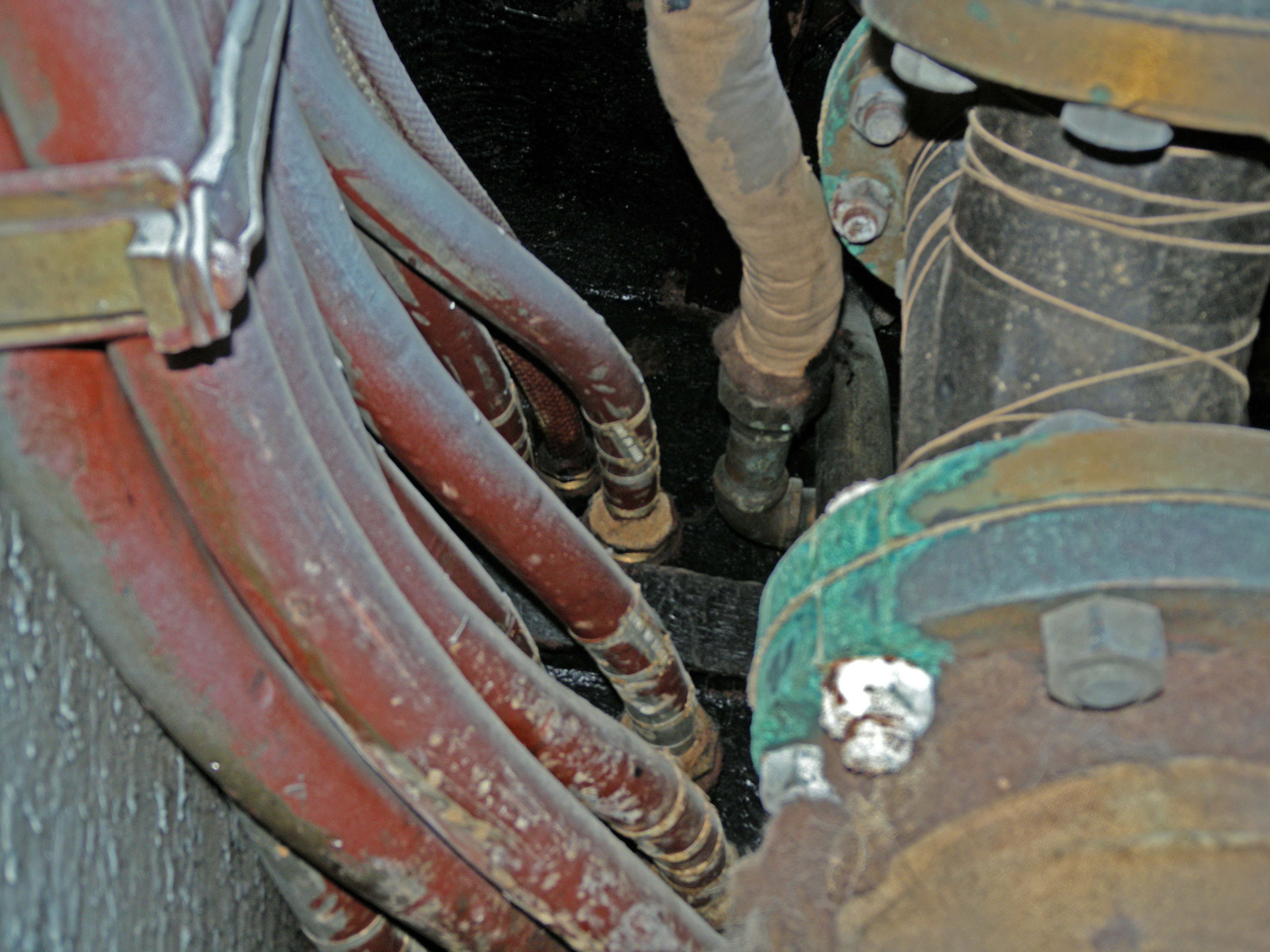 DSCN1202.JPG
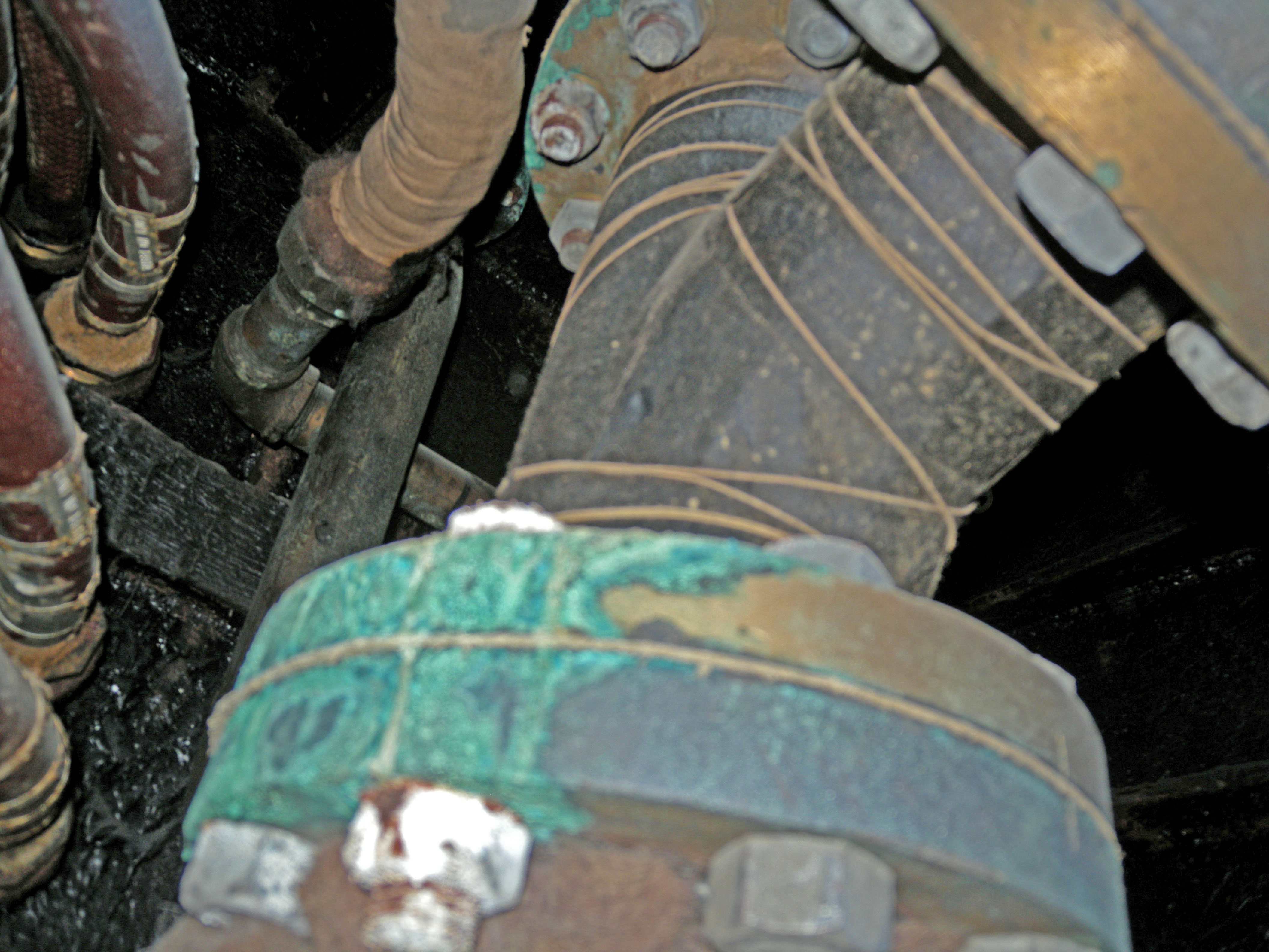 DSCN1203.JPG
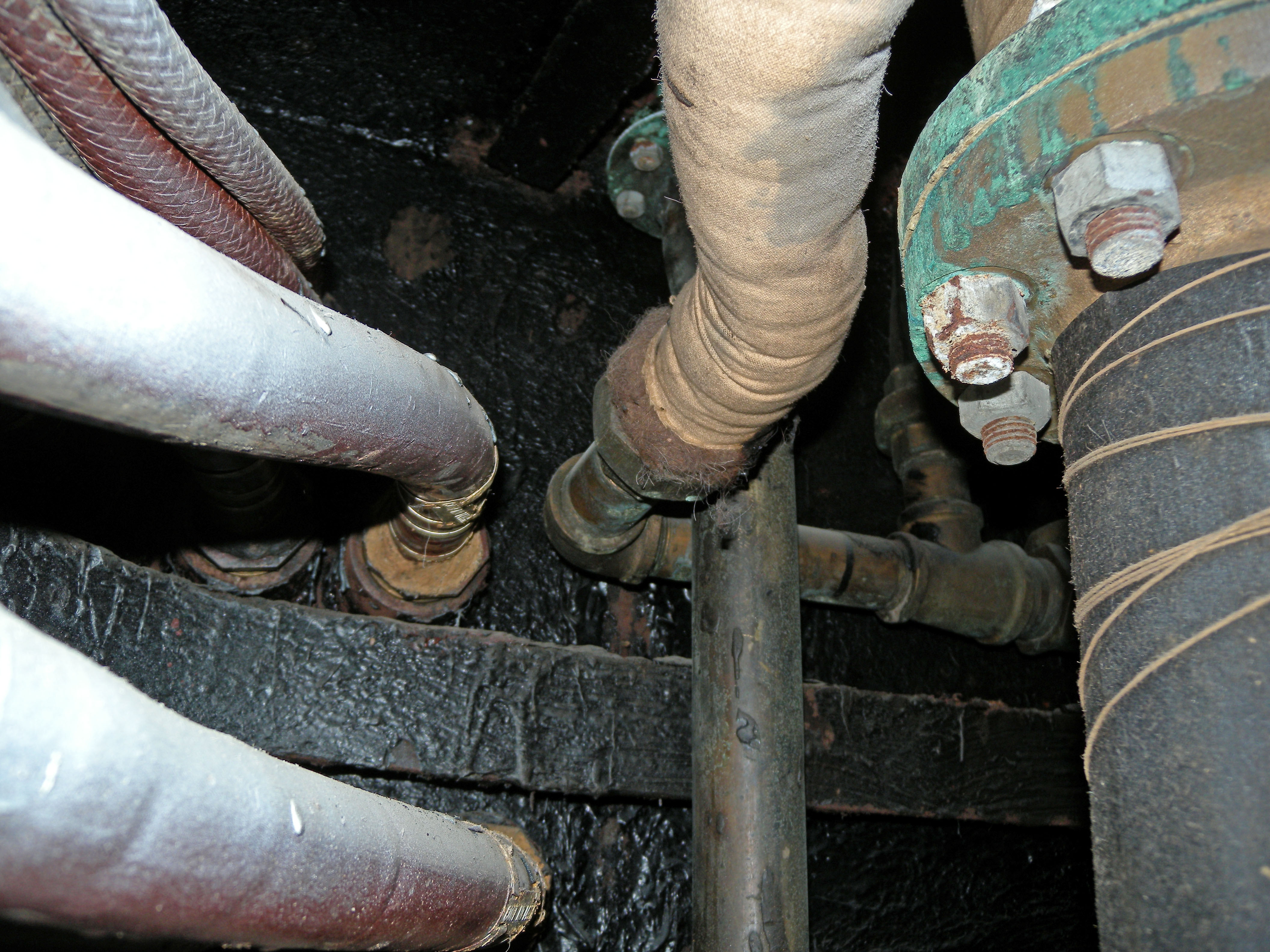 DSCN1204.JPG
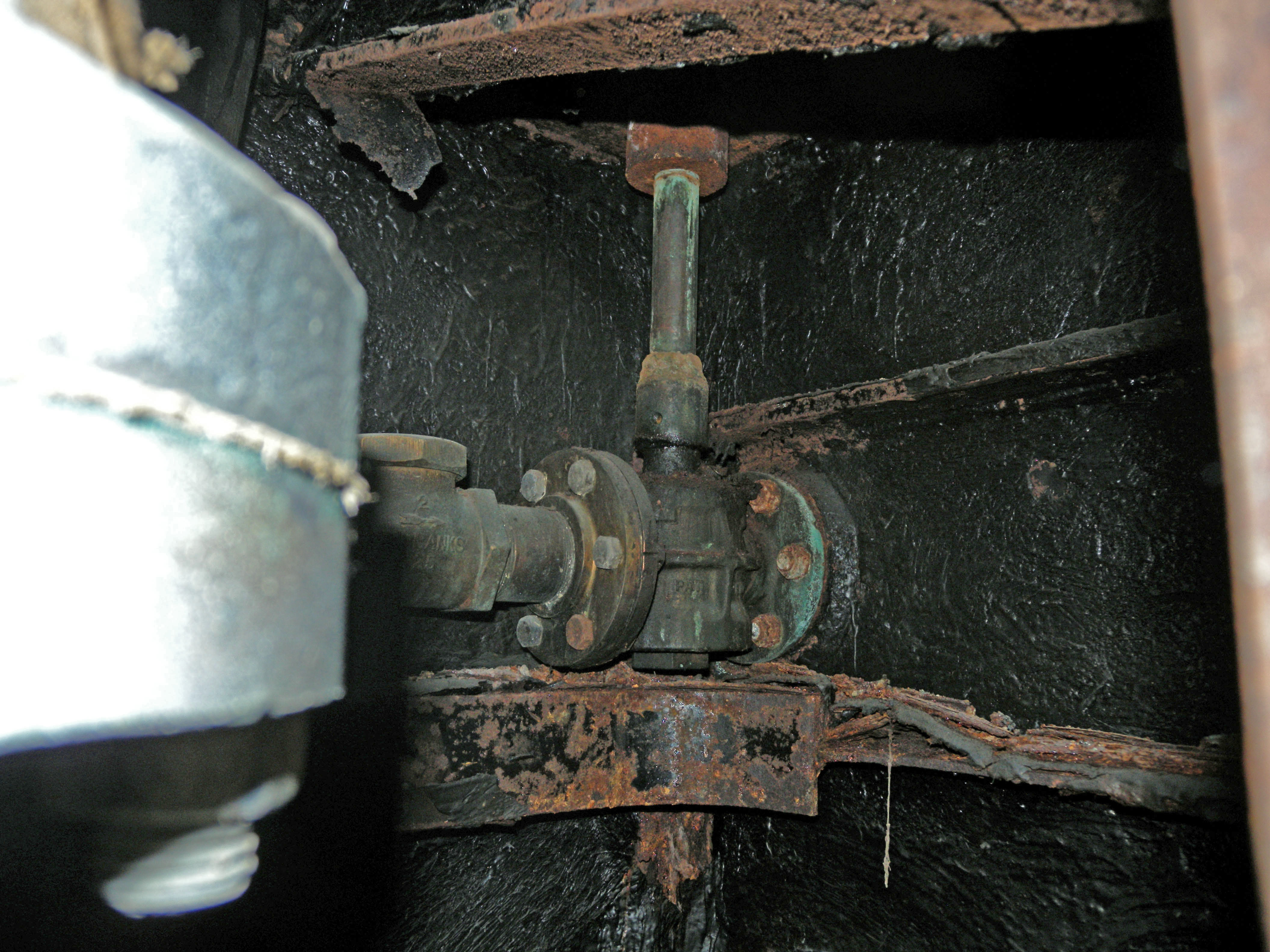 DSCN1205.JPG check valve, stop valve and reach rod
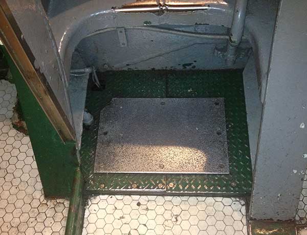 step-IMG_0556.JPG
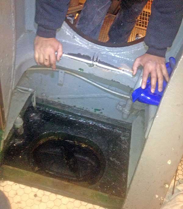 manhole-IMG_0562.JPG , 16"x12"
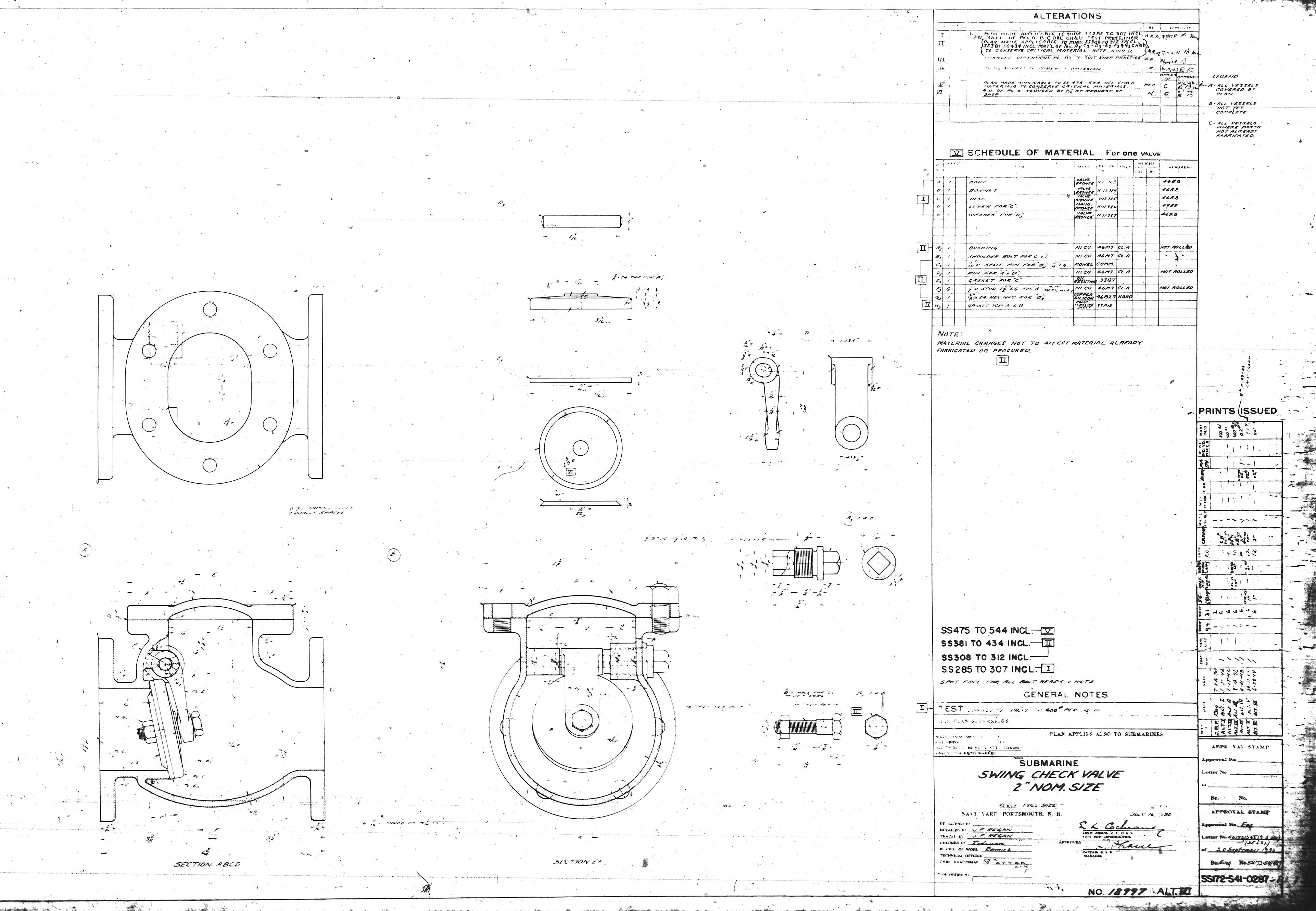