USS Pampanito Clinometer Replication Project 2011
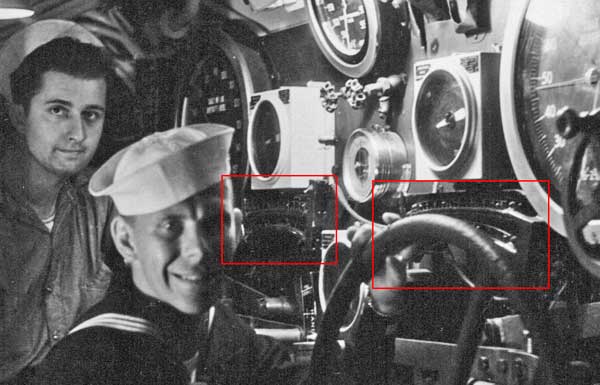
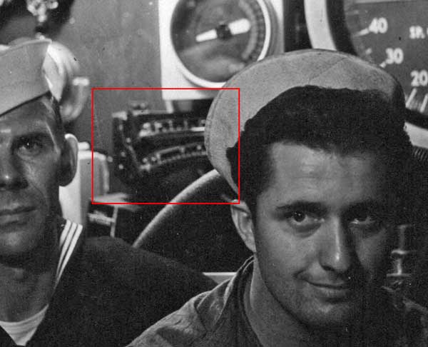
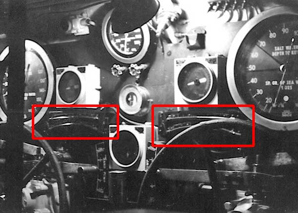
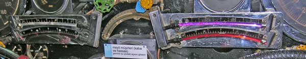
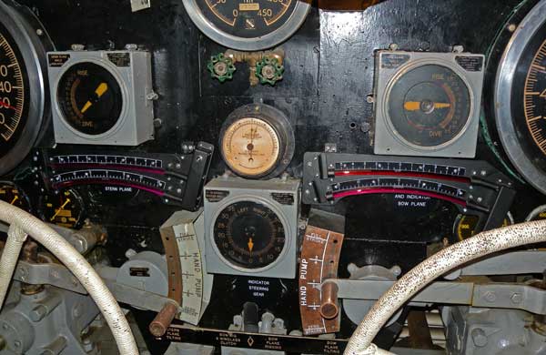
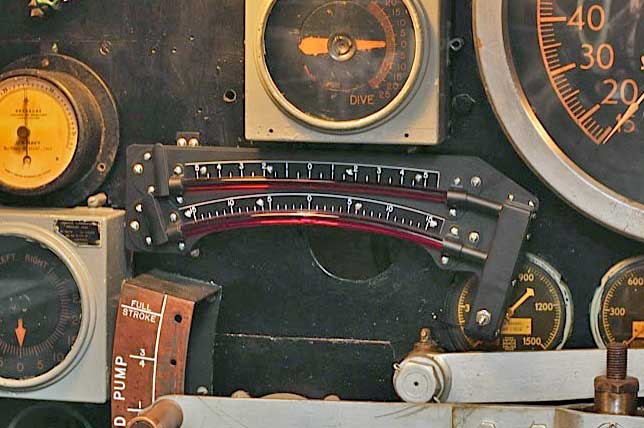
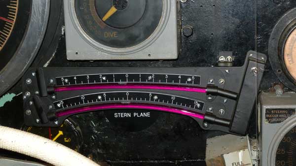
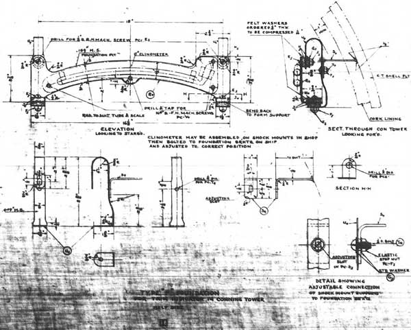
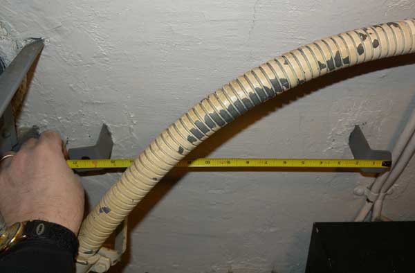
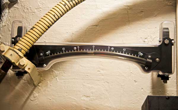
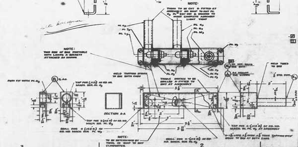
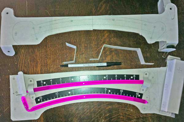
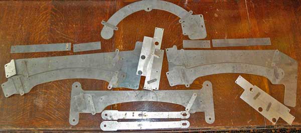
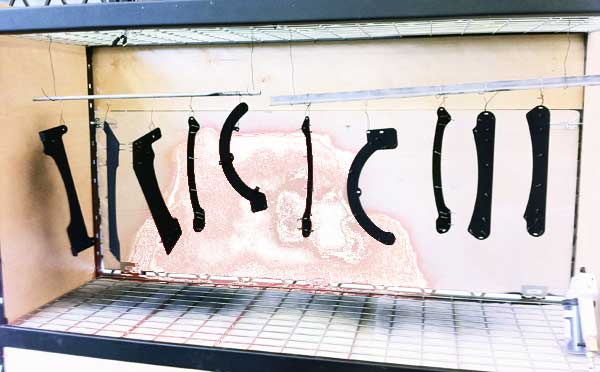
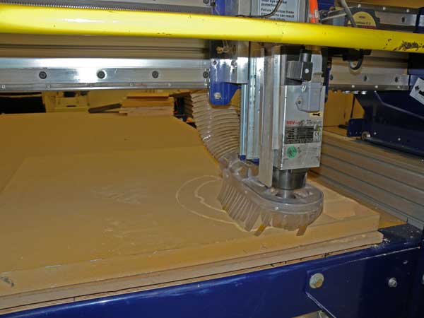
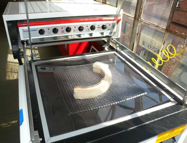
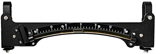
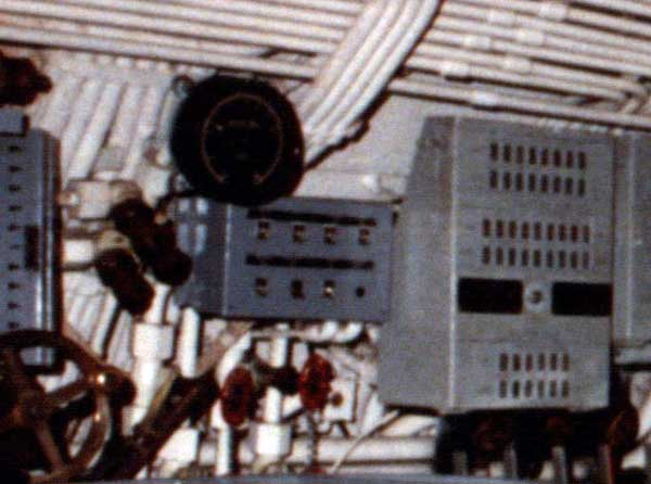
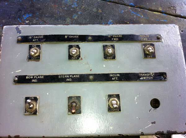
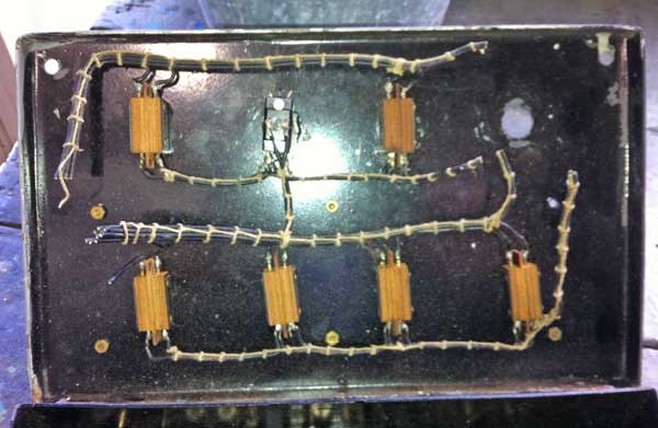
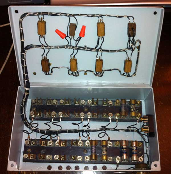
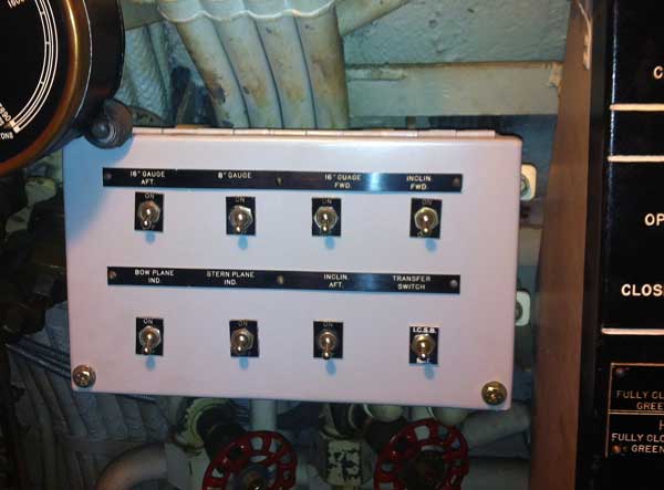
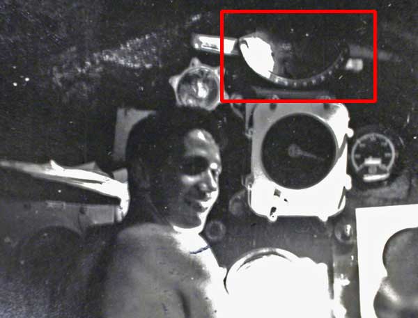
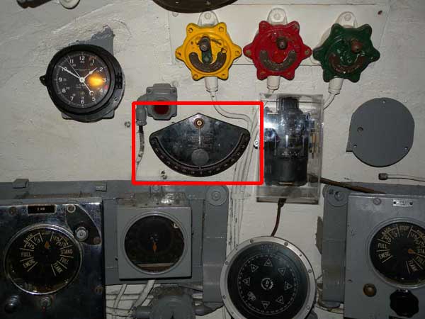
USS Pampanito is a WW II submarine museum and memorial on Fisherman's Wharf in San Francisco. The boat is owned and operated by a non-profit and receives no government funds. Our preservation goal is to make the submarine as complete and accurate as possible. Up to now (restoration started in 1981) we have been able to find most of the missing parts on the boat and have done relatively few replicas. However, it has been over 20 years and we had not found the clinometers (spirit bubble angle indicators). This note is a description of the project to replicate them and a heartfelt thank you note to the many individuals and corporations that helped make it possible. The importance of the clinometers to the submariners that operated the boat is hard to overestimate. Accurate depth control was critical to the safety of the boat at all times. The bubble clinometers used in conjunction with the depth gauges enabled the planesman to use dive planes (like flaps on an airplane) to control the depth of the submarine. One was used to measure the roll (side to side heeling) of the submarine. We believe that all 6 were removed in the 1960s when Pampanito was used as a shore side trainer and electronic simulators where installed in place of the real gauges (the boat has not dived since 1945.) Since Pampanito became a museum in 1981 we have searched for real instruments to replace the simulator parts. We successfully found real submarine depth gauges (also incredibly rare), but not the clinometers. For about twenty years, every time we met I was greeted by one of our submarine veteran and museum board members with the question, "When are we going to find the bubbles?" It became a running joke, but with Neil Chaiten's passing we decided to create the replicas. We began with research on the correct type and mounting. This started by completing an index to scanned microfilm of drawings from 1943 and 1949. The index allow us to find drawings of some of the parts. Having two versions of the same drawing was important because neither copy was fully legible, only with both could we piece together a mostly complete drawing. It continued with locating photos from other surviving museum submarines, measuring the holes and paint patterns on the Pampanito gauge boards, and eventually finding two photos with the clinometers in the background at the dive station on Pampanito from WW II. After photo-enhancement the WW II photos where very interesting because they showed that the gauges where moved from the original location, they are positioned differently than the drawings and other museum submarines and have significantly modified form. The good news was that the photos matched the hole pattern on the gauge board. After the project completed we found a third photo from the war that confirmed our design. We also found the foundation for the heel indicator (side to side motion) that was original to Pampanito, but had been removed earlier in the museum period. Once we had coherent best guesses for the design, we created our first CAD drawings. The research continued to source the parts we knew we could not make ourselves. We had three of the six needed glass indicator tubes that were recovered from surface ships in the Susuin Bay Reserve Fleet (mothballed ships). We then found the last manufacturer of these tubes in the USA. Reiker Instruments started building inclinometers in 1917 when they figure out that sealing the alcohol filled glass tubes within a vacuum prevented explosions (a very big deal to the glass blower). They also explained to us that the red dye was added to the alcohol to discourage the sailors from trying to drink it. Although the new tubes were slightly thinner than the WW II tubes they are created with the same methods and the same materials. We located a sign engraver in Minnesota that was willing to work with us to create the laminated phenolic scales, and hand hole covers when local vendors did not have the patience to draw the intricate scales. At this point we were able to adjust the drawings and we created paper/cardboard mock ups of the mounts. We found some, but not all of our drafting mistakes. These were the volunteer's first CAD drawings and they were first created in 2D. We wish we had done full 3D drawings to begin with. We later created 3D drawings of some of the parts where the sheet metal bends were not correctly calculated while lofting the 2D drawing. We then found a local metal shop that would CNC waterjet cut the 38 sheet metal parts. This saved us a huge amount of time and created better parts than we inexperienced metal workers could have created. Around this time we received access to Techshop. Suddenly we had access to a professional grade tools, classes on using them, and another community of craftsmen for training and advice. This was critical because professional journeyman craftsman could bend our parts in a few hours, but we did not have volunteers with the skills. With Techshop we were able to minimize the paid work, this was essential to an expensive project that was entirely funded by volunteers. It also allowed us to develop new competencies that will carry on to many future projects (3D CAD, CAM with CNC router, CAM with laser cutter, sheet metal fabrication, milling, vacuum forming, powder coating, etc.) The next step was also new to the Pampanito crew, we used a CNC router to create a plug and custom vacuum formed covers to protect the delicate parts that will be exposed to curious visitors. Existing visitor proofing required extension and update. A classic ship project that one of the staff thought would take two hours for two people, and landed up taking two days with four crew. Finally, the clinometers were installed on 18 July 2011. While we where working with the engraver to create the scales we also created replicas of the three missing hand hole covers on the dive station so they were installed at the same time. During Feb 2012 we found switches with the WW II style handles and we replaced the switches on the clinometer to be just a bit more accurate. After the clinometers were installed we needed to get power to the emergency gauge lights. When the boat became a museum in 1981 the emergency gauge power was supplied by a distribution box next to hull opening indicators. The power to the box was still supplied from a 6 volt supply on the IC switchboard, and from a battery box below the dive station with the original wiring. At some point early in the museum period this box was removed, all of the wiring that lead to the gauges was pulled out, the wiring in the box was cut and mostly removed, and the foundation it mounted to was cut off of the hull. Fortunately, the fools that did this did not throw out the box and we found it in our collection. Because the tank behind the hull is not easily emptied and tested gas free we could not weld a replacement foundation on the hull. Instead Ralph W. created a foundation bracket to hold the box that attaches to a pair of wire hanger threaded standoffs. We then had to replace the cut wires, one missing switch, one damaged (melted) switch, a missing label and badly damaged paint. This was completed in Oct 2011. At this point only the clinometers have been wired in, but eventually the other emergency lights for the gauges will be added and wired in. PENDULOUS HEEL INDICATOR IN CONNING TOWER: We have a photo from 1944, before the big summer of 1945 refit, that shows a pendulous clinometer used as a heel indicator at the helm in the Conning Tower. However, we have no photos from this area after the refit. We do not know if the heel indicator was moved or removed during the refit. Many pieces of equipment did move, for example the log indicator. If they moved it, it would still have to be athwartships, but not necessarily near the helmsman. Unfortunately, the most likely locations are at both ends of the Conning Tower and these were "repaired" with sheet rock compound and paint sometime early during the museum period obscuring any clues. In Feb. 2012 we created a replica foundation that attaches to existing, empty, threaded studs at the helm. This allowed us to mount a replacement (built in 1942) pendulous clinometer without any changes to the historic fabric of the submarine. The change is easily reversible if we find some post refit photos. We believe this is the last of the missing clinometers aboard the boat. It is hard to express how much we appreciate the advice, help, donations and discounted products and services from individuals and companies along the way. We had the help of an very talented team. We could not have succeeded without the incredible generosity of these people and companies: ADVICE AND HELP:
Volunteers and Staff of USS Pampanito, https://maritime.org/sub DONORS:
Techshop, http://techshop.ws PROVIDED PRODUCTS AND SERVICES AT DISCOUNT:
Conical Tool, http://www.conicalendmills.com/ SOURCES OF SPECIALTY PRODUCTS:
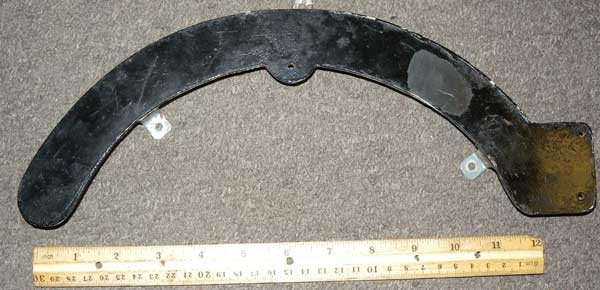
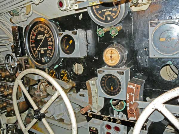
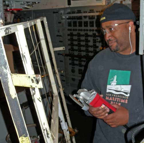
Reiker Incorporated, http://riekerinc.com Rich Pekelney, Pampanito Volunteer was the project manager. 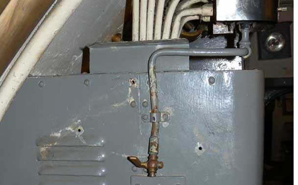 Location of heel indicator near low pressure manifold before installation.
EMERGENCY GAUGE LIGHT POWER
PENDULOUS HEEL INDICATOR IN CONNING TOWER:
|