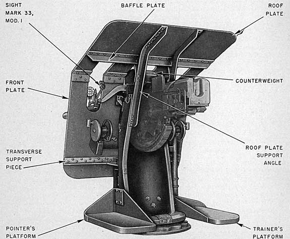
1. As enumerated in Appendix 1, certain of the mount assemblies are equipped with a shield, as shown in figure 31. This is a spray-type, 1/2-inch-plate shield which is mounted on the carriage to provide an element of protection for the pointer and trainer. These shields are employed in conjunction with the bar-type open sight. (See ch. VI.)
2. Shield.-The shield is a flat plane broken horizontally into two slopes. The lower half protects the mount and crew stations from the front. It extends upward from within approximately 26.0 inches of the deck, sloping to the rear at an angle of 17° with the vertical until the lower plane joins the upper plane. The upper section of the shield surface extends back
FIGURE 31.-3-inch Shield Mark 14, Left Rear View.
86
over the mount and the trainer's and pointer's stations to a point approximately over the breech face of the gun when at zero degrees elevation. This upper shield section slopes upward at an angle of 19° with the horizontal. The two shield surfaces are 71.0 inches wide and are joined by being riveted to a common angle shape. The entire plate structure is mounted on and supported by the carriage, to which it is secured by angle shapes.
3. Gun port.-The gun port is located in the center of the shield. It pierces both the front and top shield surfaces, being extended up into the top face to permit high angle elevation of the gun. The port is 13.50 inches wide and does not effect weather closure with the oscillating assemblies of the mount.
4. Sight ports.-Sight ports are provided for the pointer's and trainer's bar-type open sights. These ports are located on either side of the gun port and in line with the pointer's and trainer's lines-of-sight. They pierce the front section of the shield and extend up into the top section. They are 8.25 inches wide and permit sight through the shield up to the limits of gun laying movement. These ports are open at all times and do not permit weather closure.
Maintenance
5. The shield assembly requires structural maintenance as specified by the Ordnance Manual. All surfaces of the shield must be maintained free from corrosion. Rust must be chipped and the exposed surfaces painted according to the instructions of the Bureau of Ships Manual as to the preservation of structure.
Installation
6. The following procedure is applicable for installing this shield on an otherwise completely assembled mount:
(a) Before installation, all stay rods and similar attachments used in shipping should be removed from the shield; also all fasteners used for securing the shield to the mount. Remove the right and left angles from the shield. The gun should be positioned at zero degrees elevation (approximately) for this installation.
(b) It is desirable to remove the pointer's and
trainer's open sight assemblies from the sight yoke in order to prevent the possibility of damage during the installation of the shield; this is accomplished by removing the bolts from the sight-bar cradles.
(c) Sling a lifting cable to the shield. It will be found convenient to attach the cable by means of two C-clamps (2 inches or heavier) that are secured at the edge of the roof plate about 6 inches from the joint with the front plate; with this point of application which may be varied if necessary, the shield should approximately" assume the installed position when lifted.
(d) Refer to figure 31. Lift the shield and move it carefully over the gun into position on the mount. Assemble the right and left angles to the shield. Block, clamp, rig, or frame the shield in position to obtain the locating dimensions required by drawing 241136 or 249709. Through the shield, locate the shield-securing holes in the carriage as required by drawing 245070. Then disassemble the right and left angles, remove the shield from the mount, and drill, tap, and spot face these holes as required.
NOTE.-When shield is on the mount, a check should be made that no interference between the shield and the slide. counterweight exists for any elevation of the mount. Should interference exist, it will be necessary to chip the counterweight in accordance with drawing 241974 (revision F) or drawing 246941 (revision A). Also the shield should cause no interference in the operation of the sight for any position of the sight and mount.
(e) Remount and secure the shield, sizing and installing the washers, drawing 241139-6 or 249708 4, as required. Faying surfaces
where the shield assembles on the mount should be painted for protection against corrosion as directed in Ordnance Standard No. 52. Replace the open sight assemblies; faying surfaces should be protected by the application of rust preventative compound, Navy Department Specification 52-C-18, Grade 1. Unless otherwise directed, the shield should be painted with Paint No. 2 (Ocean Gray) of Ordnance Standard No. 52. This will match the paint on the mount.
87
CHAPTER X
FUZE SETTING EQUIPMENT FUZE SETTER MARK 10 FUZE SETTER MARK 11 MOD. 1 FUZE SETTER MARK 11 MOD. 2 FUZE SETTER MARK 12
General Description
1. Mount assemblies are equipped with fuze setting devices as indicated in the Index of Assemblies, Appendix I. These installations include the several fuze setter designs of the above title. They are mechanisms for setting 3-inch A. A. ammunition, nose type, mechanical, 30-second time fuze. The settings are made manually in response to oral (telephoned) order or synchro dial indicated order. All designs employ two manual hand crank inputs: one for fuze scale setting, the other for engagement and positioning the fuze ring. The designs comprise two general classes, as follows:
(a) Fuze Setters Mark 10 and Mark 12.-These designs are "off-the-mount" assemblies, commonly located beyond the working circle and attached to bulkhead or other ship's structure adjacent to the mount emplacement.
(b) Fuze Setter Mark 11 modifications.- These designs are "on-the-mount" assemblies, located on the sight setter's platform extension of the carriage as shown on plate 1.
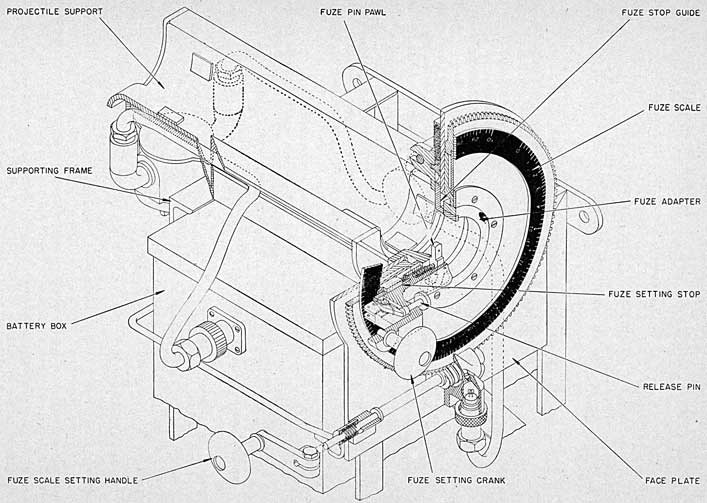
Fuze Setter Mark 10
2. Fuze Setter Mark 10 is usually mounted on the ship's adjacent structure. For those mounts carrying the combination sight-setter's platform and fuze-setting support bracket, however, this design may be satisfactorily mounted at the fuze-setter location by removing the mounting support provided for other fuze setter designs. Fuze Setter Mark 10 is for use with any 3-inch A. A. projectile fuzed with the 30-
573O5°-44-7
second mechanical fuze. The components and functional arrangement of parts of this fuze setter are illustrated by plate 16. Detail description and method of operation are given in separate publication: Ordnance Data No. 3645.
Fuze Setter Mark 11 Mods. 1, 2
3. Fuze Setter Mark 11 Mod. 1.-This fuze setter, illustrated and described in Ordnance Pamphlet No. 808, is a manually operated type which includes synchro receiver indicating dial mechanism, providing director fuze setting order. The unit is installed on the mount as shown on plate 1. It is adapted for fuze setting of any 3-inch ammunition equipped with 21-second A. A. powder train fuze, 30-second mechanical fuze, or drill ammunition.
4. Fuze setters of this design in service include certain minor changes made since the reference publication was issued. These changes provide a minimum fuze setting stop and replaceable pawl stops on the socket and drain holes in the case. The minimum fuze setting stop is a stop bar positioned to restrict the minimum setting to 0.60-second for the 30-second mechanical time fuze. The stop bar was designed to also provide a minimum fuze setting .stop when setting the 21-second powder train fuze. However, as this fuze is no longer issued, the adjustment of the stop for this fuze should be ignored.
5. Fuze Setter Mark 11 Mod. 2.-This fuze setter, illustrated and described in Ordnance Pamphlet No. 808, is mounted and operated in
88
PLATE 16 - FUZE SETTER MARK 10
89
the same manner as the earlier modification. It differs from that design in omission of the synchro and indicating dial elements; fuze setting orders are given orally. It may be converted to Fuze Setter Mark 11 Mod. 1 by changes and substitution of parts as described in the reference pamphlet.
Fuze Setter Mark 12
6. Fuze Setter Mark 12, described and illustrated in separate publication, Ordnance Pamphlet
No. 1046, is similar to Fuze Setter Mark 10. It is for use with any 3-inch A. A. projectile fuzed with the 30-second mechanical fuze.
Hand Setting Wrenches
7. In addition to the fuze setting instruments indicated in the text above, auxiliary hand operated fuze setting wrenches are provided. These wrenches are the design shown on drawing number 245748.
90
This page is blank.
91
CHAPTER XI
LUBRICATION INSTRUCTIONS
1. Foreword.-War conditions have imposed new problems as to lubrication maintenance of Ordnance equipment. The necessities of constant readiness and of operating the mounts daily through long periods together with the extremes of weather encountered in present operations have required new lubricants and a frequent change of lubricants. No standard oils or greases have been available that are universally adaptable to all conditions. This has been particularly true as to exposed deck mounts of the type of the 3-inch pedestal mounts described in this book. Extensive research to develop better lubricants and appropriate servicing instructions is in process. Accordingly, lubricating instructions as at present compiled on the appended charts are subject to change.
Mount Lubrication Facilities
2. All elements of all assemblies have design arrangements for initial packing or for replenishing lubricants. Wherever practical, the designs provide for retaining the lubricants, provided the prescribed oil or grease or a permitted substitute is used. The locations of all grease fittings, oilers, access covers, cover plates, filling caps and other points for applying lubricants are indicated on the lubrication charts. Precaution as to lubrication for many of the preceding indicated arrangements are prescribed under the "Maintenance Instructions" of the preceding chapters. These should be observed in addition to the instructions of the lubrication charts and the references below.
Prescribed Lubricants and Alternatives
3. The oils, greases, and special lubricating compounds prescribed by the lubrication charts for 3-inch gun mounts are given in the list below. This tabulation includes substitutes which may be used when prescribed lubricants
are not available. The prescribed lubricants include selections adapted to varying extremes of temperature. Substitution of others should not be made for any lubricant which does not specify an alternative. Substitute lubricants must be replaced as soon as practical by the preferred lubricant. Lubricants changed to meet changing extremes of weather must be replaced with the correct lubricant when normal climatic conditions next occur.
Lubricant
Symbol
Alternative symbol
Extra light mineral oil
1042
2110, 2075.
Gun slide lubricant
O. S. 1384
N. S. 14G2.
Slush-on lubricant
O. S. 1385
5190.
Bearing grease for general use
O. S. 1350
N. S. 14G1, Gr. 1.
Breechblock lubricant
O. S. 1165
See par. 4
4. Breechblock lubricant O. S. 1165.-The special breechblock lubricant, originally compounded of castor oil, gun slushing compound and ice machine oil was proven to be of too heavy consistency for extremely cold weather operation. The specification for this lubricant has been revised (O. S. 1165, rev. B) to specify different ratios of castor oil and mineral oil, Navy Symbol 2135, for summer and winter use.
5. Ordnance grease for general use O. S. 1350.-The general purpose grease specified by O. S. 1350 is an all purpose bearing grease. It is a lubricant containing rust inhibitor and is superior to the two special Ordnance compounds specified by O. S. 646 and O. S. 758, and the standard Navy Specification greases specified by the three grades of N. S. 14G1.
6. Dilution of lubricants with kerosene.-Some lubrication charts, at date of this publication, carry the instruction "For operation in cold weather, remove Zerk fitting and inject
92
kerosene while exercising mount." It has been found that injections of kerosene (or light oil) as prescribed by this-note and by the references of paragraph 7 will not alleviate the difficulty experienced in extremely cold weather when the preferred lubricants congeal. It is accordingly directed that instead of such adulterating injections, all covers or other accesses should be removed and whenever practical the working parts that can be reached should be thoroughly cleaned with a kerosene soaked cloth, wiped dry and then liberally coated with light mineral oil, Navy Symbol 2110. If access cannot be conveniently obtained to thus clean off congealed lubricant, the lubrication point should be thoroughly filled with light oil. Parts thus treated must be frequently lubricated to maintain a coating of light oil. This is essential to prevent corrosion. System inspection of parts should also be carried out as far as possible to make certain that corrosion is not developing. Immediately upon returning to temperatures about 30° F. original lubricant should be restored.
7. Ordnance Data 3000.-Definitions, comparative data, and general instructions as to use of the above listed oils, greases and compounds are contained in Ordnance Data No. 3000, Lubrication of Ordnance Material. As a reference manual of general instruction, this pamphlet is to be used for lubrication maintenance of the mount assemblies with specific exceptions as indicated above and on the lubrication charts. The limiting characteristics of substitute lubricants as itemized in O. D. 300014 are particularly stressed.
8. Adulterants: Mechanical sabotage of petroleum products.-The number of soluble, corrosive, gumming and generally harmful agents which may be added to lubricating oils and compounds is almost limitless. In instances of the suspected presence of solid, insoluble abrasives, such as emery, carborundum, silica, pumice, etc., detection may be made by diluting drain sample of the oil with several volumes of gasoline and filtering the mixture through chamois. Adulterants of this class may be similarly detected in greases by mixing
14 This data will be superseded at a later date by an Ordnance Pamphlet covering the same subject.
sample with gasoline until a filterable solution is obtained. Detection of soluble adulterants in petroleum products requires tests that can be performed only by trained personnel with appropriate testing equipment. If the purity of the lubricant is doubted do not use it; operate the mount without lubricant or with approved substitute of known purity.
Lubricating Frequency
9. All lubrication charts, for these assemblies, prescribe the lubricating schedules in terms of "Daily," "Weekly," "Monthly," "Quarterly," "Semiannually," and "Annually" together with alternative frequency measured in "Hours of Operation." Under war conditions of long periods of daily operation to keep the mount in readiness for action, the "hours of operation" is the criterion as to lubrication frequency.
10. In addition to the frequencies prescribed, -certain elements require replacement of lubricant or preservative film immediately after firing. This applies particularly to all parts of the breech assembly, the bore, and housing guides. Other parts should be checked as to adequacy of lubricating oil before operating. This applies to handwheel drive bearings, breechblock ways, and gun slide bearings.
11. Quantities.-All parts lubricated should be exercised after lubricating with exception of the parts which are lubricated after firing. Certain elements of the mount assembly must receive sparing application of lubricant. These include all interior moving parts of the gun train and elevation indicators and the indicator type fuze setters. Lubrication of firing pin units must never be excessive; all parts of breech assembly, breechblock ways excepted, should be wiped free of excessive lubricant before firing. Malfunction or casualty may develop if the lubricant requirements of the respective elements indicated are exceeded.
Lubrication Charts
12. Detailed lubrication instructions for all mount assemblies described in this book are given on the lubrication chart drawings of the list below. Printed copies of these drawings are appended.
93
Lubrication Chart for:
Dr. No.
Mount Mark 20, plan and rear views
233389 (Sh. 1).
Mount Mark 20, right and left sides
233389 (Sh. 2).
Mount Mark 20 Mod. 4, plan and rear views
241154 (Sh. 1).
Mount Mark 20 Mod. 4, right and left side views
241154 (Sh. 2).
Mount Mark 21, plan and rear views
237386 (Sh. 1).
Mount Mark 21, right and left side views
237386 (Sh. 2).
Mount Mark 22, plan and rear views
238289 (Sh. 1).
Mount Mark 22, right and left side views
238289 (Sh. 2).
Lubrication Chart for:
Dr. No.
Mount Mark 22 Mods. 2 and 3, plan and rear views
241969 (Sh. 1).
Mount Mark 22 Mods. 2 and 3, right and left side views
241969 (Sh. 2).
Mount Mark 22 Mod. 4, plan and rear views
248722.
Mount Mark 22 Mod. 4, right and left side views
248723.
13. Check-off lubrication.-The above listed lubrication charts are available (lithoprint reproductions) for check-off of routine lubrication. Requisitions should specify "Appended lubrication charts, O. P. 811;" address the Commandant, Naval Gun Factory, Washington, D. C.
94
This page is blank.
95
CHAPTER XII
MOUNT INSTALLATION
General Instructions
1. The information and instructions of this chapter apply specifically to mount erection (installation of components) and emplacement of 3-inch Mount Mark 22, Assembly No. 352 (see Index of Assemblies, appendix I). Drawing references are the general arrangement and detail drawings for that assembly as indicated on Sketch List No. 93260. Detail procedure for erection and emplacement of all other 3-inch 50 caliber mount assemblies described in the preceding text is similar.
2. Weights.-The weights of the subassemblies are recorded on the mount assembly lists and are also stamped on the name plates attached to each subassembly. Before assembling the mount refer to plates 19 through 24, for correct crane sling arrangements for lifting the separately crated mount assemblies.
3. Preliminary inspection.-Upon receipt of the mount, an inspection should be made to ascertain parts which may have been damaged in shipment. Any damaged or missing element should be called to the attention of the Naval Gun Factory, Naval Inspector of Ordnance, or other authority. All metal surfaces from which the slush-on protective coating has been removed for inspection or during transportation, should be reslushed. Where paint has been rubbed or chafed in shipment, it should be retouched. The mount should be stored indoors, and should be inspected daily for spot corrosion. If maintained in unheated storage the mounts should be given a particularly thorough inspection for corrosion following any sudden temperature change which would cause "sweating" of the parts. If the stand bearing assemblies have been treated with thin film residue type preservative specification 52-C-18 (see shipping tags), do not train the carriage; such movements breaks the film. Preservative coatings
must remain intact until the mount is to be emplaced.
Complete Mount Emplacement
4. Preparation for emplacing-cleaning and lubricating.-Before installation aboard ship all parts of the mount that are coated with heavy slushing compound, heavy grease or other thick preservative, are to be thoroughly cleaned and conditioned. Clean with petroleum solvent specification P-S-661a or equivalent.15
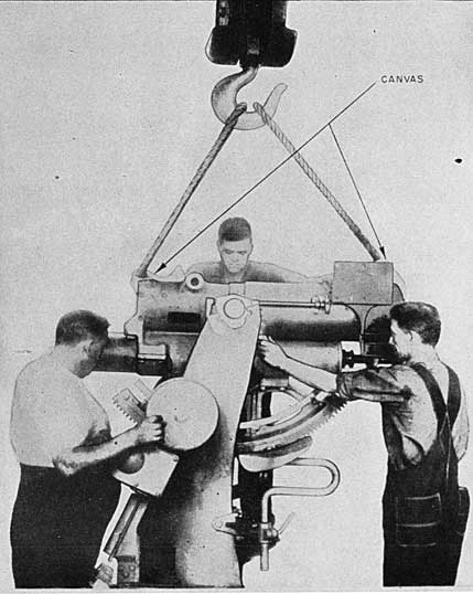
5. Lifting the mount.-When rigging a complete mount assembly for appropriate crane attachment refer to plates 19 and 24 and observe the following instructions.
(a) Deflect sight to limit stop at right end of deflection bar. This is necessary for forward loop of cable sling to clear yoke cross-member.
(b) Elevate gun assemblies to 35° elevation. This will bring the mount into approximate trim.
(c) Pass a canvas covered cable loop under the slide and through the center sector of the elevating arc bracket so that the loop straddles the trunnions and the rear of the loop passes up to bear against the side face of the slide counterweight, as shown on plate 24.
6. Preparation of foundation.-For the details of locating the emplacement aboard ship, the methods of preparing the foundation, and procedure for lifting the mount into position and securing it in place, see instructions chapter V.
Mount Installation Gun and Sight Assemblies
7. Instructions for regunning the mount include disassembly and reassembly procedures
15 Refer cleaning materials, O. P. 1105.
96
for the sight and gun assemblies. These instructions are provided by the following references.
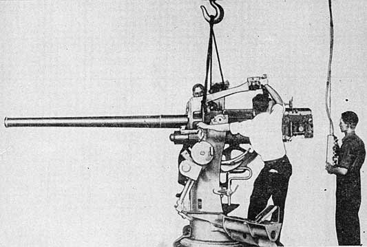
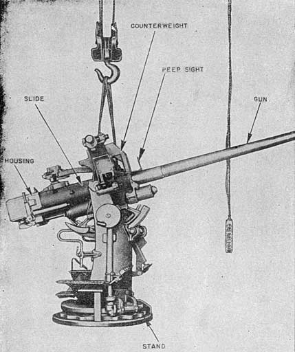
(a) Gun assembly installation.-For details of rigging, lifting and securing the gun assembly in the slide see instructions chapter II; refer to plates 20 and 21.
(b) Sight installation.-For details of rigging, lifting, securing and aligning the sight
assembly on the slide see instructions chapter VI; refer to plate 23.
Trouble Shooting
8. The causes of various installation and emplacement troubles, and the corrective procedure in each instance are outlined in the subparagraphs below (drawings referred to are listed
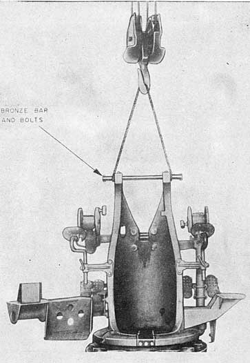
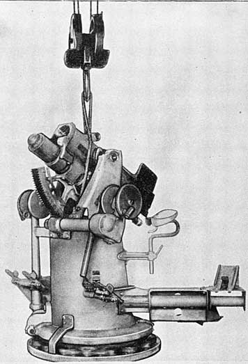
PLATE 17 - 3-INCH MOUNT MARK 22
METHOD OF LIFTING CARRIAGE AND STAND
97
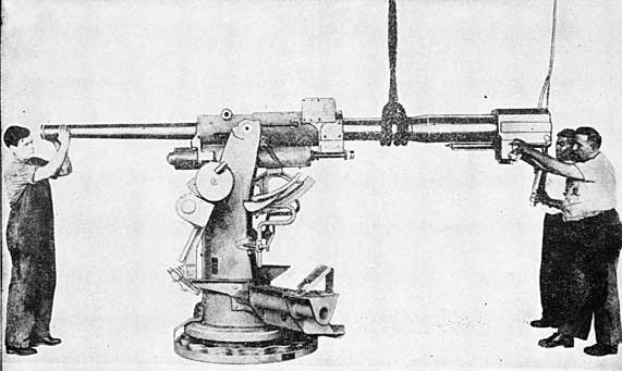
PLATE 18 - 3-INCH MOUNT MARK 22
ASSEMBLY OF SLIDE ON CARRIAGE
98
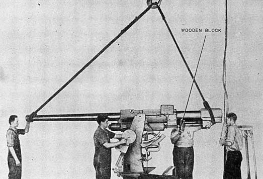
PLATE 19 - 3-INCH MOUNT MARK 22
METHOD OF LIFTING ASSEMBLED SLIDE, CARRIAGE AND STAND
99
PLATE 20 - 3-INCH MOUNT MARK 22
METHOD OF ASSEMBLING GUN ASSEMBLY IN SLIDE - FIRST STAGE
on assembly sketch list 93260 and apply to Mount Mark 22).
(a) Trouble: Mount will not train properly (max. handwheel pull 10 lb. at 4.5-in. radius).
Possible cause
Remedy
(1) Foundation not flat.
Make the foundation flat (0".005 in 45" if wood) (0".7002 in 45" if steel).
(2) Dirt between foundation and stand.
Remove complete mount, clean both stand and foundation.
(3) Frictionless washers, 8-Z-1117-2, rusted.
Install new washers.
(4) Bearing balls, 49850-4, crowding.
Back off adjusting ring, 234749-1, to increase the lift. Under no circumstances should the adjusting ring be backed off more than two inches. Vertical lift should be 0".001 to 0".002, but never greater than 0".004. Stake the adjusting ring in its new position.
Possible cause
Remedy
(5) Improper clearance between stand bushing, 49109-2, and vertical bearing on carriage, 232881.
Disassemble stand, 49109-1, and carriage, 232881, according to instructions in O. P. 811. Scrape stand bushing, 49109-2, to give lateral motion of 0".002 to 0".006.
(6) High spots on training circle, 49110-5.
Blue training circle, train mount back and forth several times over high spots and scrape training circle until high spots are relieved.
(7) Burrs on training circle, 49110-5, or worm 238424-2.
Remove burrs with scraper or fine file.
(8) Rust on training circle, 49110-5.
Remove rust with emery cloth, clean thoroughly and slush with O. S. 1350.
(9) Bent shaft, 498852-4, in training bracket.
Remove shaft, straighten to within drawing tolerances if possible, if not order new shaft.
100
Possible cause
Remedy
(10) Training stop, 232986-1, bears against training indicator scale.
Grind off bottom of train-ing stop for clearance.
(11) Interference between bottom of carriage, 232881, and top of training 49109-4.
Scrape, file or machine off excess metal as indicated by a dimensional check.
(12) Training circle cover and training bracket bind on training circle and stand. Refer sectional view dr. no. 238417.
Grind off excess metal.
(13) Cover plate retaining ring rubs against stand baffle ring.
Scrape to insure clearance.
(14) Handwheel binds on training bracket, 238417.
Scrape handwheel to allow 07002 clearance between handwheel and training bracket when
Possible cause
Remedy
screw, 49885-6, is up tight.
(15) Not enough shims between training bracket, 238418-1, and carriage, 232881.
Add 07002 to 07005 shims and check lost motion between worm and training circle. Lost motion should be equal to or greater than lateral motion. Lateral motion should be 0".002- 0".006.
(16) Training circle screw bolts, 49110-2, not tight allowing training circle to shift.
Tighten and stake the training circle screw bolts.
(17) Key, 49154-2, for locating training bracket, 238418, to carriage, 232881, is too thick causing bracket to be sprung, consequently shaft binds.
Scrape or file key for clearance.
PLATE 21 - 3-INCH MOUNT MARK 22
METHOD OF ASSEMBLING GUN ASSEMBLY IN SLIDE - LAST STAGE
101
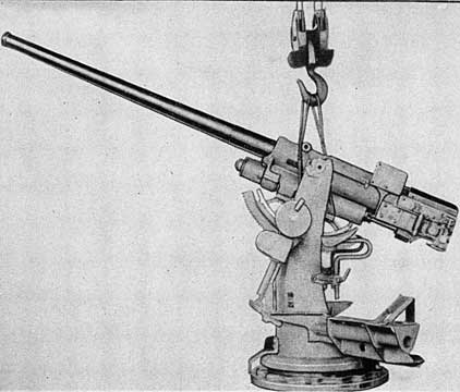
PLATE 22 - 3-INCH MOUNT MARK 22
METHOD OF LIFTING MOUNT, LESS SIGHT ASSEMBLY
Possible cause
Remedy
(18) BallBall races, 40850-2, 3 are not parallel, causing the mount to jam on the tight side.
Place carriage and stand on layoff table and check ball race seats for parallelism (inner and outer ball race seats should be parallel within 0".001). Also check to see that the top and bottom surfaces of ball races are parallel.
(19) Bad threads on adjusting ring, 234749-1, causing ball race seat to cock.
Order new adjusting ring.
(20) Training bracket, 238418-1, not located correctly, causing worm, 238424-2, to ride high or low on training circle, 49110-5.
Locate training bracket so as to center worm in training circle and re-dowel training bracket to carriage with over-size dowel.
(b) Trouble: Mount will not elevate properly (max. handwheel pull 20 lbs. at 4.5-in. radius).
Possible cause
Remedy
(1) Dirt and steel chips between bevel gears, worm and worm wheel, and arc and pinion. Refer drawing number 238417.
Remove all dirt and grease from the affected parts, clean thoroughly and lubricate.
(2 ) Burrs on elevating arc, 243763-1, and pinion, 49158-2.
Scrape or file to remove burrs.
(3) Frictionless washer in elevating bracket rusted. Refer drawing number 238417.
Install new frictionless washer.
(4) Adjusting nut holding elevating worm is too tight. Refer drawing number 238417.
Back off adjusting nut until worm turns free.
102
Possible Cause
Remedy
(5) Taper pin, 12-Z-49-63 in bevel gear, 49158-5, drops out and jams mount in elevation.
Replace taper pin.
(6) Bent elevating shafts. Refer dr. no. 238-417.
Attempt to straighten shaft, if unsuccessful order new one.
(7) Mount not balanced.
Check to see that mount has counterweight, 239742-1.
(8) Wormwheel, 238424-2 not positioned correctly.
Overhaul elevating bracket assembly. A dimensional check of the assembly must be made to determine the reason for improper alignment.
(9) High spot on arc, 243763-1, and pinion 49158-2.
Blue arc, elevate gun up and down, and scrape high spots on arc.
Possible cause
Remedy
(10) Insufficient clearance between carriage vertical trunnion faces, 232881 and slide vertical trunnion faces, 239739.
Make a dimensional check of carriage and slide trunnion faces and scrape to drawing dimensions.
(11) Insufficient clearance between slide trunnion, 239739, and trunnion bushing, 238407-1.
Scrape slide trunnion bushing to allow 0".001 to 0".006 clearance.
(12) Burrs on slide and trunnion carriage faces.
Scrape to remove burrs.
(13) Elevating bracket not shimmed or set properly. Refer dr. no. 238417.
Shim elevating bracket to allow not more than 0".002 clearance between pinion and arc.
(14) Handwheels binding on elevating bracket. Refer dr. no 238417.
Scrape handwheels to allow 0".002 clearance when the securing screw, 49885-6, is tight.
PLATE 23 - 3-INCH MOUNT MARK 22
METHOD OF ASSEM6LING SIGHT ON SLIDE
103
PLATE 24 - 3-INCH MOUNT MARK 22
METHOD OF LIFTING COMPLETE MOUNT
(103)
577305°-44-8
104
Possible cause
Remedy
(15) Elevating arc, 243763-1, rubs against side of carriage.
Grind necessary clearance out of carriage.
(16) Sharp edges at top of teeth on elevating arc, 243763-1, or pinion, 49158-2.
Remove sharp edges by filing or scraping.
(e) Handwheel pulls on the sight are uneven or too high (max. elevating pull 20 lbs. max. azimuth pull 10 lbs.).
(1) Dirt on sight bar and head, 49875-1.
Clean and lubricate according to lubrication chart, 238289.
(2) Elevating and azimuth gear Bracket, 49876-1 not located correctly on dowels.
Loosen 3/4-in. machine bolts securing elevating and azimuth bracket to slide. Shift bracket on dowels taking full advantage of any clearance around the dowels.
(3) Damaged or burred teeth or racks and pinions. Refer dr. no. 49875.
Scrape to remove burrs.
(4) Interference with counterweight at high elevation and maximum deflection.
File, grind or chip necessary clearance out of counterweight.
(5) Rust on working surfaces.
Remove rust with very fine emery cloth and lubricate.
(6) Dirt and burrs on working surfaces of rocker, 236431, and yoke, 236473.
Clean thoroughly, remove burrs by scraping or filing.
(7) Badly bent or damaged shims between elevating and azimuth gear bracket, 49876-1 and slide 239738.
Install new shims.
(8) Interference between clamping discs and drum covers, 238477.
Scrape clamping disc to fit drum cover.
(9) Bent handwheel shafts. Refer dr. no. 238477.
Attempt to straighten. If unsuccessful order new shaft.
(10) Poor fit between elevating and azimuth gear bracket, 49876-1, and sight bar, 49875-1 so that tightening the two rear bracket bolts will seize the bar.
Scrape elevation and azimuth gear bracket where sight bar fits. Blue sight bar, run up and down in bracket and scrape high spots on the bracket.
Possible cause
Remedy
(11) Yoke, 326473, twisted in handling.
Attempt to straighten, if unsuccessful, order new yoke.
(12) Bent sight bar, 49875-1.
Attempt to straighten, if unsuccessful order new sight bar.
9. Recoil system check.-Check recoil cylinder for correct level hydraulic recoil fluid. Refer to filling instructions chapter III.
10. Counterrecoil tests.-The gun and mount should be kicked just prior to or after installation aboard ship. The kicking can be done with either a kicking machine, similar to drawing number 234192, or a chain fall and pelican hook. In either case the gun and housing are brought back 11.5 inches out of battery and released suddenly. The gun and mount should be kicked in both single fire and semiautomatic breech operation so as to insure that the complete mount will operate properly when fired.
11. The gun mount may be kicked with a chain fall and pelican hook in the following manner:
(a) Attach the mount securely to the deck.
(b) Attach the chain fall securely to the deck.
(c) Pass a rope sling beneath the housing and around the piston rod.
(d) Elevate and train the mount so that the center line of the bore of the gun passes through the point on the deck where the chain fall is attached.
(e) Attach the chain fall to the rope sling by means of a pelican hook.
(f) Pull the gun and housing back 11.5 inches with the chain fall.
(g) Release the gun and housing by opening the pelican hook.
(h) Gun should go back to battery smoothly, without bumping and without galling any of the operating parts.
12. Painting.-The complete mount should be painted as soon after installation as possible. The priming coat should be touched up immediately after installation. If the carriage cover plate has been removed to make the electrical and communication cable connections, the mating surfaces of the carriage and cover plate should be cleaned and repainted and the cover secured in place while paint is still fresh, every effort being made to secure a watertight seal.
105
APPENDIX I
INDEX OF ASSEMBLIES
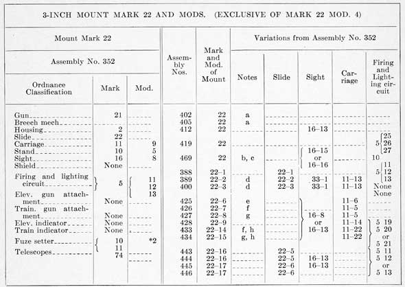
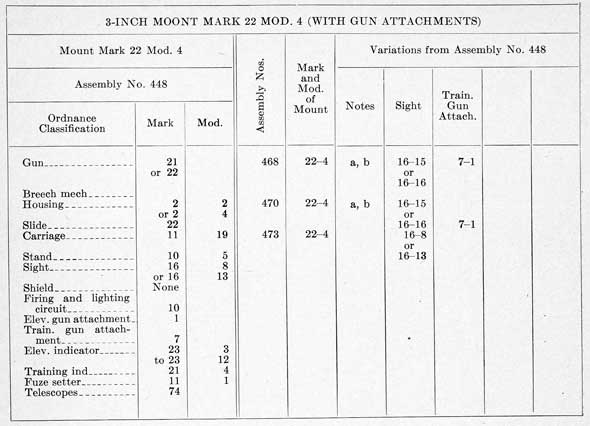
This index of 3-inch Gun Mount Mark 20 modifications, Marks 21 and 22 with their modifications, is a tabulation of all mount assemblies described in Ordnance Pamphlet No. 811. It is an index of 3-inch assembly numbers and of lists of assemblies comprising each modification of the three Marks covered in the title.
Index of assembly numbers
Assembly numbers
Mount Mark and Mod.
Sketch list No.
Assembly numbers
Mount Mark and Mod.
Sketch list No
335
20-1
62495
421
21-1
106232
338
20-1
62823
425
22-6
106342
339
20-2
92395
426
22-7
106426
340
20-3
92396
427
22-8
106427
342
21
92433
428
22-9
106428
352
22
93260
433
22-14
106433
360
20-3
94370
434
22-15
106434
362
20-4
94511
440
20-11
106440
388
22-1
94833
441
20-11
106441
389
22-2
94834
443
22-16
106786
395
20-1
102800
444
22-16
106790
400
22-3
92946
445
22-17
106799
402
22
103127
446
22-17
106800
403
20-5
103129
448
22-4
107085
405
22
103139
468
22-4
108309
407
21-1
103272
469
22
108311
412
22
103294
470
22-4
108312
419
22
106229
473
22-4
108327
420
21
103202
474
20-3
108332
106
3-INCH MOUNT MARK 20 AND MODS.
Mount Mark 20 Mod. 1
Assembly Nos.
Mark and Mod. of Mount
Variations from Assembly No. 335
Assembly No. 335
Notes
Gun
Firing and Lighting Circuit
Carriage
Stand
Ordnance Classification
Mark
Mount
Gun
20
--
338
20-1
d
20-1
--
--
--
Breech Mech
5
11
395
20-1
a
--
--
--
--
Housing
--
--
339
20-2
--
--
--
11-5
10-6
Slide
20
--
340
20-3
--
--
--
11-5
10-7
Carriage
11
6
360
20-3
--
--
--
11-5
10-7
Stand
10
5
474
20-3
--
20-1
--
11-5
10-7
Sight
16
5
362
20-4
b
20-1
None
11-12
--
Shield
None
--
403
20-5
c
--
--
11-14
--
Firing and Lighting Circuit
5
5,6 or 7
440
20-11
c, d
--
See Note c
11-22
10-6
441
20-12
c, d
--
See Note c
11-22
10-7
Elev. gun attachment
None
--
--
--
--
--
--
--
--
Train. gun attachment
None
--
--
--
--
--
--
--
--
Elev. indicator
None
--
--
--
--
--
--
--
--
Train. indicator
None
--
--
--
--
--
--
--
--
Fuze setter
10 or 12
--
--
--
--
--
--
--
--
Telescopes
74
--
--
--
--
--
--
--
--
NOTES
a. Fuze Setter Mark 10.
b. Breech Mechanism Mark 5 Mod. 12. Slide Mark 20 Mod. 1. Shield Mark 14. Sight. Mark 33.
c. Fuse Setter Mark 11 Mod 2. Firing and Lighting Circuit Mark 5 Mods 16, 17 or 18.
d. Sight Mark 16 Mod. 5 or Mod 10.
3-INCH MOUNT MARK 21 AND MOD.
Mount Mark 21
Assembly Nos.
Mark and Mod. of Mount
Variations from Assembly No. 342
Assembly No. 342
Notes
Sight
Slide
Ordnance Classification
Mark
Mount
Gun
21
1
--
--
--
--
--
--
--
Breech mech
--
--
420
21
--
16-12
--
--
--
Housing
2
1
407
21-1
--
--
21-1
--
--
Slide
21
--
421
21-1
--
16-12
21-1
--
--
Carriage
11
8
--
--
--
--
--
--
--
Stand
10
8
--
--
--
--
--
--
--
Sight
16
7
--
--
--
--
--
--
--
Shield
None
--
--
--
--
--
--
--
--
Firing and lighting circuit
None
--
--
--
--
--
--
--
--
Elev. gun attachment
None
--
--
--
--
--
--
--
--
Train, gun attachment
None
--
--
--
--
--
--
--
--
Elev. indicator
None
--
--
--
--
--
--
--
--
Train. indicator
None
--
--
--
--
--
--
--
--
Fuze setter
None
--
--
--
--
--
--
--
--
Telescopes
78
--
--
--
--
--
--
--
--
Muzzle cover
2
--
--
--
--
--
--
--
--
107
*Fuze Setter Mark 11 Mod. 1 installed on some mounts in anticipation of director gear installation.
NOTES
a. Proving Ground Mount
b. Fuze Setter Mark 11 Mod. 1
c. Sight Angle Receiver Mark 1; Sight Deflection Receiver Mark 1 Mod. 1.
d. Shield Mark 14; Fuze Setter not included.
e. Gun Mark 22 or Mark 22 Mod. 2; Housing Mark 2 Mod. 2 or Mod. 4.
f. Stand Mark 10 Mod. 6:
g. Stand Mark 10 Mod. 7.
h. Gun Mark 21 or Mark 22; Housing Mark 2 or Mark 2 Mod. 2.
108
NOTES
a. Housing Mark 2 or Mark 2 Mod. 2.
b. Sight Angle Receiver Mark 1. Sight Deflection Receiver Mark 1 Mod. 1.
RESTRICTED
OP 811 (1st. Rev) Change I
APPENDIX II
3-inch Mounts Mark 22 Mods 4 and 20
QUICK FIRING MECHANISM
General Description
1. Elements of the gun assemblies and slide, as installed on3-inch Mounts Mark 22 Mods. 4 and 20, and other modifications equipped with gun attachments, are being modified as per Ordalt No. 1912 to provide a quick firing mechanism with firing key or root treadle control. Instantaneous firing is accomplished upon closure of the breechblock by maintaining the solenoid energized or the foot treadle depressed. Delayed firing is accomplished by preloading a spring attached to the trigger pull bar, and then releasing by foot treadle or firing key controlled solenoid.
2. Mounts affected. - The above installation is to be made on Mounts Mark 22 Mods. 4 and 20, and other modifications equipped with gun attachments. Mounts Mark 22 Mod. 4 equipped with director control are to be likewise equipped, as well as other specific mounts upon request of Commanding Officer and Bureau of Ordnance approval. Mounts modified in accord with the Ordalt are redesignated as follows:- 3-inch Mount Mark 22 Mod. 4 becomes Mod. 21 and 3-inch Mount Mark 22 Mod. 20 becomes Mod. 22.
Detail Description
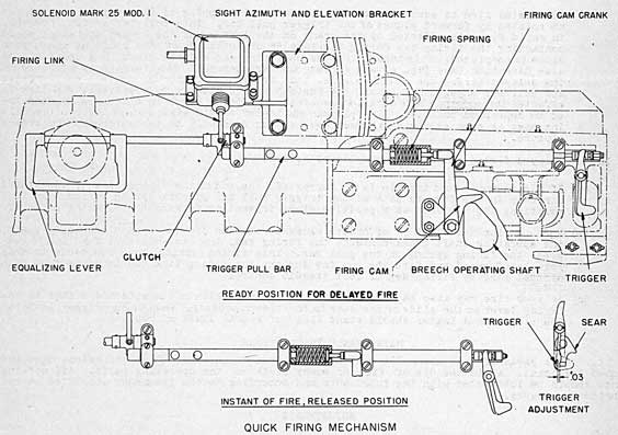
3. Components. - The modified firing mechanism consists of the following elements, arranged as shown in figure A.
Gun Firing Solenoid Mark 25 Mod. 1
Solenoid support bracket
Firing link and clutch
Trigger pull bar and extension
Firing cam
Firing cam crank
Firing cam support bracket
Delayed firing spring assembly
Snap Switch Mark 11
Other elements of the firing mechanism are modified from previous design.
FIG. A - FIRING MECHANISM ARRANGEMENT
4. Solenoid. - Solenoid Mark 25 Mod. 1 is an element of 3-inch Firing and Lighting circuit Mark 5 or Mark 10 and Mods. It is the gun firing actuating device in both pointer firing key or remote control firing action. It is mounted on a support bracket secured to the sight azimuth and elevation bracket and effects plunger contact with the solenoid release lever which is pinned to the equalizing lever rod.
5. Firing link. - This is the element actuated by the solenoid which functions as a forward stop for the trigger pull bar in delayed firing action, which action loads the pull bar for delayed firing thrust. As the lever is secured to the equalizing lever rod by the clutch collar it also functions in foot treadle control.
ch1-2
6. Trigger pull bar. -This is the longitudinal sliding element, mounted in guides on the slide cam plate, which functions to store spring energy for delayed firing action when initiated by the release lever. In quick firing action the pull bar functions to transmit firing action from breech operating shaft crank through firing cam to trigger. This element is limited in its slide movement by the forward guide retainer.
7. Firing cam assembly. - This assembly, comprised of the support bracket, firing cam, and cam crank, is secured to the slide cam plate and constitutes the initiating mechanism for quick firing action. The cam and crank are pivoted in the support bracket and rotate under impact from the crank on the breech operating shaft.
Modifications of Original Firing Assembly
8. The cam plate retractor handle is removed from the slide can plate and the cam plate
is modified for mounting the firing cam support bracket. For mounts equipped with Solenoid Mark 14, the solenoid is removed together with its mounting bracket from the slide cam plate and the upper part of the solenoid contact lever on the trigger is cut away. For mounts equipped with solenoid Mark 5 and Mods, the solenoid is removed and the solenoid contact pin on the trigger is cut away. The sight azimuth and elevation bracket is drilled to mount the solenoid support bracket, and the equalizing lever torque rod is modified to accommodate the firing crank and clutch collar. The trigger pull bar is drilled for assembly of the bar extension and the firing spring assembly. 'Slides modified in accord with the Ordalt are redesignated as follows: 3-inch Slide Mark 22 becomes Mod. 8, and 3-inch Slide Mark 22 Mod. 6 becomes Mod. 9.
OPERATION
9. As described in O.P. 811 first revision, chapter II, paragraphs 28 and 29, the breechblock is raised into the closed position as the operating shaft is rotated by action of the operating spring. This shaft rotation in its final phase functions to operate the quick firing mechanism in the following manner:
(a) To initiate rapid fire, in pointer control, the pointer either closes- firing key on handwheel or depresses foot treadle. If initiated by firing key the solenoid plunger snaps forward contacting the firing link on the rear of the equalizing lever torque rod, and swings the lower toe of the link clear of the forward end of the trigger pull bar.' If, initiated by foot treadle, the same action occurs through conventional bell crank and torque rod linkage. Thus the trigger pull bar is free to ride forward in its cam plate guides.
(b) Percussion fire is accomplished by conventional tripping of the sear by the trigger as rotated by forward plunge of the trigger pull bar. This pull bar action, however, in rapid fire, is effected by the crank on the left end of the breech operating shaft contacting the firing cam during the last 5° of rotation of the shaft as the breech close is completed. This impact rotates the firing cam and cam crank in a counter-clockwise direction (see fig. A) and forces the trigger pull bar forward by pressure on the delayed firing spring and housing, thus tripping sear through conventional trigger and pull bar engagement. Thus, the instant breech closure is completed, gun fire is effected through the above detailed mechanism, if firing key or foot treadle is maintained in depressed position. The plugman and loader should always stand clear of recoiling mass as soon as round is rammed home as gun fire will be instantaneous with breech closure.
10. Delayed firing action is accomplished as follows:-
(a) If firing key or foot treadle is not depressed, the toe of the firing link is positioned directly in the forward path of the trigger pull bar by coil spring action. In this position, the toe acts as a positive stop, preventing forward travel of the pull bar.
(b) When, during the final 5° of breech closure rotation of the breech operating shaft, the operating shaft crank contacts the firing cam, the cam and crank function to compress the firing spring on the pull bar. This firing spring then functions to snap pull bar forward and fire the gun the instant the firing link toe is swung from path of pull bar, by firing key or foot treadle control.
(c) Delayed fire may also be accomplished by lanyard, which may be attached either to the firing lever on the slide or the sear in the breech housing. When using trigger lanyard, the plugman and loader should stand clear of recoil limit of housing.
MAINTENANCE INSTRUCTIONS
11. All parts of this mechanism must be maintained clean, free from corrosion, dirt and gummed lubricant. Avoid the use of file or emery cloth on the operating parts. All working parts should be lubricated with the lubricants and according to the frequency specified on the lubrication charts.
ADJUSTMENTS
12. Firing spring. - At assembly the firing spring plunger which connects the firing cam crank with the trigger pull bar should be adjusted and locked with jam nut so that the spring length at maximum compression will be 0.30-inch greater than the solid spring length.
13. Trigger pull bar link. - This adjusting screw, see figure A, should be adjusted so that the trigger pull bar in the delayed firing position with breech closed maintains a clearance of 0.30-inch between the trigger and the sear nib.
14. Firing link clutch. - At initial assembly of clutch on equalizing lever torque rod, the clutch is positioned and pin secured to rod so that a clearance of approximately .03-inch is afforded between the end of the trigger pull bar and the firing link toe.
109
DISTRIBUTION
Requests for copies of OP 811 (1st Revision) should be addressed to the nearest BuOrd Publications Distribution Center:
Commandant and Superintendent,
U. S. Naval Gun Factory, Navy Yard,
Washington 25, D. C.
(Attn: OrdPubSubcen)
Commandant,
Navy Yard,
Male Island, Calif. (Attn: OrdPubSubcen)
Commander. Service Force, Seventh Fleet,
Ordnance Publications Subcenter,
c/o Fleet Post Office,
San Francisco, Calif.
Officer in Charge,
Ordnance Publications Subcenter, Naval Supply Depot,
Pearl Harbor, T. H.
DISTRIBUTION:
Standard Navy Distribution List No. 18
2 Copies each unless otherwise noted.
1. a-e, g, k-u, w, x, z-gg, u, ss, tt, zz; 2. f (DE Divs only), g-i, m-p, s, t (Glenview only), v, x, as (LST Flotillas only); 2. (1 copy), a (BatDiv 5), d (CruDiv 1, 2, 3, only), e; B3. (5 copies), LIONS, CUBS, ACORNS; 4.*; 5. b (Alusna, London only), 6. a-p; 7. f-h, k, x; 7. (5 copies), b, c, j, 1; 7. (10 copies), a; 8. h (NOL and No. Beach only), j, n (SPECIAL LIST K, L, V, AA), n (3), q, z; 8. (5 copies), n (SPECIAL LISTS) (Bainbridge, Farragut, Great Lakes, Newport, Sampson, San Diego only), x; 8. (10 copies), r; 8. (25 copies), n (SPECIAL LIST 0) (OinC, San Diego & Washington, D. C. only); 10. t; 10. (10 copies), s (except San Francisco, New York and New Orleans); 10. (25 copies), nn; 10. (30 copies), s (New Orleans only); 10. (50 copies), s (New York, San Francisco only); 11. a (CNO, ComdtMarCorps); 11. (1 copy), a (SecNav only);12. 14. a; OCO, War Dept., (25 copies), OinC NavTraSch, DesCort, Beloit, Wis.
* Applicable Ships.
U. S. GOVERNMENT PRINTING OFFICE 1944
Lubrication Charts
DRAWING No 233389
3 in Mount Mk 20, 50 Cal. A.A. Pedestal Type, Open
Plan and Rear Lubrication Chart
SHEET 1 OF 2
577305 O - 44 (Inside back cover) No. 1
DRAWING No 233389
3 in Mount Mk 20, 50 Cal. A.A. Pedestal Type, Open
Right and Left Sides Lubrication Chart
SHEET 2 OF 2
577305 0 - 44 (Inside back cover) No. 2
DRAWING No 241154
3 in Mount Mk 20 Mod. 4, 50 Cal. A.A. Pedestal Type, Shielded
Plan and Rear Lubrication Chart
SHEET 1 OF 2
577305 O - 4 (Inside back cover) No. 3
DRAWING No 241154
3 in Mount Mk 20 Mod. 4, 50 Cal. A.A. Pedestal Type, Shielded
Right and Left Sides Lubrication Chart
SHEET 2 OF 2.
577305 0 - 44 (Inside back cover) No 4
DRAWING No 237386
3 in Mount Mk 21, 50 Cal. A.A. Pedestal Type, Wet
Plan and Rear Lubrication Chart
SHEET 1 OF 2
577305 O - 44 (Inside back cover) No. 5
DRAWING No 237386
3 in Mount Mk 21, 50 Cal. A.A. Pedestal Type, Wet
Right and Left Sides Lubrication Chart
SHEET 2 OF 2
577305 O - 44 (Inside back cover) No. 6
DRAWING No 238289
3 in Mount Mk 22, 50 Cal. A.A. Pedestal Type, Open
Plan and Rear Lubrication Chart
SHEET 1 OF 2
577305 O - 44 (Inside back cover) No. 7
Drawing No 238289
3 in Mount Mk 22, 50 Cal. A.A. Pedestal Type, Open
Right and Left Sides Lubrication Chart
577305 0 - 44 Inside back cover) No. 8
Drawing No 241969
3 in Mount Mk 22, Mods. 2 and 3, 50 Cal. A.A. Pedestal Type, Shielded
Plan and Rear Lubrication Chart
SHEET 1 of 1
577305 O - 44 (Inside back cover) No. 9
Drawing No 241969
3 in Mount Mk 22, Mods. 2 and 3, 50 Cal. A.A. Pedestal Type, Shielded
Right and Left Sides, Lubrication Chart
SHEET 1 OF 1
577305 O - 44 (Inside back cover) No. 10
Drawing No 248722
3 in Mount Mk 22, Mods. 4, 50 Cal. A.A. Pedestal Type, Open
Plan and Rear Lubrication Chart
577305 O - 44 (Inside back cover) No. 11
Drawing No 248723
3 in Mount Mk 22, Mods. 4, 50 Cal. A.A. Pedestal Type, Open
Right and Left Sides, Lubrication Chart
577305 O - 44 (Inside back cover) No. 12