Constant effort and research are devoted to the
development and improvement of naval sonar
and associated equipment. As more efficient
equipment is perfected old equipment is replaced
as rapidly as possible consistent with production
and money available. There is an unavoidable
time lag between the development and installation
of new equipment in ships of the fleet and inclusion of such equipment in a publication such as
this. At the time you use this book, some equipment discussed in this and succeeding chapters
may not be the equipment currently being used
in the fleet. However in most cases circuits and
operating principles will be similar to those found
in current equipment. Equipment manuals for
specific equipment should be studied thoroughly
by personnel responsible for repair maintenance
and operation of that equipment.
MODEL QGB
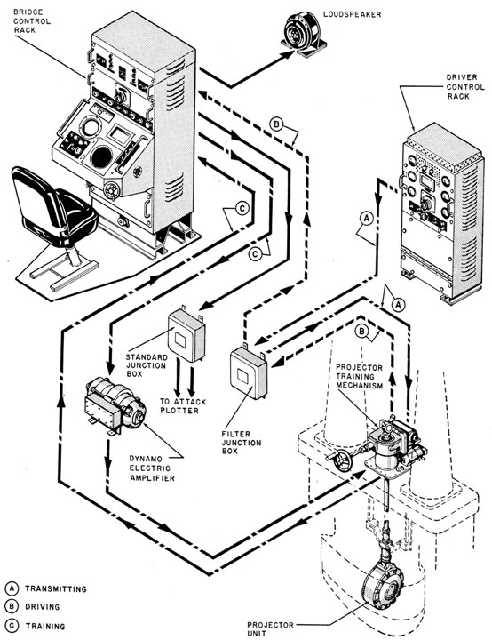
The model QGB sonar equipment, shown in
figure 6-1, is typical of modern searchlight equipment. This type of equipment is designed for
installation aboard destroyer escorts and destroyers. The QGB consists of a transmitter, a receiver, an indicating range recorder, a bearing
deviation indicator, and a transducer with an
associated hoist-train mechanism.
The system operates at a frequency determined
by the resonant frequency of the magnetostriction
transducer. Available frequencies are 20, 22, 23,
and 26 kc. The transmitter and receiver both
cover the frequency range of from 17 to 26 kc.
To change the operating frequency of the system,
and still have it operate efficiently, the transducer must be changed. Because magnetostriction transducers have sharply resonant characteristics, the system must be adjusted to the resonant
frequency of the transducer.
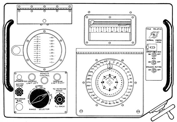
The receiver, bearing-deviation indicator, indicating range recorder, range indicator, remote
training control, and the keying control unit are
contained in a console, which is the sonarman's
operating station. The indicator panel of the
console is shown in figure 6-2. This console is
housed in the sonar control room. The transmitter and its power supply are contained in a
cabinet in the sonar equipment room. The hoist-train mechanism is located in the lower sound
room.
Receivers and transmitters will be discussed in
chapters 7 and 8, respectively.
The transducer, with its training and hoisting
mechanism, generally is installed so that the unit
is parallel to the fore-and-aft axis of the ship.
The transducer, which can be rotated through a
maximum of about 840°-2 1/3 revolutions-operates over the entire port and starboard sectors of
the vessel.
The transducer itself is mounted in a sea chest
and the transducer and its hoisting units are
raised and lowered inside this chest. When in
the raised position, the sound dome seals off the
sea chest so that water cannot enter the ship if
the top of the chest were removed. Sealing off
the chest in this manner permits installation,
removal and servicing of the transducer and its
training mechanism while the ship is at sea or in
port. All other units of the system are accessible
from the interior of the ship.
The bearing scale on the transducer shaft in
the lower sound room is adjusted to read zero when
the transducer is directed dead ahead. The
bearing is remotely repeated at the operating
position in the sonar control room by a synchro
repeater system. The repeater on the operating
console indicates either true or relative bearings.
The transducer is trained by rotating a handwheel on the console, geared to a control transformer. The output of this control transformer
is the error signal for the training control amplifier
that controls the amplidyne generator.
123
Figure 6-1. -Pictorial diagram of the QGB system.
124
After the maintenance-of-true-bearing (MTB)
feature is switched on any change in the ship's
heading causes the transducer to rotate by the
same amount but in the opposite direction. Thus,
the transducer remains on the same true bearing
regardless of changes in the ship's heading.
Keying of the equipment can be controlled by
any one of the four means-(1) the range recorder
located in the console of the equipment, (2) an
external tactical range recorder, (3) a hand key
on the console, or (4) a multivibrator that is a
part of the keying unit.
The keying intervals are arranged and controlled
as follows. When keying is controlled by the
sound-range recorder, two scales are available-one at 1,500 yards and the other at 3,750 yards.
To conserve recorder paper when there is no
target, a multivibrator takes control. The multi-vibrator has two time rates-one at a scale of
3,000 yards and the other at a scale of 5,000 yards.
During search operations one of the last two
scales is selected depending upon sound conditions.
The keying interval and the conditions of
manual keying or listening are selected by a rotary
switch on the console.
The cycle of operation of the QGB is as follows:
(1) A keying signal is delivered to the keying unit
which energizes the keying relay. (2) The relay
transfers the transducer from the receiver input
to the transmitter output. (3) The transmitter
impresses an r-f voltage of the correct frequency
across the transducer at the proper energy level.
(4) The transducer converts this energy into sound
power, and emits it in a narrow beam along the
bearing to which the transducer is trained.
(5) Immediately after the keying period the relay
restores the transducer connections to the receiver input. (6) Any sound energy that is returned to the transducer is converted into electric
energy and applied to the receiver input.
Figure 6-2. -Indicator console of the QGB system.
239276°-53-9
125
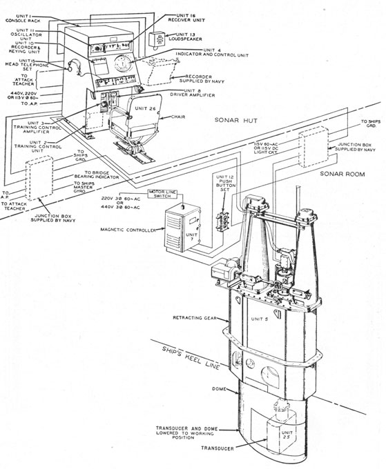
Figure 6-3. -Pictorial diagram of the QJB system.
126
In the QGB, the receiver output is supplied to
a loudspeaker or headphones to allow the operator
to identify the signals. This signal voltage may
also be used to mark the paper in the recorder
and make a permanent record on the chart. A
third use of the signal is to deflect the beam of
the bearing deviation indicator (BDI).
MODEL QJB
The model QJB, shown in figure 6-3, is a searchlight sonar equipment also intended for installation in destroyers and destroyer escort vessels.
This equipment is smaller than the QGB, and all
its electronic units are housed in a single console.
The QJB transmitter is much smaller than the
QGB transmitter, because of the lower power
requirements of the QJB. Although the transmitted power is less, the resultant echoes are
equal to those of the QGB due to the higher sensitivity of the crystal transducer of the QJB.
The transmitter is mounted in the lower right section of the console. The other units in this console are the receiver, keying unit, bearing deviation indicator, indicating range recorder, remote
training control, and power supplies.
The receiver is of the sum and difference type
and has both time-varied-gain (TVG) and reverberation-controlled-gain (RCG) features.
The QJB utilizes the unicontrol-oscillator system for tuning the receiver and transmitter. The
operating frequency need not be tuned carefully
to the frequency of the crystal transducer because
the transducer has a rather flat resonance curve-about 6 kc wide.
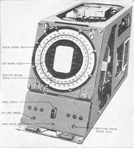
The chief difference in the appearance of the
QJB console as compared with the QGB is the
manner in which the BDI cathode-ray tube is
mounted. The QJB mounting is shown in figure
6-4. The tube is located in the center of the
bearing circle so that the operator does not have
to shift his eyes away from the bezel indicating
the transducer bearing when he wishes to see the
BDI indications. To mount the BDI cathode-ray tube in the center of the bearing indicator-which consists of a true-bearing circle and a bezel
ring that indicates the transducer bearing-a
complicated mechanical system is required.
The keying-control unit and indicating range
recorder are conventional.
Figure 6-4. -BDI and remote bearing indicator of the QJB
console.
The transducer is made up of ADP crystals
mounted on a steel plate. These crystals project
perpendicularly from it a distance equal to one-quarter wavelength of sound in the crystal medium. Opposite the crystals on the reverse side of
the mounting plate are steel rods extending a distance equal to one-quarter wavelength of sound
in the steel medium. These steel rods are longer
than the crystal units because the velocity of
sound is greater in steel than in crystal. This
system of mounting the crystals with the resonating rods results in greater power output than if
the crystals were used alone. It has the disadvantage of making the transducer frequency
sensitive.
This combination forms a half-wave system
rigidly mounted in the center. In this type of
system the mounting plate is stationary, and the
crystals vibrate in a direction perpendicular to the
plane of the mounting plate. The crystals are
connected so that they all vibrate in time
phase-all crystal surfaces move in the same direct ion at the same time. The results of this
arrangement approach the theoretical results of
the piston type of vibrating source.
127
The crystal array is housed inside a rubber sound
window. The space inside the sound window that
is not occupied by crystals is filled with castor oil
that has been treated to remove all air and moisture. This castor oil protects the crystals from
damage by moisture, because it excludes water.
The only other unit of this equipment that is not
located in the console is the retracting gear, which
is in the hull of the ship near the keel. This retracting gear is similar to that of the QGB equipment. However, it is slightly smaller because the
QJB transducer is smaller.
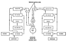
MODEL QGA
Model QGA (figure 6-5) is another searchlight
sonar system designed for installation on destroyers. The system has two complete sonar equipments that are practically identical. One operates
on a frequency of 14 kc; the other, on a frequency
of 30 kc. The 30-kc transducer can be tilted
downward from an angle of 0° to an angle of 45°
below the deck. This feature is of value when the
sonar vessel is approaching a deep target.
The QGA consoles are similar to the QGB console. They are installed side by side in the sonar
control room. The two equipments of the QGA
are capable of independent operation, or they may
be slaved by a control on the 14-kc console. An
Figure 6-5. -Block diagram of the QGA system.
external tactical recorder can be used to control the
transmission of either equipment or both of them.
The receiving system for each console consists of
an audio receiver and a BDI receiver. The transmitters are conventional r-f amplifiers. A unicontrol-oscillator system tunes the receivers and transmitter of each unit.
The magnetostriction transducers are mounted
on concentric shafts that are hoisted and lowered
together. The 30-kc transducer is smaller because
of its higher frequency. It is mounted over the
14-kc transducer. The training mechanisms are
arranged so that the transducers can be trained
independently of each other.
Scanning Sonar Equipment
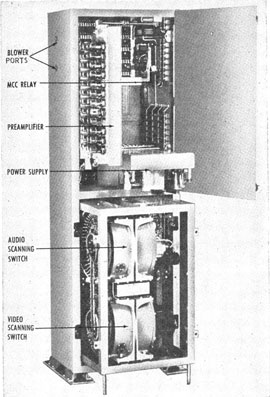
MODEL QHB-a
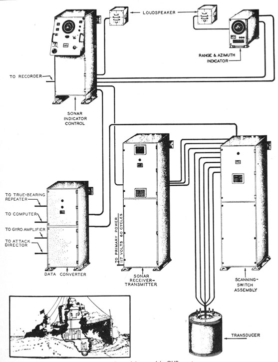
The model QHB-a scanning sonar equipment
(figure 6-6) is an ultrasonic, magnetostrictive,
echo-ranging-listening equipment that provides a
video presentation of acoustic reception from all
directions and an audio presentation of reception
on any selected bearing.
In the echo-ranging condition, the QHB-a transmits a pulse of sound power in all directions, and
then scans or samples all echoes so as to produce on
the screens of associated cathode-ray tubes a plan-position indication of all echoes received. Simultaneously, the audio-channel sensitivity pattern
may be trained in any desired direction for aural
recognition of the characteristics of any of the
echoes, as well as for determination of the range by
means of a range recorder.
In the listening condition, automatic transmission is omitted. However, the video channel is
still alert in all directions. It scans 26-kc ultrasonic frequency noise and produces radial patterns
on the screens of the cathode-ray tubes, from which
the true bearing of any noise source can be obtained.
Simultaneously, the audio-channel sensitivity pattern may be trained on any noise source for determination of its character.
System Line-Up
The system employs a single transducer for both
transmission and reception. It contains 48 electrically independent hydrophones, which are arranged symmetrically along the periphery of a
nontrainable cylinder. During the transmission
pulse of 35 milliseconds these hydrophones are
connected in parallel by the receive-transmit
switching relay so that the acoustic power is
transmitted simultaneously in all azimuth directions. Immediately after the transmission pulse
128
Figure 6-6. -Pictorial diagram of the QHB-a system.
129
the receive-transmit switching relay returns the
circuit to normal so that the hydrophones are
again independent. Any reflected acoustic intelligence is incident only on those hydrophones
that face its path. The output of each of these
hydrophones is connected through their individual
preamplifiers to corresponding stator segments on
both the audio and the video scanning switches.
The scanning switches do not effect a direct contact but utilize a capacitive connection. The
stator plates connect to their corresponding hydrophone units, and the rotor plates-18 in
number-connect to a lag line to form the acoustic
beam. Scanning switches are needed to interpolate bearings; otherwise the bearing could be
obtained only in steps of 7.5° and the accuracy
of the equipment would be impaired.
The video scanning switch is driven at a continuous rate of 1,750 rpm. Geared at a 1-to-1
ratio with this switch is a control transformer
that positions the electron beam of the
cathode-ray tube so that it remains in synchronism with
the true bearing of the scanning switch.
The rotor of this control transformer is excited
by a d-c voltage that is varied linearly with time
to produce a slowly expanding spiral sweep. The
picture of the cathode-ray tube therefore indicates
plan position with the ship at the center. The
audio switch is identical to the video switch but
is not continuously rotated. The rotor of the
audio switch is positioned by a servo system that
is controlled from the console. This servo system
drives another control transformer, which feeds
the bearing information back to the cursor line.
The cursor line appears on the screen of the
cathode-ray tube during the transmission period
and indicates the true bearing to which the audio
channel is trained. Two scanning switches are
needed because the video switch is rotated so
rapidly that audio signals from it occupy too
small a time duration to be heard. The inputs
to the scanning switches are parallel, but their
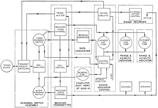
Figure 6-7. -Block diagram of the QHB-a system.
130
outputs are separate and each supplies a receiver.
The circuits just discussed are called the directional-sensitivity circuits.
The transmitter is a conventional pulse-type
amplifier.
A block diagram, figure 6-7, illustrates the
over-all operation of the QHB-a equipment.
Transmission is initiated by a keying pulse, which
originates in the keying-pulse generator circuit of
the sonar indicator control and which either functions automatically or is triggered by a range
recorder. This pulse operates the relay for the
transmit-receive switching and produces the transmitted power at a frequency derived from the
unicontrol-oscillator system of the receiver. This
transmitting electric power is transformed into
acoustic power by the transducer and transmitted
simultaneously in all directions. At the end of
the transmission the keying relay restores the
circuits to the condition for receiving, and the
transducer then acts as a hydrophone and produces electric signals from acoustic reflections or
noise sources.
The video scanning switch, rotating continuously at 1,750 rpm, produces a signal voltage
whenever its acoustic beam sweeps past an echo
signal. This voltage is then delivered to the
video channel of the receiver, a conventional
superheterodyne, the rectified output of which
supplies brightening signals for the grids of
cathode-ray tubes. The beam deflection in these
tubes is synchronized with the video scanning
switch so that the brightening occurs at the correct
indicator bearing. Approximate range is shown
by causing the axial deflection of the beam to increase at an appropriate rate with respect to time.
This procedure produces a slowly expanding
spiral sweep.
The audio scanning switch, which can be positioned by the training control, receives echo
signals from a particular bearing and delivers
them to the audio channel of the receiver. This
channel also is a conventional superheterodyne
with a beat-frequency oscillator for producing
audio notes from the ultrasonic echo signals. The
output of this channel supplies echo signals to the
loudspeakers and the range recorder.
In addition to the echo scanning, the video
presentation includes (1) a radial solid line, or
bearing cursor, and (2) a radial dotted line, which
indicates direction of the ship's stern. The
bearing cursor appears automatically on the
screen of the cathode-ray tubes at a bearing that
corresponds to the direction in which the acoustic
beam of the audio scanning switch is trained.
Cursor time is confined normally to a portion of
the transmission interval but may be extended
when the OKA-1 sound range recorder is in
operation. When slewing, the bearing cursor
automatically appears continuously. The stern-line indicator appears only during the sweep
interval and progresses with the sweep from a
small arbitrary range to the maximum range
use.
Description of Components
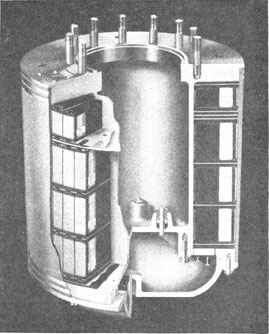
Transducer. -The transducer is the underwater
element that performs the fundamental function
of reciprocal conversion of acoustic energy into
electric energy. It is a simple cylinder, as shown
in figure 6-8.
The construction and harnessing of the units
are such that the mechanical Q is approximately
12. When the transducer is connected to the
system load, the effective Q is reduced to approximately
Figure 6-8. -Cut-away view of the QHB-a transducer.
131
8 ½, thus providing a 3-kc operating frequency band.
The transducer is composed of 48 transducer
units mounted radially in the transducer. A
cut-away view of a single unit is shown in figure
6-9.
Directly above the array of 48 transducer units
is a similar ring of 48 smaller units, each of which
is but 1 3/4 inches high. These units are series-connected and are employed only for transmission
when echo ranging on deep, nearby targets. This
manner of transmission is called maintenance of
close contact (MCC). The short vertical dimension of the units provides a broad vertical transmission pattern, assuring that sound energy
reaches a target at a large depth angle. The
vertical response of the main portion of the transducer has a gain of approximately 11 decibels
over a nondirectional radiator. The two-way
loss in echo ranging with this pattern makes
contact with a deep target unlikely, so the MCC
units are keyed with the main units in order to
distort the beam into a broad vertical pattern.
Scanning-switch assembly. -The scanning-switch
assembly (figure 6-10) is concerned primarily with
the preamplification of the 48 signals from the
transducer and the formation of acoustic beams
from these signals. It contains the send-receive
switching provisions and the means for changing
over from normal transmission to MCC transmission.
The preamplifier unit contains 48 identical
resistance-coupled amplifiers, each of which is associated with a specific transducer unit. Plate
and filament supplies are obtained from the power-supply chassis. Each amplifier consists of an input transformer and a twin triode, 6SL7, with associated capacitors and resistors. The output of
each amplifier is at low impedance, and permits
connection to the scanning switch without use of a
twisted pair as required in the input.
The video scanning switch is identical to the
audio scanning switch in all respects except the
method of rotation of the rotor. This video switch
is mounted directly below the audio scanning
switch. Signal connections to the video switch
are direct from the audio-switch terminal board.
Instead of being driven by a servo, the rotor shaft
is continuously driven at a 2-to-1 reduction by a
capacitor-type induction motor that is rated at
Figure 6-9. -Cut-away view of QHB-a transducer unit.
3,500 rpm and 1/20 hp. The drive is accomplished
through helical gears to ensure smoothness of rotation and reduction of noise. A 5HCT control
transformer is driven at a 1-to-1 ratio by the scanning-switch shaft. The rotor of this control
transformer is excited by a direct current that is
proportional to the sound range. Therefore, a
3-phase a-c voltage is induced in the stator at
slightly less than 30 cps.
The magnitude of the 3-phase voltage is proportional to the range, and its phase relation is constant with the instantaneous angular position of
the scanning-switch rotor. This polyphase signal
is connected to the deflection coils of a cathode-ray
tube. The plan position picture is fairly accurate
if the beam of the tube is precisely synchronized
in angle with the scanning switch rotor and in
radius with range. The output of the scanning-switch rotor is connected through suitable amplifiers to the grid of the indicator cathode-ray tube.
The range and bearing of an echo thus may be
identified by the appearance of a bright arc on the
screen of the cathode-ray tube.
It may be noted in passing that the angular
speed of the scanning-switch rotor and the pulse
length of the transmitter are such that the rotor is
"trained" on a possible returning echo at least once
during the time the echo is incident on the transducer. Shorter transmitter pulses would possibly
result in failure to detect echoes because all sound
energy might return during the time the rotor was
trained in other directions. The pulse length of
the equipment is 35 milliseconds, or 1/28.5 seconds,
the returning echo has the same time duration, and
as the angular speed of the scanning switch is
slightly less than 30 revolutions per second, any
returning sonar intelligence is incident on the
transducer during a scanning cycle.
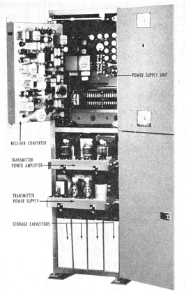
Receiver-transmitter unit.-The receiver-transmitter unit (figure 6-11) contains a dual-channel
receiver, which amplifies the signal from the two
scanning switches to a level that is suitable for
operation of the video and audio indicators of the
system. It also contains the complete impulse-type transmitter, which provides the high-level
electric signal employed in echo ranging. On the
outside, this unit is a simple box without any controls.
When the upper door of the cabinet is open, only
the receiver-converter is accessible. When the
lower door is open, the complete transmitter is
accessible. In the bottom of the cabinet are
mounted four large oil-paper capacitors, which
constitute the energy storage for the high-power
pulse. On the cabinet structure directly above
the capacitors are mounted two interlock switches
operated by the door. One disconnects the 3,700-volt power supply, and the other short-circuits the
capacitor bank, thereby minimizing the hazard
from extremely high potentials.
Directly above the storage capacitors is a
drawer that contains the high-voltage supply for
the transmitter. Directly above the power-supply chassis is another drawer that contains the
transmitter-power amplifier. To prevent possible
hazard to maintenance personnel, the upper
portion of the cabinet is separated mechanically
from the transmitter section by an expanded
metal grill. The receiver-converter unit is the
vertical chassis mounted in the front part of the
upper portion of the cabinet. The chassis contains the complete twin-channel amplifier plus the
converter section, which provides the output-frequency signal at a suitable level for driving the
power amplifier. The tuning range provided is
from 22 to 29 kc. The transducer that is furnished
with the equipment is useful only over the range of
from 24 to 27 kc.
Other operational controls on the chassis are (1)
audio gain control, which provides for adjustment
of the level of the audio output with respect to the
video; (2) doppler-nullifier gain control, which provides for the "stiffness" of response of the doppler-nullifier circuit; (3) converter gain control, which
adjusts the level of the signal to the transmitter,
thereby governing the power-output level of the
transmitter; and (4) target-doppler nullification
on-off switch, which completely disables the target-doppler nullification circuit without disabling
own-doppler nullification. All the adjustments
described here are of the screw-driver locking type.
The transmitter power amplifier is contained in
a drawer in the upper portion of the transmitter
section of the cabinet. In it are mounted 3 type-715C beam-power tetrodes, the filament transformer, the input transformer from the converter,
and the output transformer tuning capacitors.
The unit is extremely simple and contains a minimum of internal components. No adjustments
are involved in the circuit.
Electrically, the function of the unit is to accept
from the converter an r-f signal pulse of relatively
low power. The unit amplifies this pulse to a
power level of approximately 7 kilowatts maximum, which attenuates approximately 3 ½ db
during the pulse time. This attenuation is
characteristic of a pulse-type plate supply.
The transmitter power supply has the single
function of charging the storage capacitors during
the interval following the echo-ranging transmitting pulse. This power supply consists of a
large power transformer, the primary of which is
in series with a current-limiting reactor; the
secondary supplies the plates of two type-866A
rectifier tubes. The cathodes of these tubes are
connected directly to the storage capacitors and to
a resistance network, which serves as a bleeder.
These resistors are mounted on the underside of
the chassis, and a portion of the combination is
paralleled by the voltmeter on the power-supply
plate.
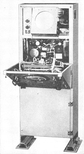
Sonar indicator control. -The sonar indicator-control unit (figure 6-12) is the sonarman's station
and contains all the operating controls.
In the upper portion of the cabinet is mounted
the assembly of the cathode-ray tube. Immediately to the left of this assembly is a small
control panel. On it a toggle switch provides for
selection of peak or band filter in echo-ranging
operations. In the peak position it provides
target-doppler nullification if this feature has not
been disabled by the switch in the receiver. It
is undesirable to echo range with this switch in
the peak position if the target-doppler nullifier
circuit has been disabled in the receiver, because
the peak filter is so sharp that a target with
appreciable doppler provides very little audio
indication. In the band position an RC band
filter is inserted, and target-doppler nullification
is eliminated. On this same control panel are
two potentiometers, one governing the threshold
signal of the cathode-ray tube and the other
governing the intensity of the electronic bearing
line or cursor. In the rear of the upper portion
of the cabinet is mounted the second-anode supply
of the cathode-ray tube.
Remote indicator. -The remote range and azimuth indicator is essentially a cathode-ray tube
repeater. Associated with it is a loudspeaker.
This remote installation gives a complete duplication of the visual and audible indications available
to the sonarman. The design of the QHB-a is
such that two range and azimuth indicators may
be installed with each equipment.
The upper portion of the front panel of the
remote indicator contains a circular opening
covered by amber filter glass through which the
cathode-ray tube is viewed. Surrounding this
opening is an azimuth ring identical with that on
the sonar-indicator control. Below the panel to
the right are various controls-the threshold-intensity and focus adjustments of the cathode-ray tube, the video-signal level adjustment, and
the loudspeaker volume control. These controls
make possible the complete and independent
adjustment of visual and audible indications at
the remote station as long as the sonarman
operates the equipment at a reasonable level.
Transmit-Receive Switching
The 48-transducer unit, the transmitting capacitors, and the signal transformers from the
connection for transmission to those for reception
are switched by two contacts on keying relay
K401. For transmission, each capacitor should
be in series with a transducer unit, and the
preamplifier input transformers should be connected so that the voltage developed across each
of them by the transmission pulse is small. For
reception, each transformer should be connected
to its respective transducer unit, which is paralleled
by a capacitor.
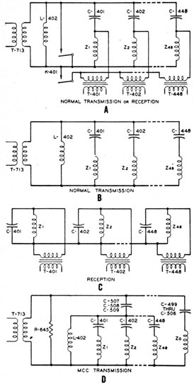
These switching connections are shown in
condensed form in figure 6-13, A, where the
connections for transmission occur when the relay
contacts are open and where the connections for
reception occur when these contacts are closed.
The 48 transmitting capacitors, C401 through
C448, are connected in series with their respective
transducer unit, Z1 through Z48. One terminal
of each of the 48 input transformers also is connected to the corresponding transducer unit;
the other terminals are connected together during
transmission and are separated from ground by
keying relay K401.
135
Figure 6-13 -QHB-a transmit-receive switching.
If the capacitors, transducer units, and transformer input impedances were identical in each of
the 48 circuits, the a-c potentials applied to the
transformers would be equal and the return circuit
from the transformer common connection would
be open. This condition would result in no voltage across the transformer primaries. Hence, the
voltages existing during transmission in any of the
48 transformers have a value that depends on the
inequalities of the 48 capacitors, transducer unit,
and transformers. As a result, the circuit for normal transmission can be shown functionally, as
in figure 6-13, B.
Each transducer unit, Z1 through Z48, including
40 feet of cable, has a nominal impedance of 58+
j82 ohms at center frequency, and the series capacitors, C401 through C448, produce a total effective
impedance for each unit of 58-j400 ohms. The
48 parallel circuits then present, at 25.5 kc, an
impedance of 1.21-j8.35 ohms. The tuning inductor, L402, in parallel with this combination,
has a reactance of 8.8 ohms. These values produce a load that is equivalent to approximately
50 ohms on the output transformer, T713.
Figure 6-13, C, shows the equivalent circuits for
reception. The impedance of the signal source,
which consists of a transducer unit paralleled by
one capacitor, becomes equivalent to 81+j86
ohms. Hence, the transformers are designed to
reflect the input impedance of each preamplifier
circuit and produce a primary impedance of 81-j86 ohms, which results in a conjugate impedance
match to the transducer circuit and the greatest
transfer of energy.
To provide a broader vertical beam pattern and
to reduce the transmitted acoustic intensity in the
horizontal plane, a condition called MCC transmission can be established for purposes of maintaining close contact.
In addition to the main units, the series-connected ring of 48 short units-located in the upper
end of the transducer and called the MCC ring-is used to transmit with a broad vertical pattern.
This ring is not involved in reception. Some
power is supplied to the remaining transducer unit,
with phase and amplitude relations between these
units and the MCC ring sufficient to cancel the
transmitted intensity along the horizontal axis.
This cancellation reduces surface-reverberation
effects. The circuit with the MCC connections is
shown in figure 6-13, D.
Directional Sensitivity Circuits
General -The directional sensitivity circuits
cover the signal-receiving function from the transducer, through the preamplifiers and scanning
switches to the receiver.
In the receiving condition the de-energized keying relay connects the 48 transmitting capacitors
in parallel with their respective transducer units.
136
The keying relay also bridges the primaries of the
48 preamplifier input transformers across the transducer units. Each of these transformers provides
a conjugate impedance match between (1) the
transducer-unit circuit, including the capacitor,
and (2) the input impedance of the preamplifier
tube. Because the 48 preamplifier circuits are
identical, this discussion deals only with one of
them. The signal from the transformer is connected to the control grid of the left side of the twin
triode, which is connected as a voltage amplifier
with a gain of approximately 20. The output is
connected to the right side of the twin triode,
which is operated as a cathode-follower. Thus,
it is a low-impedance source for transmission to
its corresponding segment on the stator plate of
the audio and video scanning switches. Similarly,
the remaining 47 preamplifiers deliver the amplified transducer-unit signals to the other 47 capacitor segments on each scanning-switch stator.
Beam-pattern formation and rotation. -One function of the equipment is to produce electrically an
acoustic pattern, continuously rotatable through
360°, using a fixed cylindrical array of hydrophones
or transducer units. This function is accomplished
by two devices-(1) the electric circuits necessary
to produce the beam pattern and (2) the electro-mechanical means for rotating this pattern.
The production of an optimum beam pattern
from a fixed array of radiators or receptors is a
fairly well known art and consists either in (1)
choosing amplitudes and phases for the currents in
the radiators or (2) modifying the voltages from
the individual receptors-depending on the geometry of the array. The phasing requirements are
imposed because this array of transducer units is
cylindrical. Therefore, the signals received by
each unit from a plane sound wave, unlike the
signals that exist in a plane-faced transducer,
differ in phase in proportion to their physical displacement. The total voltage from a group of
units facing the sound source is a maximum when
all the signals have been shifted so as to be in phase
with one another. The resulting beam pattern is
similar to that of a plane-faced transducer of
approximately equivalent dimensions. This phasing requirement is accomplished by the use of a
linear phase-shift "lag line" in order that the
phasing may remain correct when the frequency is
changed.
The usual beam pattern for this type of transducer consists of a major lobe, accompanied on
each side by minor lobes that decrease in sensitivity as the angle from the main lobe increases.
Altering the relative amplitude of the side-lobe
signals (shading) can result in a reduction of the
level of the more adjacent minor lobes at the expense of increasing the very small lobes, which
are at a large angle from the main beam. The
optimum signal-to-noise ratio occurs for such
shading when the minor lobes have all been
brought to the same level, and consequently the
main beam is widened only slightly. Design
engineers select the proper fraction of each of the
signals that are to be phased and added so as to
provide this shading.
Lag-line phasing and shading. -The beam-pattern formation can be analyzed by (1) inspection of the voltages produced by the transducer
units, (2) the required phasing, and (3) the choice
of shading.
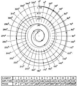
The first of these methods, involving a single-unit pattern, may be presented in several ways, one
of which is shown in figure 6-14. This illustration
shows that the total lagging phase shift for the
signal from unit 1 is at least 680° in order to bring
it into phase with the signal from unit 8. The
Figure 6-14 -QHB-a transducer-unit voltages.
137
Figure 6-15 -QHB-a lag line and equivalent circuits.
phase shift for the voltage from unit 2 is 31° less
than that from unit 1.
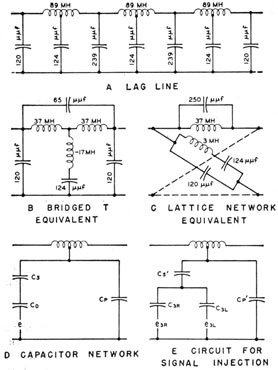
To accomplish the necessary phase shifts, the
simplest lag line is a uniform line of as many sections as required to match the desired angles with
whole or half sections. One limitation is that the
phase shift per section must be kept below approximately 60° in order to approach linear phase shift
with frequency. The final lag line as designed has
a phase shift of 52° per full section at 26 kc and
consists of 14 sections. The physical arrangements
for three sections are shown in figure 6-15, A. The
proper choice of entry points for the signal voltages
allows a good approximation to the required phase
shifts. The electrical equivalent of this circuit for
a single section is shown as a bridged-T network in
figure 6-15, B, and as the equivalent lattice network used in design in figure 6-15, C. This circuit
results in a characteristic impedance of 16,300
ohms at 26 kc.
A method of injecting the signal voltages from
low-impedance generators has been devised. This
method does not impose any loading of the lag line
or mismatching at any point, which would result
in standing waves of voltage on the line. Because
the scanning switch must introduce these voltages
through the capacitance of the segments on the
stator and rotor plates, this capacitance is made a
part of a network of three capacitances, through
which is injected a voltage (figure 6-15, D).
Two units of the scanning-switch circuit that
are symmetrically disposed about the center of the
beam-forming network (such as 3R and 3L in
figure 6-17), introduce signals at the same point
on the lag line. The complete circuit for signal
injection is shown in figure 6-15, E. The values
are related because the total capacitance must
equal the value required (1) by the lag line at the
point of signal injection and (2) by the desired
fraction of the signal voltage that is to appear on
the lag line.
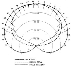
The optimum beam pattern requires an attenuation or shading of the transducer-unit voltages.
The desired total attenuations are shown in figure
6-16, with the attenuation already present, that
is due to the single-unit pattern. The ratio of the
single-unit pattern to the total attenuation for any
unit determines the attenuation that must be introduced by the beam-forming network. This
Figure 6-16 -Shading curves.
138
attenuation is accomplished by the choice of capacitance values shown in figure 6-15, E. The combination of these circuits results in a complete
scanning-switch circuit, illustrated in figure 6-17.
Because the phase shift from unit 7 to unit 8, and
from unit 8 to unit 9, is approximately 180°, a
voltage also is used from unit 9 and is introduced
into the same point as that from unit 7.
A typical resultant beam pattern has (1) a major
lobe 11° wide at a level that is 6 db below the peak
sensitivity and (2) minor lobes that are at least 25
db below the same reference level.
Figure 6-17 -QHB-a scanning-switch circuit.
139
Scanning switches. -The video and audio
switches are identical both structurally and electrically. Structurally, they each consist of two
large cast-iron cups accurately doweled and bolted
together at their open ends. At the left end of the
assembly is a circular terminal board, to which are
connected the 48 output leads from the preamplifiers. These leads are connected directly by short
conducting loops to pins that protrude through the
left-hand surface of the scanning switch proper.
The pins are insulated by rubber grommets.
A glass disk, 11 inches in diameter and 7/8 of an
inch thick, is bolted securely to the machined surface of the left-end bell. The outer plane surface
of the disk is coated with silver and scribed with
48 radial divisions, which form separate conducting segments. After 48 holes have been drilled
completely through the segments and the glass,
they are metalized. In this way the segments are
connected electrically to the back of the hole,
where connection pins are soldered, thereby providing a complete circuit from any specific preamplifier to a corresponding segment. Each of
the rotors consists of a glass plate (identical to the
stator plate), which is secured to a large steel hub
that has been shrunk on the rotor shaft. With
the rotor shaft mounted in place, there is an air
gap of approximately 0.004 inch between the glass
plates.
With the segments of both rotor and stator
lined up, 48 equal capacitors of from 80 to 100
micromicrofarads are formed. These capacitors
constitute the means for connecting the outputs
of the preamplifiers to the electrical network
carried on the rotor assembly. This network
provides the proper phasing and attenuation of
the signals from any 18 consecutive stator elements in order to form an acoustic beam. The
network is mounted in a cast-aluminum can, and
the output connections are carried to suitable slip
rings mounted on the rotor shaft. Carbon-silver
brush members inserted through the rear wall of
the right-end bell engage these slip rings, thus
making accessible the electrical-signal equivalent
to the acoustic information that is obtained at
any instant.
Because of the necessary high rate of rotation
of the video switch the signal from an echo is not
sufficiently long for audio presentation. Therefore, two switches are needed. The inputs of
these switches are parallel-connected, and their
outputs are connected to individual receivers-one for video and the other for audio presentation.
The system lined-up for the receiving functions
is as follows:
1. Each transducer unit connects through its
own preamplifier to a stator segment on the
audio scanning switch and to the corresponding stator segment on the video scanning
switch.
2. The output of the video scanning switch
connects to the input of the video receiver,
the rectified output of which is used as the
brightening signal for the control grids of the
cathode-ray tubes.
3. The output of the audio scanning switch
connects to the input of the audio receiver,
the output of which is used to drive the loudspeakers and to mark the tactical range
recorder.
The azimuth angle of the video scanning-switch
rotor at any instant is indicated on the cathode-ray
tube by a 5HCT control transformer. This control transformer is used as a 3-phase sweep
generator-a unique employment of a synchro.
In the usual synchro system the rotor is energized by a single-phase a-c voltage. Therefore, the
stator coils remain in time phase but vary in magnitude, depending on the angle between the axis
of the magnetic field and the axis of each stator
coil. When these voltages are connected to a
synchro receiver they duplicate the magnetic
axis of the transmitter. The 5HCT synchro used
to generate the sweep voltage is excited by a direct
current, the magnitude of which is proportional
to the range of the active volume at any instant.
The output therefore is a true 3-phase voltage
with the peak magnitude of the voltage in each
phase increasing with time. If the excitation remained at a constant value this arrangement would
be the same as that in any 3-phase generator the
rotor of which is d-c-excited and rotated in a
3-phase stator.
The rotor of the 5HCT synchro that is used to
generate the sweep voltage is geared at a 1-to-1
ratio to the video scanning-switch rotor. When
the system is in motion a 3-phase voltage proportional to range and synchronized in bearing is
available at the stator terminals. Because the
rotational speed is about 1,750 rpm, the output
140
frequency is slightly less than 30 cps. This polyphase signal provides relative bearing of the video
beam in the deck plane.
For conversion to true bearing with stabilization,
the signal is taken to the data converter and is
applied to the stator terminals of a 5SCT synchro,
which is used as a polyphase phase-shifter. The
rotor of the 5SCT is positioned primarily by the
ship's gyro order with a stabilizing component
related to azimuth sonar train. The output at the
rotor terminals of the 5SCT synchro is therefore a
3-phase true bearing sweep signal that is stabilized
in a horizontal plane, with respect to the line of
sight. The three components must be amplified
by three identical feedback amplifiers so as to provide sufficient signal for the deflection coils of the
cathode-ray tube. These coils are the stator
coils of a 5SCT synchro.
Depth-Determining Equipment
MODEL QDA
General
The model QDA depth-determining equipment
is an ultrasonic echo-ranging equipment operating
in the frequency band of 50 to 60 kc. It is
primarily an attack instrument and is installed in
conjunction with an OKA-1 sonar resolver and an
azimuth sonar equipment, which may be either
the QHB-a or the QGB. The differences between
the QDA equipment and a standard azimuth
search equipment lie chiefly in the transducer and
the recording mechanism.
As with ordinary echo ranging, range is determined by the ping-to-echo time lapse and the
velocity of sound. For determining the depression
angle, the QDA transducer, which has a sharp
beam in the vertical plane, is pivoted on an
athwartship axis to permit the beam to be tilted
to any necessary depression angle. In depth
search, pings are sent with the beam tilted at
various angles. When the beam is directed toward
a target, echoes are detected if the target is within
range, and the tilt of the beam at the time such
echoes are received corresponds approximately to
the target depression angle Eq. After depth contact with a target, the alignment of the beam with
the target depression can be indicated more accurately by a depression deviation indicator (DDI),
which is analogous to the bearing deviation indicator employed in azimuth sonar systems.
Depth is indicated automatically by a depth
recorder, which is similar in principle and construction to the tactical range recorder and the
indicator range recorder. In the depth recorder,
however, the stylus travels at a speed proportional
to the sine of the target depression angle, which is
the vertical component of the velocity of sound,
239276°53-10
Vz. The stylus moves at a rate corresponding to
the slope of the sound beam. If the beam is
steeply inclined the stylus moves rapidly from left
to right; if the beam is nearly horizontal the stylus
moves slowly. The ping is transmitted just as
the stylus moves away from its zero position, and
the stylus marks the recorder paper at the instant
the echo returns.
For a distant target the depression angle is
small, and correspondingly, the stylus moves slowly
but for a relatively long period before the echo
mark is recorded. For a nearby target the depression angle is relatively large, and as a result the
stylus moves rapidly for a short period before the
echo returns. In both cases the echo is recorded
at the same distance from the starting position of
the stylus. A linear depth scale, reading in feet,
extends across the recorder chart. The stylus
speed is controlled by the OKA-1 resolver, but
the basis of this speed is determined by the QDA
beam depression angle and the velocity of sound
in water. When the bypass switch is in the search
position the azimuth transducer only is stabilized.
When the bypass switch is in the attack position
both the azimuth and the QDA transducers are
stabilized.
Keying and Controlling the Recorders
The keying interval for both the azimuth and
the QDA echo-ranging systems is controlled by
the sound-range recorder, a unit of the OKA-1
equipment. When the fly-back contacts of the
sound-range recorder are closed, the action of the
keying circuit in the azimuth equipment and of a
similar circuit in the OKA-1 resolver are both
initiated. The latter circuit controls the depth
recorder and keys the QDA. These timing circuits cause the stylus clutch to release in the
141
indicator range recorder of the azimuth equipment,
and of the depth recorder so as to allow the respective styli to fly back and dwell for a brief
period. The clutches are then re-energized, and
almost simultaneously the two equipments are
keyed.
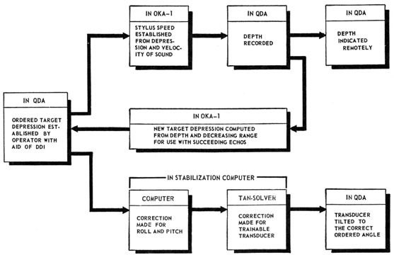
The general arrangement and sequence of operations of the units of the different equipments are
shown in the block diagram of figure 6-18.
If the depth recorder reaches the end of its
travel before the fly-back contacts of the sound-range recorder are operated, the stylus flies back
and dwells until the sound-range recorder initiates
another keying cycle. When the sound-range
recorder is turned off, the depth recorder is no
longer slaved, and it controls its own keying cycle
through the OKA-1 resolver timing circuit.
Horizontal Range and Computed Target Depression
The sound-range recorder is provided with an
adjustable cursor, the position of which represents
sound range, Rq. Rq is transmitted by synchro
to the predictor resolver circuit of the OKA-1
resolver unit. The depth recorder likewise is
equipped with a cursor, the position of which
represents target depth below the transducer,
H'q, which also is transmitted by synchro order
to the predictor resolver circuit. From these two
inputs the OKA-1 resolver computes the following:
1. Horizontal sound range, Rhq, which is transmitted to the horizontal recorder and to the
remote indicators of the QDA equipment.
2. Sonar target depth, Hq, which also is transmitted to the remote indicators.
3. The computed sonar target depression, cEtq,
which is transmitted to the tilt-control differential generators in the QDA console as an
aid in maintaining contact.
The operator of the QDA console modifies the
order cEtq by an adjustment of the tilt wheel
under guidance of the DDI. The order introduced by the operator is known as adjustment of
computed sonar target depression, jEtq. If the
azimuth beam is centered on the target, as indicated on the DDI, the order leaving the console
represents apparent depression of the acoustic
path to the target, Eq. The order Eq is the sum
Figure 6-18. -Sequence of operations for determining target depth.
142
of cEtq and jEtq. This order is indicated on the
console by a synchro that positions an indicator.
Correction for Bending of the Sound Beam
The order Eq is transmitted to the stabilization
computer by way of the bypass switch and the
Snell's law resolver circuit of the OKA-1 resolver
unit. The purpose of the Snell's law resolver
circuit is to establish the speed of the depth-recorder stylus so that its excursion rate is proportional to Vz. If the beam is vertical, the
vertical component of the velocity of sound along
the beam is simply the velocity of sound in water
at the prevailing temperature. If the beam is
horizontal, Vz is zero.
The Snell's law resolver computes and establishes Vz from the input information consisting of
(1) the Eq order; (2) the velocity of sound, Vo,
which is injected manually into the circuit; (3) the
difference of velocity in the mixed layer and the
refracting layer, V, also manually injected; and
(4) the layer-depth timing introduced by the
closure of the layer-depth contacts in the depth
recorder at the appropriate point in the stylus
excursion. The layer-depth contacts in the depth
recorder are adjusted manually, and information
for this setting of Vo and V in the Snell's law
resolver and for Vo in the sound-range recorder
are derived from bathythermograph information.
Tilt-Order Synchro Circuit
As has been stated, the depression angle order
originates in the OKA-1 resolver, where it is computed and transmitted by synchro transmitters at
2 and 36 speed. For on-target conditions, this
order is called cEtq. It is delivered to a pair of
DG synchros to permit the operator to modify the
computed order so as to center the beam on the
target as indicated by the DDI. The signal
introduced by the operator is jEtq. The output
of the DG synchros is the sum of the two inputs
and is equal to Eq, provided the azimuth and depth
beams are on the target. A synchro receiver,
which operates the tilt dial in the console, is connected to the output of the 2-speed DG to indicate
this adjusted order.
It is important to understand the significance
of the tilt dial indication. Whether or not the two
acoustic beams are centered on the target, the indication represents the depression of the QDA
beam below the horizon along the bearing of the
azimuth beam, provided the computer is not bypassed. For on-target conditions, this angle is
equal to Eq, the true depression at the transducer
of the acoustic path to the target. In the absence
of refraction or bending of the QDA beam, Eq is
equal to Etq, the true depression of the target.
The true tilt angle of the transducer below the
horizon is equal to the indicated angle, Eq, provided the azimuth transducer is trained dead
ahead; but the true tilt angle exceeds the indicated
angle by increasing amounts as the azimuth transducer is trained farther off the bow. When the
bypass switch is in the bypass position, the tilt
indicator shows the actual tilt of the QDA transducer with respect to the deck plane, and the
transducer tilt is unaffected by the position of the
azimuth beam.
The 2-speed output of the differential transmitters in the console is connected to the OKA-1
resolver to operate the Snell's law resolver, which
controls the stylus speed of the depth recorder.
This 2-speed output also is connected to the stabilization computer, which corrects it for the roll and
pitch of the ship. This corrected order for on-target conditions is E'q, which represents the
depression of the beam relative to the deck, measured in a plane through the line of sight perpendicular to the deck. E'q also is the order that
would control the tilt of the transducer if the transducer were trained to the bearing of the target.
For the QDA system, however, the E'q order is
transmitted to the tangent solver of the computer,
where it is converted into a transducer tilt order
that causes the fan-shaped beam to pass through
a target, which is at the bearing of the azimuth
transducer. The transducer tilt order is E'q's.
E'q's is transmitted at 2 and 36 speed, by way
of the tangent solver, to the control transformers
on the tilt-control mechanism. The signals from
these control transformers are connected to the
tilt-control amplifier, which supplies the power to
the tilt motor that drives the transducer to wipe
out the signals and thus bring the transducer to
the ordered angle, E'q's.
The tilt of the QDA transducer is controlled
by the following factors:
1. Factors controlling the depression order from
the console. These factors are combined
and then are indicated by the tilt indicator
on the console.
143
a. The computed target-depression order is
based on the position of the depth-recorder
cursor and that of the cursor of the sound-range recorder. If either of these positions is changed, the order from the resolver to the QDA console changes.
b. The position of the two differential-transmitter rotors located in the console
is controlled by the tilt wheel.
2. Factors controlling the correction of the
depression order from the console. These
factors affect the transducer tilt but not the
position of the tilt indicator.
a. Roll and pitch correction orders. These
stabilization orders are incorrect if the
azimuth beam is not centered on the same
target as the QDA beam.
b. The alteration of depression order by the
tangent solver to supply additional depression for targets on either side of the bow.
The correction is necessitated by the non-variable fan-shaped beam.
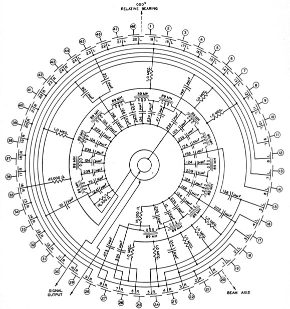
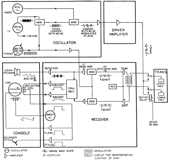
Figure 6-19 -Block diagram of the QDA transceiving system.
144
Transceiving System
The block diagram of the QDA transceiving
system is shown in figure 6-19. The signal transmitted through the water is produced by inter-modulating the outputs of three oscillators shown
in the figure. The 190-kc i-f oscillator is a fixed-frequency generator labeled "IF" because it
establishes the intermediate frequency in the
receiver. The unicontrol oscillator with a frequency range of from 240 to 250 kc (1) establishes
the r-f carrier and (2) tunes the receiver to that
frequency. The 0.8-kc audio oscillator originates
the audio frequency that is heard when an echo or
reverberation is received.
The oscillator with a frequency of from 240 to
250 kc is heterodyned with the 190-kc oscillator to
produce a difference frequency of between 50 and
60 kc at the output of the first modulator. This
difference frequency is the r-f carrier frequency.
Because the 190-kc source is blocked except while
the transmitter is keyed, the carrier exists only
during the key-down condition. The carrier then
is modulated with the audio frequency to produce
the signal that is transmitted through the water.
In the modulation process, negative half cycles of
the relatively high level of the 0.8-kc oscillator
blocks the modulator. The resulting modulated
signal then consists alternately of a group of oscillations having a frequency of from 50 to 60 kc
followed by an equal period of zero signal (figure
6-19). This modulated signal is composed of the
carrier frequency and the side-band frequencies
spaced at frequency intervals of 0.8 kc. The modulated carrier is amplified in the transmitter amplifier unit and is conducted through the transducer
keying relays to the two halves of the transducer,
which are connected in parallel.
The echo returning through the QDA transducer
is similar to the outgoing signal except that the
frequency of the echo has been shifted by Doppler.
In the upper channel, marked "sum," the signals
from the two halves of the transducer are combined
to produce the signal that would be obtained if the
transducer were not split. This signal is amplified in two r-f stages and passes through a modulator, where it is heterodyned against the frequency between 240 and 250 kc. In the absence
of Doppler, the difference frequency is 190 kc-exactly the frequency of the i-f oscillator, although
the signal shape is different because of the 0.8-kc
modulation. The Doppler always shifts this frequency to 190-D, the direction of shift being
reversed by the heterodyning action.
In passing through the tuned i-f circuits, the
higher-order side frequencies are filtered out and
the modulated signal assumes a more nearly sinusoidal envelope. The detector rectifies this signal
to produce an 800-cps signal similar to the envelope
of the i-f signal. The frequency of the audio signal
is 0.8 kc-D X(0.8/55); that is, the audio frequency
is shifted by only about 1.5 percent of the original
Doppler shift.
The reason for this shift can be understood if the
modulated signal in the water is thought of as
consisting of only three frequencies-the 60.000-kc
carrier, the 59.200-kc lower side band, and the
60.800-kc upper side band. Because the Doppler
effect shifts the frequencies by 0.7 cycles per kilo-cycle per knot of range rate, a range rate of 20
knots, closing, shifts the named frequencies to
60.840, 60.029, and 61.651 kc, respectively. The
same frequency differences are preserved through
the i-f circuit. The audio frequency produced
when the signal is demodulated in the detector is
the difference between the carrier and the side
bands, or, in this example, 0.788 kc. Thus, the
audio shift is only 12 cps (Doppler shift of the
0.8-kc modulation component), whereas the original Doppler shift is 840 cps. Obviously, the doppler would be very troublesome if the full shift of
840 cps were carried over into the audio signal, as
it is in azimuth systems working in the frequency
band of from 20 to 30 kc.
The virtual elimination of Doppler in the audio
permits the use of a narrow pass filter in the audio
circuit with significant benefits in noise reduction.
The signal in the sum channel, traced in the
foregoing description, is formed vectorially by adding the signal outputs of the two halves of the
transducer. The signal in the diff channel-the
lower channel in figure 6-19-is formed from the
vector difference between the signals in the two
halves of the transducer. The diff signal is zero
if the transducer beam is centered on the target
in the vertical sense. The diff signal, which has
the same character as the sum signal, is heterodyned in the same way as the sum signal. After
suitable amplification, the diff signal, together with
a portion of the sum signal, is fed into the conjugate
145
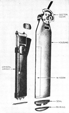
Figure 6-20 -QDA transducer.
rectifier. As a result two d-c outputs are produced-one proportional to the sum signal plus
the diff signal, and the other proportional to the
sum signal minus the diff signal. These two d-c
signals are transmitted to opposite ends of the
vertical-deflection coil of the DDI oscilloscope in
the console. If the sum-plus-diff signal is greater,
the electron beam is deflected upward, indicating
that the target is above the transducer beam. If
the sum-minus-diff signal is greater, the spot is
deflected downward, indicating that the target is
below the beam. The two d-c signals are equal
when the beam is on the target because the diff
signal is then zero.
The two d-c signal-return currents, added together, flow out of the mid-point of the deflection
coil, and this combined signal (1) supplies voltage
to operate the intensity grid of the cathode-ray
tube to cause brightening when an echo is received,
and (2) supplies current through the recorder-stylus chart-paper circuit to produce marks on the
chart when echoes are received. These circuits
are discussed more thoroughly in chapter 7.
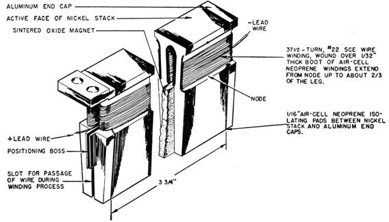
Transducer
The transducer is of the ADP crystal type. It
is shown in figure 6-20. The crystals are in an
array approximately 20 inches long and 1 1/8 inches
wide and are mounted in groups-each group ½
inch long and 5/16 inch wide-on a steel base-plate
that has integral resonators directly behind the
crystals. This arrangement provides efficient
half-wavelength units with a nodal point at the
face of the base plate. The array is connected
electrically into separate halves about a horizontal
centerline. Each half is connected to the high
side of a transformer, the low sides of which provide impedance matches to the transmitter and
receiver amplifier circuits. Gold-to-gold contacts
between the crystals and their electrodes provide
low interface electric resistance and consequently
reduced heating. The gold surface is applied by
evaporating gold onto the crystal faces and then
bonding gold-plated metal foil to these faces.
The crystal array and resonator-plate assembly
are mounted, with their long axis vertical, inside a
streamline corrosion-resistant steel housing having
a thin corrosion-resistant steel window that is almost sound-transparent. Also mounted inside the
housing are two transformers, as well as a laminated baffle that attenuates extraneous signals
through the back of the transducer. A blanket of
the baffle material is assembled along the sides and
back of the resonator assembly and helps to reduce
the effects of reflections within the housing. At
the top of the housing is an integral pivot block,
on which are mounted a sector gear and trunnion
bolts for attachment to the hoist-tilt mechanism.
A cover plate near the top of the housing provides
access to a cable seal and filling plug. Another
cover at the bottom of the housing provides access
to a second filling plug in a rubber-gasketed plate
and ring assembly, which seals the housing.
The transducer is vacuum-filled with approximately 1 gallon of electrical-grade castor oil, from
which the air and water vapor have been removed.
The transducer is a highly efficient reciprocal
converter of electric into acoustic energy over a
frequency range of 50 to 60 kc. This wide range
146
makes possible a choice of frequency that permits
simultaneous operation of equipment by several
ships in the same area. The beam pattern is very
sharp in the vertical plane so as to permit the
accurate determination of target depth. In the
horizontal plane the pattern is broad so that contact with the target can be maintained over a wide
angular range on either side of the bow of the
ship. Figures 6-21 and 6-22 illustrate typical
beam patterns in both planes.
The crystal array of the transducer is divided
electrically into top and bottom halves for obtaining
depression deviation indications.
Transmitter
From the output of the second modulator a
voltage of from 50 to 60 kc ±0.8 kc is delivered to
the grid of the transmitter preamplifier, a type
6SJ7 tube. From the preamplifier output this
voltage is used to excite the control grids of the
transmitter-amplifier stage, which consists of six
type-807W beam-power tetrodes connected in
push-pull with three tubes in parallel on each side.
The output of the transmitter is connected to the
transducer through a tuning retard coil, which has
several taps that facilitate tuning out the
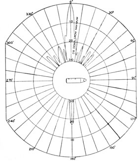
Figure 6-21. -Typical vertical beam pattern of a QDA transducer at 55 kc.
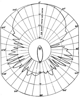
Figure 6-22 -Typical horizontal beam pattern of a ODA
transducer at 55 kc.
capacitance of the transducer and approximating an
impedance match between the amplifier and the
transducer. The plate-to-plate impedance of the
output circuit should be 3,300 ohms for maximum
power output, which is 150 watts.
Summary
The QDA target depth-determining equipment
and the azimuth sonar equipment when operating
together provide complete and continuous information regarding the location of a submerged
object. The sole function of the QDA is to
determine the depth of a submerged object,
whereas the azimuth equipment determines the
range and bearing of the target.
The QDA determines target depth indirectly
because it is an echo-ranging equipment that
measures the time lapse between transmission and
echo. The vertical velocity of the sound beam is
measured by a chemical recorder that has a variable-speed stylus. The stylus speed is a function
of the sine of the depression angle times the
velocity of sound. The stylus speed is controlled
by an associated equipment-the OKA-1 recording-resolving equipment-but the basis of the
147
stylus speed is the QDA beam-depression angle
and the velocity of sound in water. To obtain
accurate depth solutions the equipment has a
cathode-ray tube used as a depth-deviation
indicator.
Because the target-depth information is employed at various locations on the ship, a means
for transmitting the information is provided by an
optical cursor that positions a synchro transmission system.
While the sonar vessel is closing a target, the
depression angle increases-slowly at first, and
more rapidly as the range is decreased. To
relieve the operator of most of the burden of
following the target, the OKA-1 provides aided
tracking by (1) computing the depression angle
theoretically required-known as the computed
target depression, cEtq-and (2) transmitting this
synchro order to the QDA tilt-order system. The
QDA operator then adds corrections, jEtq, to this
order, guided by the indications of the DDI.
The QDA beam must be stabilized against roll
and pitch, and the depression orders originated by
the QDA operator must be modified accordingly.
This action is accomplished by the stabilization computer, with which a stable element is
associated.
The transducer cannot be trained in azimuth.
When the target is dead ahead, the target depression corresponds to the transducer tilt-if
the sound path in the water is a straight line.
When the target bears off the bow, contact still
can be maintained because the transducer beam is
very broad in an athwartships direction, but a
greater tilt is required to keep the fan-shaped beam
on the target. This correction to the depression
angle is made by the tangent solver, which is a
unit of the stabilization computer.
The sound path through the water generally
undergoes some bending, principally because of unequal temperatures at various depths. The OKA-1 equipment makes the correction for bending by
varying the stylus speed of the depth recorder.
While the sound energy is passing through the
mixed layer, the path does not bend and the stylus
speed is constant. During this period the stylus
speed is based on the sound velocity near the surface and the ordered depression angle. Below the
mixed layer the sound energy travels at a speed
that varies with depth, and as a result the beam
is bent.
If the beam is bent downward, the stylus speed
is increased for a corresponding period because the
depression angle is greater than the ordered angle.
Layer-depth contacts, closed by the stylus carriage, are adjustable and bring about the transition
from the mixed-layer travel rate to the refraction-layer rate. The layer-depth contacts in the depth
recorder and the two sound-velocity controls in
the OKA-1 resolver are set according to the information from bathythermograph readings.
SONAR INSTALLATIONS
The sonar system installed on antisubmarine
vessels is composed of several sonar and fire control equipments operating in a reciprocal-information and control network. The purpose of the
system is to fix a submarine's position once contact
has been established and to solve the necessary fire
control problems to assure a kill. The system is
an attack system and not a search system. There
has always been a need for a fire control system in
antisubmarine warfare, but the need did not become acute until the advent of the high-speed,
deep-diving submarine. At the outbreak of
World War II the depth of the submarine was
approximated by the conning officer from the
range at which contact was lost because of the
sound beam passing over the U-boat. By the
time the lost-contact range was reached the anti-submarine vessel was on its attack course, and was
already starting to lay the depth-charge pattern.
In spite of this difficulty, the method was fairly
effective against the old type of submarine with
riveted construction because the pressure hull
could be ruptured by near-misses. With the advent of the modern welded-hull construction, which
can stand terrific pressures and stresses, it became
necessary to score a direct hit on the submarine to
do a reasonable amount of damage. The underwater fire control system furnishes the precise information necessary to score these direct hits. Furthermore, it supplies the information until a very
late stage in the attack. The older single-sonar
search system frequently lost contact at ranges up
to 600 yards. As a result, the submarine had
ample time to take evasive action which could not
have been detected by the attacking vessel.
A typical installation aboard an antisubmarine
vessel may consist of a QGB or QHB, a QDA, an
OKA-1, a Mark 4 director, and a stabilization
computer with its associated stable element.