Determining the depth of water to ensure safe
navigation is an old problem. The Bible mentions sounding in Chapter 27 of the Acts of the
Apostles. The passage concerns the shipwreck of
St. Paul, as follows:
"After midnight the shipmen deemed that they
drew near to some country. And sounded, and
found twenty fathoms; and when they had gone a
little further, they sounded again, and found it
fifteen fathoms. Then fearing lest they should
have fallen upon rocks, they cast four anchors out
of the stern, and wished for the day."
It is interesting that the word "sound," meaning to take depth measurement, derives from a
different root than the word "sound," meaning a
stimulus to hearing, and originally the two meanings of the word had nothing in common. Now,
however, the use of echoes for "sounding" has
established a new relation between the old meanings of the word.
Until recently the lead line was the primary
means of sounding. Today, the lead line is used
chiefly to obtain samples of the ocean bottom, because modern methods of sounding with echoes are
more efficient. The latest engine-driven lead-sounding machine, employed in some geodetic
survey operations, uses a 36-pound lead and is
capable of taking a sounding of 300 fathoms in 3
minutes.
The present method of echo sounding is automatic and rapid. A sound is transmitted vertically downward, and the time that is necessary
for the sound to travel to the bottom and return
to the surface is recorded. Echo sounding is
similar to the echo ranging described in previous
chapters.
239276°-53-18
DEPTH-FINDER REQUIREMENTS
In general, the depth finder should be capable
of the automatic recording of the depth in the
shortest possible time interval. It must be independent of the ship's speed and must be effective
in any depth of water. Depth finders in present
use satisfy these requirements. Some of the
smaller types do not have a recording unit, but
they are useful for small vessels.
The first sonic depth finders used audible sound,
which has several disadvantages. Ship noise,
which is a maximum in the audible range, causes
interference. Because the energy from the transducer cannot be concentrated into a beam, a great
part of the energy is wasted. In the sonic range
neither piezoelectric nor magnetostriction transducers can be used effectively, but there are no
substitutes for them. Ultrasonic sound overcomes
all these disadvantages.
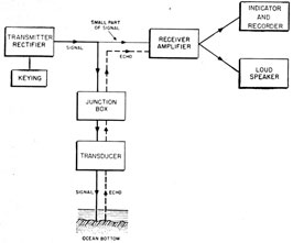
Modern depth finders have the following five
units in common (figure 15-1):
1. A transducer for the reciprocal conversion of
acoustic and electromagnetic energy.
2. An electronic or electric transmitter-rectifier
for driving the transducer.
3. An electronic receiver-amplifier for amplifying
the weak echo energy picked up by the
transducer.
4. An indicator for accurate and continuous
indication of depth.
5. A recorder for making a permanent record of
water depths over which the ship is passing.
DEPTH-FINDER COMPONENTS
Transducers used in naval sounding equipment
are of three types-two of them are magnetostrictive, and the other is a crystal type.
269
Figure 15-1. -Functional block diagram of a typical echo-sounding system.
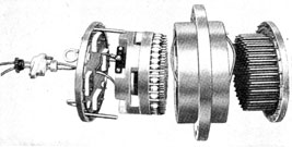
The first type, used in large equipment, is similar to that used in echo-ranging equipment (figure
15-2). It consists of a steel plate with nickel
tubes mounted on it.
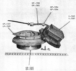
The second type is constructed of nickel laminations. The unit looks somewhat like a transformer (figure 15-3). A current passing through
the coil of the winding sets the core into vibration.
The crystal transducers are constructed similarly to echo-ranging crystal transducers except
that they are permanently positioned downward.
Transmitters are of two types. The transmitters for the magnetostriction and crystal transducers are in many respects like those used in
echo-ranging equipment. They consist of an
oscillator and a power amplifier. Transmitters
used with laminated transducers are of the impulse
type. A capacitor is discharged through the
Figure 15-2. -Exploded view of the NMC-2 transducer.
winding of the transducer, and the output is a
damped sine wave.
Indicators are usually the source of the timing
impulse to the transmitter. The type of indicators
most commonly used consists of a circular rotating
disk over a flashing neon light. The type used by
the Radio Corporation of America has a hole in a
steel tape, which continuously runs on pulleys
across the face of the indicator. A long neon light
lies behind the tape. The transmitter is keyed as
the hole starts over the end of the tube, and the
echo returning from the bottom causes the tube
to flash. During the elapsed time the hole in the
tape has traveled a distance proportional to the
depth marked on a scale beside the tape. The tape
contains several holes along its length, but only
Figure 15-3. -Magnetostriction laminated transmitting projector
of the NJ-7 equipment.
one hole appears over the neon lamp at any
instant. The tape indicator is usually not so
satisfactory as the rotating type. On a small type
of depth finder built by Bludworth Marine the
depth is indicated on a meter. The most modern
type used by Edo Corporation makes use of a
circular sweep on a CRT. Depth is indicated by
deflections of the sweep.
Depth recorders are all essentially of the same
type. They record on a time-depth chart the
depth as the time varies. The chart paper is
generally of the conducting type with a thin wax
insulating coating that is punctured by an electric
spark caused by the echo.
270
NMC-2 Sonar Sounding Equipment
GENERAL
The model NMC-2 sonar sounding equipment
is typical of that used on large vessels. It provides
a powerful oscillator that allows echoes to be
received from depths greater than 2,000 fathoms.
A pictorial view of the equipment is shown in
figure 15-4. The NMC-2 is similar to the early
type of echo-ranging equipment.
The NMC-2 equipment measures ocean depths
in fathoms by projecting a signal vertically and
measuring the elapsed time before the return of
the echo from the ocean bottom. The interval
between the emission of the signal and the return
of the echo is timed (1) by rotating a disk at a
known constant speed and (2) by noting the
angular rotation of the disk during the interval
by reference to a scale graduated to read directly
in fathoms. In depths of less than 2,000 fathoms
the operation of the apparatus is automatic, and
soundings are obtained with a minimum of
attention or adjustment of controls by the
operator. A semiautomatic method supplements
the automatic method in depths or more than
2,000 fathoms and extends the range beyond that
obtainable by the automatic method. The
semiautomatic method consists of listening for an
audible echo signal in the speaker and noting the
white-light position on the proper scale. The
NMC-2 is equipped with a recorder that automatically records ocean depths down to 2,000
fathoms.
TRANSDUCER
The NMC-2 equipment uses a magnetostriction
transducer of the type shown in figure 15-2.
It is mounted near the keel of the ship with the
diaphragm horizontal and in contact with the sea
water. The normal frequency is 18 kc.
TRANSMITTER AND RECTIFIER
The transmitter and rectifier unit contains an
electron-tube transmitter for generating the alternating voltage to be applied to the transmitting
projector, two rectifiers for the high-voltage supply, and two starting relays and switches. A
tuning control allows the transmitter frequency
to be varied over a range of from 17 to 19 kc.
This transmitter is similar to magnetostriction
transmitters described in chapter 8. A simplified
diagram of the rectifier is shown in figure 15-5.
Plate potentials for the transmitter tubes are
supplied by the duplex bridge rectifier in figure
15-5. This procedure allows virtually the full
output voltage of T406 to be made available to the
amplifier. The bridge circuit requires three
separate and well-insulated filament windings
since they are connected to opposite ends of the
load circuit and have the full-load voltage between
them.
The plate supply to the oscillators utilizes
V407 and V408 with transformer T406 as a fullwave rectifier, and delivers approximately one-half of the total transformer voltage as d-c output.
INDICATOR-RECORDER-AMPLIFIER UNIT
The indicator-recorder-amplifier unit consists of
a depth indicator-recorder and a receiver-amplifier
with its power supply mounted in the same
housing.
Indicator
The indicator portion is the principal control
unit mounted on the bridge. An equipment start-stop button allows the equipment to be turned on
from the bridge.
The timing disk rotates behind the two scales,
and a slot in this disk is exposed in the space between the shoal scale and the deep scale. When
the visual or automatic method of sounding is
used, a neon lamp flashes behind the slot the instant the echo is received. The position at which
the light flashes indicates the depth in fathoms.
When the audible or semiautomatic method is
used, an incandescent lamp shines continuously
behind the slot and the operator listens for the
echo. The position of the light at the instant the
echo is heard gives the depth in fathoms. The
position of the visual-audible switch indicates
which method is in use, whereas the shoal-deep
switch selects the scale readings.
In the 400- or 2,000-fathom position of the
signal interval switch an echo indication is obtained at each revolution of the disk, whereas the
800- or 4,000-fathom position doubles the depth
271
Figure 15-4. -Pictorial diagram of the NMC-2 equipment.
272
range obtainable on either scale. The middle
position cuts out the automatic keying and permits the use of a manual test key in the transmitter.
The speaker may be used during visual operation
by setting the visual-audible switch in the middle
position. The middle position also is used for
recorder operation.
stylus makes a horizontal mark along the bottom
of the chart. This mark shows that the deep
scale is in use and that the indicated depth must
be multiplied by five. Cut-out contacts ground
the styluses when they are not over the chart
paper. The chart warning lamp indicates the
need for replacing the chart roll.
Figure 15-5. -Simplified schematic diagram of the NMC-2 rectifier power supply.
Recorder
The recorder chart is of the dry type, impregnated with conductive material and coated with
lead thiosulfate, which turns black upon the passage of an electric current. The stylus produces
a mark at the zero line of the chart the instant of
signal emission, and the returning echo causes the
stylus to produce a second mark at a position corresponding to the depth of water. When the
shoal-deep switch is in the deep position, a fixed
Receiver-Amplifier
The receiver-amplifier unit amplifies the echo
to a voltage that is sufficient to operate the red
light, speaker, and recorder. It is mounted in the
indicator unit and may be adjusted from the
indicator panel. Controls include the tuning
control, which permits the receiver to be adjusted
over its calibrated range of from 17 to 19 kc. In
addition, there are volume, bias, beat note, and
sensitivity controls, and a phones jack for headset
reception.
273
Rectifier Power Unit
The power supply consists of a vacuum-tube
rectifier with a filter circuit to supply the required d-c voltages and a-c filament for the receiver.
TRANSDUCER JUNCTION BOX
The leads from the transmitter to the transducer pass through a junction box. This junction
box contains a capacity network for power-factor
correction.
NJ-9 Sonar Sounding Equipment
GENERAL
The NJ-9 is an echo-sounding system for use on
small craft. This equipment is more compact
and is lighter than the NMC-2 equipment, which
was designed primarily for ships larger than those
of the PC type. All echo-sounding equipment
has a transmitter, a transducer, a receiver, and
an indicator. The NJ-9 includes (1) a visual
indicator of the same type used by the NMC-2 and
(2) a recorder for giving a permanent record. This
recorder is identical to that used in the NMC-2.
The primary difference between the two equipments is in the transducer. The echo-sounding
transducer used in the NMC-2 equipment shown
in figure 15-2 uses nickel tubes as the magnetostrictive element. The NJ-9 uses the laminated
type of magnetostriction transmitting projector
(figure 15-3), which is shock-excited by the transmitter and which oscillates at its own natural
resonant frequency, thus giving a damped sine-wave output. This type of projector requires a
special transmitter to produce a very high current
pulse through its winding. The shape of the pulse
is not critical and is obtained by discharging a
capacitor through the transmitting projector at
regular intervals determined by the keying interval.
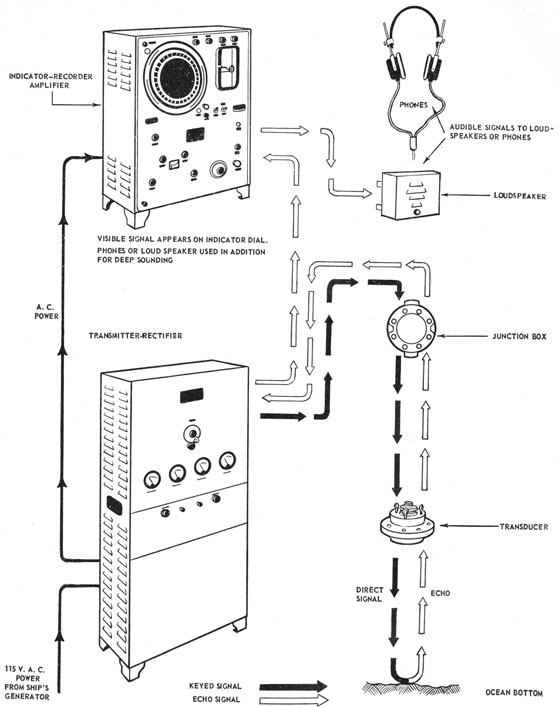
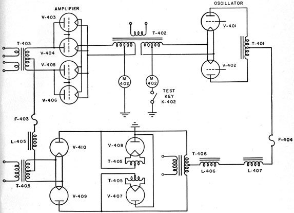
Figure 15-6 shows the complete schematic
diagram of the NJ-9 equipment. The illustration
shows that the NJ-9 uses a separate projector
and hydrophone.
There are three units and a motor-generator
set in the NJ-9 system. Because the indicator-recorder used in the NJ-9 system is the same as
that used in the NMC-2, it is not discussed
further at this time. The other two units are the
transmitter-rectifier and the receiver-amplifier.
TRANSMITTER-RECTIFIER UNIT
The transmitter-rectifier unit may be divided
into three major electric circuits-(1) rectifier,
(2) keying, and (3) discharge.
The transmitter functions through the charging
and discharging of capacitors. The discharge from
one of these capacitors produces ionization within
the discharge tube, which then becomes conductive
and discharges the power capacitor through the
transducer.
When power transformer T401 (figure 15-6) is
energized with 115 volts of alternating current
the rectifier circuit closes after a 30-second delay
introduced by relay K401. This delay permits
the cathode of rectifier V402 to come up to operating temperature. The a-c power is converted
into high-voltage direct current, which immediately charges capacitor C403. The power-output
capacitor, C404, also is charged by this high
voltage through resistor R402, which introduces a
time constant of 0.02 second. Simultaneously,
capacitor C401 is charged through resistor R401
and is discharged through the primary of transformer T402 when the keying contacts of the
indicator close. The discharge of current through
the primary of transformer T402 is stepped up
on the secondary of the transformer to a high
voltage, which causes the argon discharge tube,
V403, to ionize.
When ionization takes place, the gas in tube
V403 offers a low-resistance path for discharging
capacitor C404. Capacitor C404 is connected in
series with the transmitting projector, and its
discharge current must pass through the winding
on this projector. Because the resistance of the
total discharge path is small, a heavy current flows.
This current causes the tube to flash a brilliant
bluish-white light.
Immediately after discharging, capacitor C404
acts as a short circuit on the discharge tube, which
deionizes because there is insufficient potential
across the tube to maintain ionization. Capacitor
C404 then is charged from the high-voltage supply
and is discharged when the indicator-keying contacts close. This cycle of charging and discharging
capacitor C404 is repeated approximately 120
times per minute when the fathoms-keying contacts are operating and 720 times per minute
when the feet-keying contacts are operating.
RECEIVER-AMPLIFIER
The receiver-amplifier consists of (1) two stages
of amplification (V101 and V102) tuned to the
frequency of the projector, (2) a detector (V103),
and (3) an output stage (V104). A milliammeter,
M101, at the front of the unit indicates the anode
current of the output tube and thus provides a
check on the operation of the unit. A bias adjustment, R109, operated by means of a screw driver,
controls the detector bias and thus the minimum
signal level. A power supply, including rectifier
tube V105 and its filter system, provides d-c voltages for the anodes and a low a-c voltage for the
tube heaters.
PROJECTOR AND HYDROPHONE
The projector and hydrophone are of the magnetostriction type, and each of them consists of an
assembly of nickel laminations with an electric
winding. The transmitting projector has a low
impedance with only a few turns in the winding,
whereas the receiving hydrophone is of much
higher impedance and has a correspondingly
greater number of turns. The frequency of the
projector is controlled by its natural period, which
is approximately 21.6 kc.
NK-7 Sonar Sounding Equipment
GENERAL
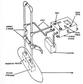
The NK-7 sonar sounding equipment is portable
and is designed to operate from a 6-volt battery
in boats in which no permanent echo-sounding
installation can be made and where the depth to be
recorded does not exceed 200 fathoms. The
general arrangement of this equipment is shown in
figure 15-7.
The NK-7 system is essentially the same as the
NJ-9 system, but the NK-7 transmitter power
Figure 15-7. -Pictorial diagram of the NK-7 sounding
equipment.
output is not so great. The NK-7 has no visual
depth indicator, only a recorder. The projector
and hydrophone are of the same type as those used
in the NJ-9 equipment. A schematic diagram of
the complete NK-7 unit is shown in figure 15-8.
RECORDER
S101 is the main power switch. Because of the
mechanical arrangement of the main switch, successive turnings alternately close and open the
circuit. This switch also reverses the polarity for
motor B101 but retains a fixed polarity for the
chart lights, vibrapacks, and tube filaments. A
specially designed cam attached to the chart feed
roll operates switch S105, which keeps reversing
the polarity of the input leads to the motor. This
action prevents deterioration of the governor contacts caused by electrodeposition of metal from
one contact to another. As a result the contacts
wear evenly.
This polarity-reversing operation does not affect,
the direction of stylus rotation, because the field
and armature currents of B101 are both reversed
simultaneously. The speed of motor B101 is
closely controlled by the centrifugal motor governor. Contacts B101A of this governor are closed
normally when the motor is stopped or is running
slowly. As the motor speed increases beyond the
correct value determined by the adjustment of the
speed control, the contacts open because of centrifugal force. This action places resistor R101
in series with both the field and the armature of
275
Figure 15-9. -Units of AN/UQN-1B sonar sounding set.
the motor, thus limiting the flow of current and
slowing down the motor.
As the motor continues to slow down, the contacts close; resistor R101 becomes shunted; current
increases through the armature and field; and the
motor speeds up. Thus, by action of these contacts, the motor attains the correct speed of 4,026
revolutions per minute. The speed-control knob
permits adjustment of the motor speed by changing the spacing and tension of the governor contact
mechanism. Capacitor C103 limits sparking of
the governor contacts, which prevents interference
with radio reception. Switch S106 is connected
mechanically to the feet-fathoms lever. This
switch is opened only when the lever is in the
middle position. This operation cuts down the
current to the motor by shunting the supply
through resistor R102, and the motor slows down.
This slowing action allows easy meshing of the
gears when shifting from feet to fathoms.
When closed, the direct signal switch, S102,
permits direct coupling between the transmitting
element and the amplifier through capacitor C101.
This coupling allows the emitted signal to be recorded immediately on the chart. This recorded
transmitter signal is the zero mark. Motor B102
operates the blower, which provides forced ventilation for the recorder case.
Transmission of Signal
The electric power for energizing the magnetostriction transmitter is obtained from the 300-volt
d-c output of vibrapack D101, which charges
capacitor C104 through resistor R103 while the
keying contacts, E103 and E102, are open. R103
is a current-limiting resistor inserted to prevent
overloading the vibrapack. At the instant contacts E102 and E103 close, capacitor C104 discharges through the windings of the transmitter
causing it to vibrate at its natural frequency of
about 21 kc. This emitted signal occurs once
each revolution of the stylus arm, at the point of
zero marking on the chart.
Reception of Signal
In normal sounding, the echo is picked up by
the receiver element and, after passing through
the amplifier, is led to the stylus assembly in the
form of high-frequency alternating current at
about 300 volts. This voltage discharges through
the chart and ground and thus produces the depth
record. Resistor R104 limits the current through
the stylus needle.
VIBRAPACKS
Power from the 6-volt storage battery is applied
to vibrapacks D101 and D102, which in turn provide approximately 300 volts d-c. The output of
the vibrapacks supply both the screen and plate
circuits for the amplifier tubes. As mentioned
previously, D101 also supplies electric power
for energizing the magnetostrictive transmitting
element.
These power units are complete assemblies. In
vibrapack D102 a rapidly vibrating reed interrupts the 6-volt circuit through the primary of
power transformer D102H and produces a pulsating direct current. A high-voltage alternating
current is thus produced in the secondary. This
current is rectified by a mechanical synchronous
rectifier arrangement in the vibrator. Choke
D102A and capacitor D102D provide a filter for
the high voltage inside the vibrapack. Choke
D102B and capacitor D102C prevent the ripple
voltage from feeding back to the 6-volt line, thus
preventing interference.
The operation of D101 is the same as that of
D102. The output from both vibrapacks is filtered still further by capacitors C137 and C138.
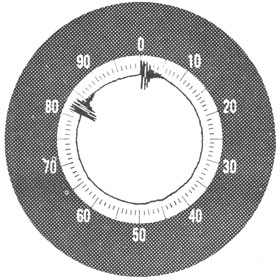
Figure 15-10. -Typical presentation on CRT indicator.
277
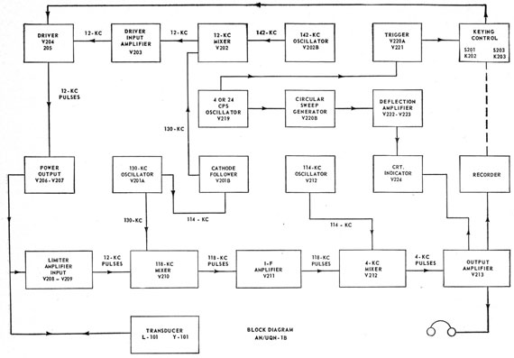
Figure 15-11. -Block diagram of AN/UQN-1B.
The vibrating elements are enclosed in a metal
tube having an internal sponge-rubber support,
which reduces vibrator noise and insulates the
elements from the metal case. Because the metal
tube is spun on to a special multiprong plug-in
connector, the contacts are not accessible for
cleaning or adjustment. If defective, the vibrapack must be replaced with a spare.
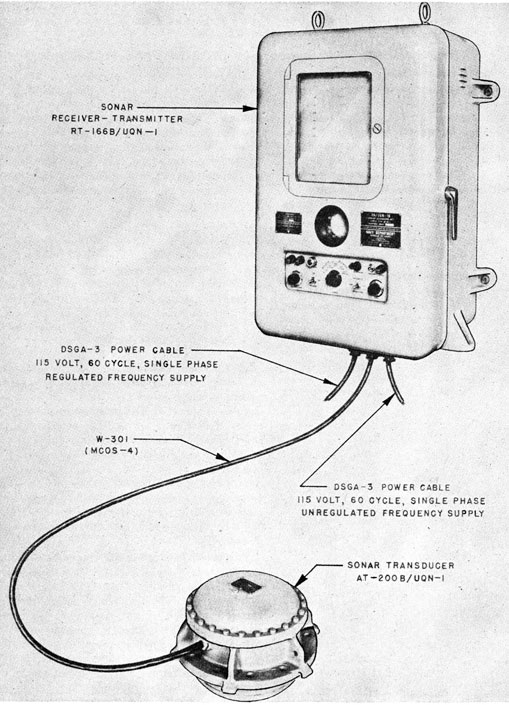
AN/UQN-1B Sonar Sounding Set
The AN/UQN-1B is one of the most modern
types of sounding equipment being installed on
ships today. In contrast with the old types of
equipment, the AN/UQN-1B comprises only one
small unit with its associated transducer. A
photograph of the entire equipment is shown in
figure 15-9. In spite of its small size, it gives
very accurate readings, at a very wide range of
depths, from about 5 feet to 6,000 fathoms.
The equipment is designed for installation on
either submarines or surface vessels for the purpose
of measuring and either indicating or recording
water depths. Three recorder ranges are
provided-0 to 600 feet, 0 to 600 fathoms, and 0 to
6,000 fathoms. Two indicator ranges are provided-0 to 100 feet and 0 to 100 fathoms. Means
are provided for transmitting a single ping or for
automatically keyed operation. The equipment
operates by emitting a pulse of ultrasonic energy
into the water and measuring the time required for
the pulse to travel to the bottom and return.
When recording, a stylus starts across the recorder chart simultaneously with the emission of
the pulse. The stylus moves at a constant velocity and marks the paper twice-once at the top of
the chart when the pulse is transmitted and again
278
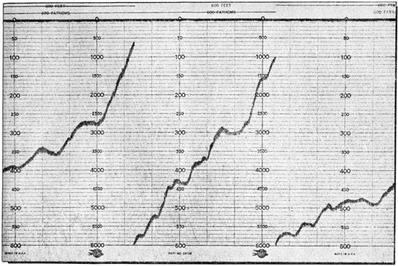
Figure 15-12. -Typical AN/UQN-1B depth recording.
when an echo returns. This procedure provides
two points spaced in proportion to the depth of
water beneath the transducer. Visual indication
is provided by a circular sweep on the face of a
cathode-ray tube (figure 15-10). The transmitted
pulse and the returning echo radially modulate the
trace. An engraved translucent shield in front of
the CRT furnishes a scale. The transmitted pulse,
which always occurs at zero on the scale, and the
echo appear as small radial bars across a luminous
circle. The uniform angular velocity of the trace
provides the desired time-depth relationship.
The mode of operation is selected by use of the
appropriate controls on the front panel of the
equipment.
The transducer comprises an array of ammonium dihydrogen phosphate (ADP) crystals in a
pressure-tight, flanged housing. It is designed
for flush mounting in a standard hull ring of the
bottom plating of a surface vessel or outside the
pressure hull of a submarine. A tuning inductor
is mounted inside the housing. This inductor,
with the capacity of the crystals, forms a series-resonant circuit at 12 kc.
The dimensions and arrangement of the crystals
and a monel backing plate produce maximum
energy transfer at 12 kc.
There are no tuning controls on the equipment
because all of the oscillators are crystal-controlled,
and all frequencies are fixed. There are three
oscillators that provide basic frequencies of 114,
130, and 142 kc. A fourth oscillator provides
either a 4- or a 24-cps frequency to supply the
circular sweep generator. These oscillators are
shown in the block diagram in figure 15-11. From
the three basic frequencies, the following resultant
frequencies are obtained:
1. 12 kc (142-130 kc) for transmitter operation.
2. 118 kc (130-12 kc) for receiver i-f operation.
3. 4,000 cps (118-114 kc) for chart marking,
CRT modulation, and listening.
279
The transmitter delivers 800 watts of pulsed
12-kc power through a transmission line to the
transducer. The transmitter is a series of transformer-coupled amplifier stages consisting of a
single-ended input amplifier (V203), a push-pull
driver stage (V204 and V205), and a class B,
push-pull, power-output stage (V206 and V207).
Transmitter input voltage is constant; keying is
accomplished mechanically for recording and with
a triggered gas tube for indicating by completing
the cathode circuit of the drive tubes, input amplifier, and 130-kc cathode follower.
The receiver takes its input from the 12-kc
transmitter pulse, and mixes it with a signal from
the 130-kc oscillator, V201A, and the resulting
difference signal of 118 kc is used as the i-f frequency. This 118-kc signal is amplified and
mixed with a 114-kc signal to produce the 4,000-cps audio frequency.
The recorder is conventional and has three
ranges. An actual recording sheet of this equipment is shown in figure 15-12. This equipment
will perform well at any depths encountered.