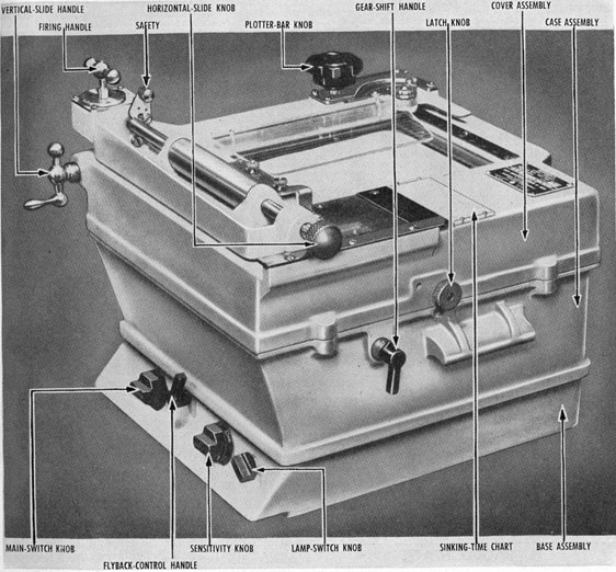
The tactical sound-range recorder is a dual-purpose device, designed (1) to print electrically
a graphic chart of the impulses that are received
from an echo-ranging sonar equipment, and (2) to
determine from such a chart the proper time for
firing the underwater ordnance. (See figure 12-1.)
The echoes are recorded so that the slant range of
a submerged object upon which the transducer is
trained may be read directly from the chart. To
achieve this function, the recorder must key the
sonar transmitter.
The recorder has the following basic features:
1. A strip of electrochemically sensitive paper
that moves at a constant speed from top to
bottom of a rectangular viewing window on
the front or top of the recorder.
2. A mechanism that causes a reciprocating
carriage to traverse periodically and at constant linear speed across the chart in a left-to-right direction, perpendicular to the motion of the chart.
3. A contact member, fixed to the reciprocating
carriage, for closing a circuit so as to cause
momentary energizing of the sonar transmitter shortly after the carriage begins its
constant-speed traverse.
4. A stylus, attached to the reciprocating carriage, for electrochemically marking the chart
when sound is being transmitted or received.
5. A speed-changing device (gear changer) that
provides two chart and two stylus speeds and
therefore two maximum range scales.
Details of the range recorder vary for different
models. In general, however, the basic principles
are as explained in this chapter.
CHART DRIVE
A supply roll of moist, sensitized paper is contained in a vapor-tight tank to minimize evaporation and is withdrawn from the tank between a
sponge-rubber gasket and a stainless-steel roller.
The chart is gripped at the rear of the paper drive
by two feed rollers, which draw it across the top
of the tank unit. The feed rollers are coupled by
means of a positive-drive spring clutch through a
suitable gear box to a synchronous motor, thus
providing constant linear speed of chart motion.
A third roller, which collects the used paper record,
is geared to the feed rollers through a friction
clutch.
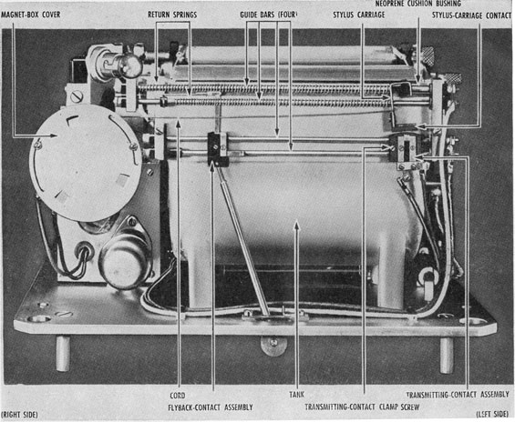
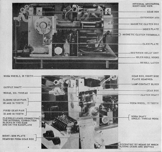
Guide bars for the reciprocating carriage are
mounted at the supply end of the chart drive.
(See figure 12-2.) This carriage is drawn from the
left to the right of the instrument by a cord that is
wound on a pulley. The pulley is rotated by a
magnetic clutch, which is driven by the synchronous motor that actuates the chart drive. During
its travel the carriage compresses two light helical
springs, which, when the magnetic clutch is de-energized, restore the carriage rapidly to its starting
point at the left of the recording paper.
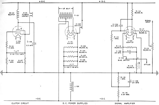
MAGNETIC CLUTCH CONTROL
The current through the magnetic clutch is controlled through a gas tetrode. (See figure 12-3.)
A conventional vacuum-tube rectifier supplies a d-c
voltage, the positive side of which is connected to
one terminal of the clutch. A 2,000-ohm resistor
from the cathode of the gas tetrode completes the
circuit to the negative side of the line or ground.
When the gas tube is conducting, the current
228
Figure 12-1 -Tactical range recorder.
through it also actuates the magnetic clutch. A
small capacitor, 0101, connected to the cathode of
the tube is grounded through a 1-megohm resistance. The control grid of the tetrode is connected
through a 5-megohm resistance to the capacitor
side of this grounding resistor. While current is
flowing through the tube, the grid assumes the
potential of the electric field at the grid, which is
approximately 100 volts positive.
Current flows through the high-resistance combination, and a potential of approximately 80
volts develops across the small capacitor with the
polarity indicated. If, by some device the tube is
deionized, the cathode drops to ground potential
and the high-resistance side of the capacitor is
therefore at a potential that is well below ground.
The net result is that a large negative bias is
applied to the control grid and the tube does not
fire when anode voltage is reapplied until the
capacitor discharges through the 1-megohm
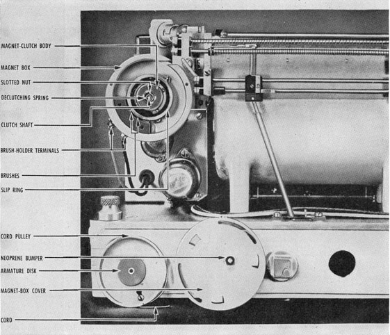
grounding resistor. Figure 12-4 shows the
magnet box with cover and pulley removed.
229
Figure 12-2 -Top view of the internal mechanism of a tactical range recorder.
FLY-BACK CONTACTS
Attached to the stylus carriage is a contact
member that serves a dual purpose-(1) to key the
transmitter shortly after the carriage starts its
motion from left to right and (2) to arrest the
carriage motion by wiping across the fly-back
contacts. At the right of the transmitting contact
assembly is a fly-back con tact assembly (figure
12-2), the position of which may be varied from
left to right by an external control.
In the course of its travel, after keying the
transmitter, the stylus carriage contact establishes
a circuit through the fly-back contacts, which are
connected to the cathode of the gas tube and the
positive d-c supply voltage. The stylus carriage
contact, therefore, short-circuits the gas tube and
magnetic-clutch combination, thereby de-energizing the clutch and deionizing the gas tube (figure
12-3). This action releases the cord pulley so that
the carriage is restored to the left by the return
springs. The moment the stylus carriage contact
disconnects the cathode from the positive line, the
cathode drops to ground potential and the control
grid swings negative. The clutch therefore remains de-energized until the potential on the
capacitor is reduced to the point at which the tube
fires. When the tube fires, the clutch is re-energized, thereby starting the carriage again on its
left-to-right excursion. This adjustable contact
230
Figure 12-3 -Schematic diagram of the tactical range recorder.
structure serves as a means of arresting carriage
motion at any desired point in its course across the
chart and is therefore called the fly-back contact.
An important result of this method of interrupting carriage motion is that the rate of keying is
not strictly synchronous. The duration of time
between (1) interruption of the stylus carriage
motion, as caused by the fly-back contact, and (2)
starting of the new pulse, is a function of the rate
of decay of the charge on the grid capacitor and
of the system voltage. This time delay is not
necessarily a constant. Furthermore, the length
of time during which the carriage moves from
left to right is rigidly a function of the position of
the fly-back contact. The rate of keying may,
therefore, be increased by moving the fly-back
contact to the left and be decreased by moving it
to the right. The maximum range that may be
observed on the chart is of course the maximum
possible travel of the stylus.
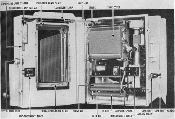
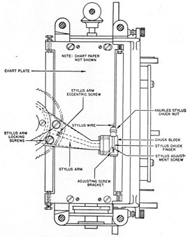
STYLUS ACTION
Attached to the top of the carriage is a stylus
bearing upon the chart directly above the roller
over which the chart issues from the tank. (See
figure 12-5.) The driving pulley cord is affixed
to the carriage so that the pressure of the stylus
on the paper is increased on its left-to-right, or
recording, motion. The guide bars on which the
stylus carriage slides are insulated from the tank
structure and are connected to the output of the
signal control circuit, which is actuated ultimately
by the receiver. The other side of the signal circuit is connected to ground, so that an audio signal
produces a current which passes from the stylus
through the paper to the tank cover roller, or
ground. When the current passes through the
chemical, the chemical becomes a permanent dye
at the point directly under the stylus. The record, then, is a series of dark traces on the chart
opposite a scale, which indicates the distance to
231
Figure 12-4 -Magnet box with cover and pulley removed.
the object that returned the echo. The chart is
calibrated directly in yards. Reverberation and
random noise are correspondingly recorded, and
echo identification is facilitated by repetition of a
trace at a particular range. This visible "memory" of the output of the receiver amplifier is one
of the most useful features of the instrument.
SIGNAL AMPLIFIER CIRCUIT
Successful operation of the recorder by very
weak signals from the receiver is made possible
by a 2-stage signal amplifier (figure 12-3). The
input signal from the receiver is applied through
a sensitivity control potentiometer, R110, to one
grid of V103. The associated plate is resistance-coupled to the second grid of V103 which acts as
a cathode follower to supply the stylus signal.
An automatic signal biasing feature is incorporated in the cathode-follower stage. This feature
suppresses most of the reverberation and background impulses that lack the "solid" character
of a true signal. Directly in series with the cathode is a 24-μf electrolytic condenser, C106,
shunted by a 30,000-ohm resistor, R112. This
combination is in series with the stylus which is
shunted to ground by an additional 30,000-ohm
resistor, R113. The R112-C106 combination can
be shunted out by a bias switch, S103, when the
232
Figure 12-5 -Tactical range recorder with cover open.
biasing feature is not desired. The consequence
of the biasing arrangement is that an amplified
signal applied to the second triode causes the
potential of the cathode to rise as current flows
through the stylus. The charge developed on the
capacitor prevents further current flow unless the
cathode potential exceeds the charge remaining
on the condenser, depending on the time constant
of the RC combination.
The sensitivity control must be operated at
minimum gain to prevent overloading of the automatic bias circuit and loss of discrimination.
Under some operating conditions the biasing
feature must be cut out to get the highest sensitivity.
The resistor, R113, provides a sharp cut-off
for the marking sensitivity of the paper, which
has a nonlinear resistance. The paper has a low
resistance for strong currents but a high resistance
for weak currents. With R113, the total variation in resistance is less and the signal more uniform.
Without R113, faint signals would produce a very weak trace.
SPEED-CHANGING MECHANISM
The gear box between the synchronous motor
and the feed rollers and magnetic clutch is provided with a gear shift that changes the speed of
the chart in the same ratio as the speed of the
stylus. (See figure 12-6.) The maximum range
of the recorder is either 3,750 yards at the slow
rate of stylus travel or 1,500 yards at the fast
rate. This gear shift is actuated by a lever on
the outside of the case of the instrument and is
provided with a neutral position in which the
drive is disengaged. This neutral position is of
great importance in providing a standby position
for keeping the recorder available for immediate
use without wasting paper. If the instrument is
turned off it is necessary to wait approximately
15 seconds before the rectifier circuit becomes
operative.
233
Figure 12-6 -Orientation of motor gearing.
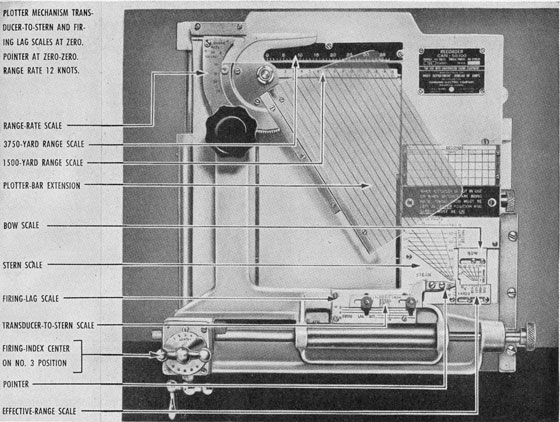
ANALYZER MECHANISM
The analyzer mechanism, which provides the
second of the two functions of the recorder, is
mounted as a unit on the cover casting. Its
essential component is a transparent plotter bar
pivoted on a casting which may be moved horizontally by a knurled knob. This casting is
mounted on another casting which may be moved
vertically by a crank. (See figure 12-7.) In
addition, the assembly of the plotter bar and the
horizontal casting may be moved horizontally by
the firing gear knob in five steps. Affixed to
this horizontal casting is a pointer, which is shifted
by the cranks with respect to data scales mounted
on the cover of the recorder. The position of
the pointer with respect to the horizontal slide,
and hence to the plotter bar, may be varied by
moving the pointer in accordance with (1) the
transducer-to-stern distance and (2) a selected
value of firing lag, or dead time. These latter
234
Figure 12-7 -Front view of the tactical range recorder.
adjustments are semipermanent and are not
altered in the course of an attack.
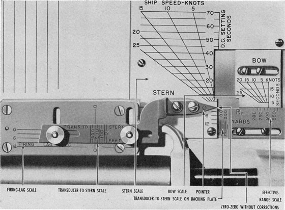
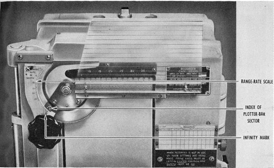
Another important feature of this plotter is the
two data scales on the cover of the recorder. (See
figure 12-8.) One, which is labeled stern introduces the proper correction for sinking time and
ship's own speed for a stern barrage if the pointer
is positioned with respect to the applicable data
on this scale. A similar scale, labeled bow, is
employed in an identical manner for introducing
the proper corrections in an attack with forward-thrown weapons.
RANGE-RATE PLOT
The horizontal motion of the stylus is uniform
and is scaled at one-half the velocity of sound so
that its excursion rate across the chart represents
800 yards per second. As the vertical motion of
the chart paper is geared at a fixed ratio with
respect to the stylus motion, the echoes that
appear on the chart form a range-rate plot. When
the range rate is zero the echoes form a vertical
line on the chart. When, however, the range is
closing, each successive echo is on the left of the
preceding one so that the leading edge of the
echoes form a sloping line. The slope of this
line can be translated directly into range rate in
knots. This translation is accomplished by a.
plotter bar, which is mounted on the analyzer
mechanism and pivoted at the zero point of the
range scale. When the plotter bar is pivoted so
that its slope is parallel to the slope of the echoes,
the range rate can be read from a semicircular
scale graduated in knots. This scale is located
at the top of the plotter bar (figure 12-9).
235
Figure 12-8. -Detail of correction scales.
BARRAGE TIMING
The combination of the analyzer and plotter
bar is designed to give the correct time to release
the ordnance. After the necessary adjustments
for ship's speed and setting of the depth charges
is made with the horizontal slide in the center, or
No. 3 firing position, the slide is translated to the
No. 1 firing position on the right by means of the
firing knob. When the line of echo traces is
observed-by the motion of the chart-to reach
the center of the plotter bar, the order is given
to fire the first charge. The knob is immediately
turned to the No. 2 firing position, and when the
traces again reach the center of the plotter bar
the second charge is fired. This procedure is
repeated until all the charges of the barrage are
released.
In an attack with forward-thrown weapons the
procedure is almost identical, the basic difference
being that the firing knob is not involved because
there is no spacing to the barrage. In short, the
analyzer is left with the safety on and with the
firing knob in the No. 3 position. When the echo
traces reach the center of the plotter bar the order
is given to fire.
Because the sound information available to the
recorder is always several seconds behind the
actual tactical situation, a shift in doppler may
indicate the recorder solution is inaccurate for
firing. Thus, the conning officer may fire sooner
or later than the recorder indicates. For this
reason the recorder's solution of time to fire is
called will to fire. The correct solution of the
problem of will to fire, as provided by this analyzer,
may be ascertained by a proper consideration of
236
Figure 12-9 -Plotter-bar index at infinity on the range-rate scale.
the following facts: Displacement along the direction of the chart motion may be represented as
time; displacement across the chart may be represented as range. Therefore the slope of any lines
with respect to these axes may be represented as
rate of change of speed. This correct solution
is obtained only if the mechanism is set up with
the firing knob in the No. 3 position and with the
recorder running at high speed (1,500-yard scale).
A safety lever normally keeps the instruments in
the No. 3 position and reduces to a minimum the
the chance for operator error.
Sound-Range Recorder
A range recorder that has as its only function
the determination of range is commonly called a
sound-range recorder instead of a tactical-range
recorder. Such an instrument is incorporated in
the OKA-1 sonar resolving equipment, previously
described. The keying and recording actions and
maximum range scales are the same as those of the
tactical recorder just discussed. The sound-range
recorder is housed in the top of the OKA-1 console
as shown in figure 12-10. The differences between
this recorder and the conventional tactical recorder
are shown by the following features of the sound-range recorder:
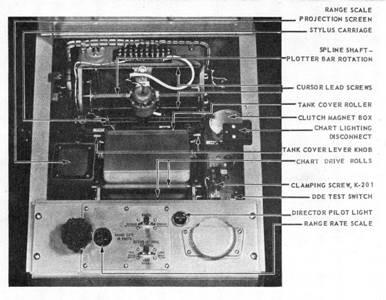
1. Determination of sound range is
239276°-53-16
accomplished by positioning an image of an optical
cursor that is projected on the recorder chart.
This optical cursor is actually driven by a synchro
system, positioned externally by the operator. In
addition to controlling the cursor, this synchro
system transmits sound range, Rq, to the various
computing circuits of the OKA-1.
2. Another control is provided to adjust the
cursor's angular rotation so that the slope of the
cursor image can be set parallel to the slope of the
incoming signal, which is by definition, range
rate, dRq. The angular position of the cursor is
used to drive a rate servo system which furnishes
an a-c voltage proportional to range rate, dRq.
237
Figure 12-10 -Top view of the OKA-1 slant-range recorder with cover open.
This range rate is transmitted to the depression-angle aided-tracking circuits.
3. The stylus drive motor of this recorder is
provided with a variable-speed motor to allow
adjustments to be made for the variation of the
speed of sound at different water temperatures.
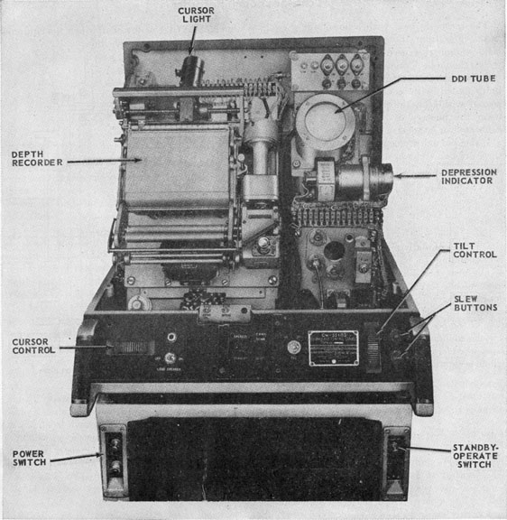
Depth-Determining Recorder
The QDA depth-determining equipment present s its solution on a chemical recorder that is
similar in principle-and to some extent in construction-to the tactical-range recorder. In the
depth recorder, however, the stylus travels at a
speed proportional to the sine of the target depression angle-the vertical velocity of sound, Vz.
The stylus can be said to move at a rate corresponding to the slope of the sound beam.
If the beam is steeply inclined the stylus moves
rapidly from left to right; if the beam is nearly
horizontal the stylus moves slowly. The ping is
transmitted just as the stylus moves away from
its zero position, and, at the instant the echo
returns, the stylus marks the recorder paper. For
a distant target the angle is small and, correspondingly, the stylus travels slowly but for a relatively
long period before the echo mark is recorded.
For a nearby target at the same depth, the angle
is relatively large and the stylus moves rapidly
for a short period before the echo mark is made.
Therefore, in both cases, the mark is recorded
at the same distance from the starting position of
the stylus. A linear depth scale, calibrated in
238
Figure 12-11 -Recorder and control console.
feet, extends across the recorder chart. The
stylus speed is controlled by the OKA-1 resolver,
but the basis of this speed is determined by the
QDA beam depression angle and the velocity of
sound in water. A movable layer depth contact
in the recorder makes possible a change in stylus
speed when a thermocline is reached.
A vertical cursor light can be moved across the
depth scale and aligned with the echo trace.
Geared to the cursor-light lead-screw is a synchro
generator which transmits the target depth information.
Figure 12-11 shows the recorder and control
console.
239
Echo-Sounding Recorder
The recorders used with echo-sounding equipment differ from those just discussed. Because
echo sounding is used in survey operations its
record should be permanent. Therefore, the paper
used for the record chart is of the dry type. It is
impregnated with conductive materials and is
coated with lead thiosulfate, which turns black
upon the passage of electricity. The paper is
calibrated in fathoms.
Instead of one stylus on a reciprocating carriage
there are two styluses, diametrically opposite each
other, on an arm that is center-driven in continuous rotation. (See figure 12-12.) When the
stylus moves onto the chart the transmitter is
keyed and the stylus marks the chart at the zero
position.
Later, when an echo is returned from the bottom,
the chart is similarly marked at the scalar position
corresponding to the water depth. When the
second arm rotates onto the chart another transmission-echo cycle occurs. As the chart is in
constant motion and the transmissions are close
together the picture on the chart is an elevation
plan of the ocean floor.
Echo-sounding equipments have two ranges-
shoal and deep. As it is essential to know later
which scale was being used, a third stylus prints a
line on the edge of the chart when the equipment
is operated in the deep position.