In this online version of the manual we have attempted to keep the flavor of the original layout while taking advantage
of the Web's universal accessibility. Different browsers and fonts will cause
the text to move, but the text will remain roughly where it is in the original
manual. We have not attempted to correct any errors found in the original document. However, this text was captured by optical character recognition and then encoded for the Web which has added new errors we wish to correct.
Please report any typos, or particularly annoying layout issues with the Mail Feedback Form for correction.
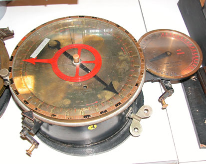
Below is a photo of a later version of a Vicker's Clock in the collection of the Clandestine Immigration and Navy Museum, Haifa, Israel. The differences are minor, the newer clock can have it rate changed without restarting.
The instrument has been designed as an adjunct to the range finders, its object being to show what range should be put on the gun sights at any subsequent interval, the rate of increase or decrease in the range, due to either the speed of the ship, the enemy, or both, having been ascertained by range finder and timing, or spotting, or the rate of change of range projector.
The instrument consists essentially of a dial face, a movable pointer, and a speed-adjusting index, and has a range of from 2,000 to 14,000 yards.
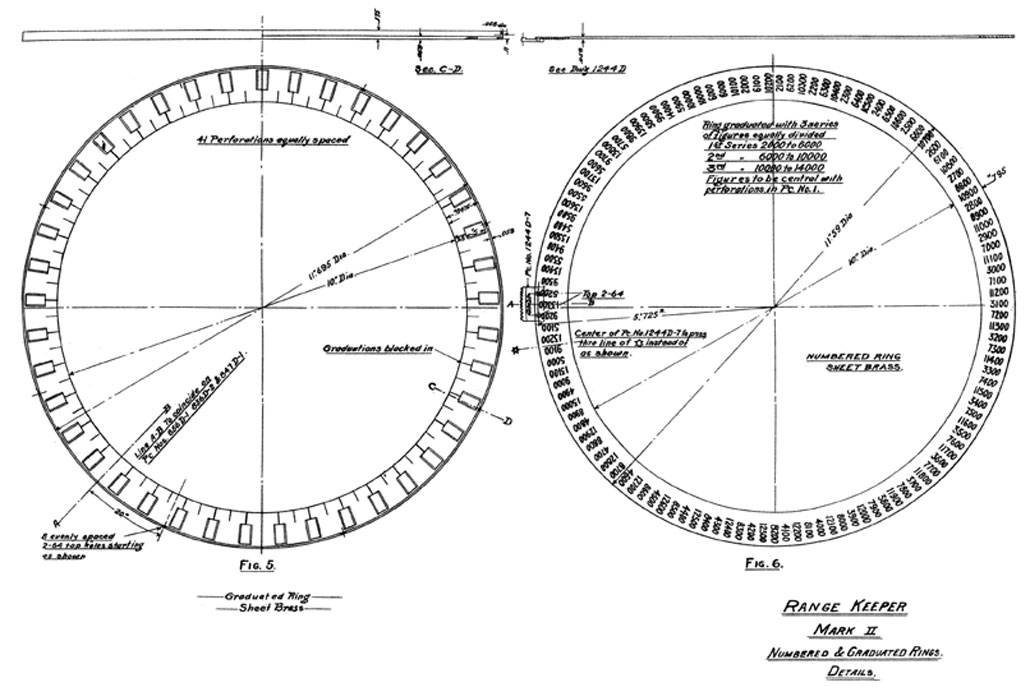
The range figures on the dial face are arranged in three series, i.e., from 2,000 to 6,000, 6,000 to 10,000, and 10,000 to 14,000. These are marked on a movable ring, but by means of perforations on the dial face only one series of figures will be exposed at a time; this arrangement insures a reasonably wide space between each pair of range figures and prevents confusion in reading, and also admits of divisions representing 25-yard increments being obtained. The change from one series of ranges to another can be effected without causing any error in the readings.
The pointer can be made to revolve either way at a rate corresponding to a change in range due to any speed between 38.6 and 1.5 knots or 2.3 and 60 seconds for 50 yards change of range; if there is no change in range, the movement of the pointer can be stopped.
The pointer will move either way according to whether the range is increasing or decreasing.
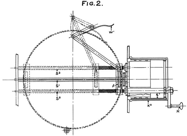
Figure 2 is a plan section showing the driving disk and friction roller; also the screws and gear by which the friction roller is traversed.
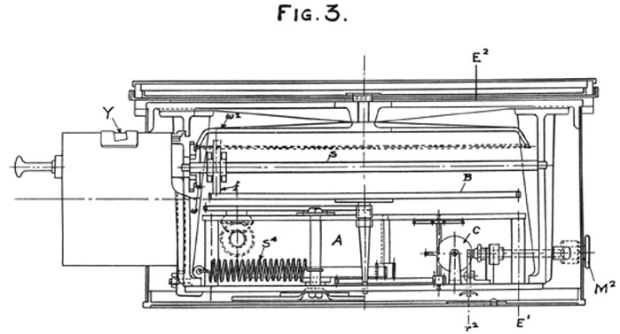
Figure 3 is a sectional elevation of the instrument.
The spring drum (A) and train of wheels is arranged to rotate the disk (B) at a constant speed, the speed being controlled by the fly governor (c). The friction roller (f) bears on the surface of the revolving disk and is caused to rotate thereby; the movement from the roller is transmitted by means of the central spindle (s1) and bevel wheels (w1, w2) to the pointer. By traversing the friction roller across the face of the disk the speed of the pointer can be varied from zero when in the center up to the maximum in either direction. The carriage for the friction roller is traversed by means of the screws (s2, s3) which can be rotated by the handle (H), at the same time rotating the sleeve (K1) and scale cylinder (K2), showing the rate of speed through the opening (Y) in the drum casing. The winding key is shown at M1 and the stopping and starting device is provided at M2.
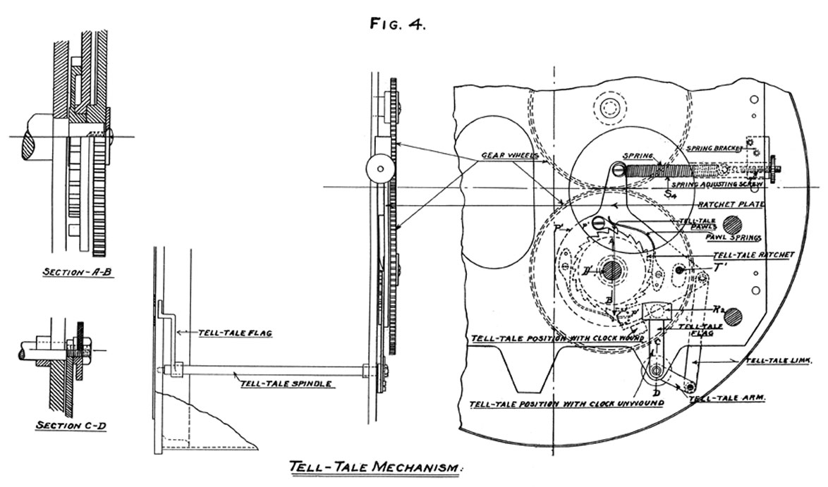
Figure 4 shows the arrangement of the rewind telltale. In this it will be observed that the ratchet wheel pawls (p1, p1) are mounted on a plate (P1) which has a slight rotative movement on the spring driving drum axis (D) and is limited in movement by means of stop (T1).
36584-14
2
A helical or spiral spring (S4) is attached to this plate, the result being that when the main driving spring is run down, and therefore weak, the spiral spring overcomes the turning effort of the latter and pulls the arm (R2) under the hole in the fixed portion of the dial plate. With this device rewinding will not cause the pointer to stop, so that the instrument need never be allowed to run down.
Compensating brake.-In order to maintain the load on the instrument as far as possible constant the compensating brake (W1) is fitted. This brake is arranged to be free when the pointer is traveling at its highest speeds and to bear with increasing load on the friction disk when the speed of the pointer approaches zero.
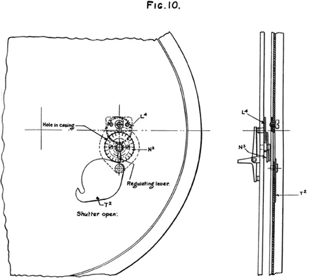
For adjusting the speed of the driving mechanism the movable shutter (T2) is provided in the rear of the casing (see fig. 10). This shutter permits access to the speed-adjusting device without removal of the rear cover. A mark in the form of a small dot has been made at the two extreme ends of the speed scale, and when either is brought under the cross line the correct speed of the pointer should be as near as practicable one revolution in three minutes, or more correctly between the ranges of 2,000 and 6,000 yards. The mean of the two extreme positions should be taken in timing the instrument.
Figures 5 and 6. The perforated ring (fig. 5) is fixed to the movable rim; the graduated ring (fig. 6) is situated below the former and is capable of being moved within its prescribed limits by the tangent screw.
The method of using the instrument is as follows:
The rate of change of range having been obtained by range finder and timing, or range projector, the instrument is set to that speed.
The distance having been obtained, the dial face is set with this distance opposite the pointer, and if the relative speeds and courses have been correctly assumed, and if the initial distance was correct, the pointer will continue to show the distance which should be put on the sight.
If the fall of the shot shows that too much or too little change in range is being applied the rate can be altered.
If the fall of the shot shows that the distance is incorrect, the perimeter of the dial is moved around until the correct distance is opposite the pointer; thus the pointer should always stand at the actual distance which is to be passed to the guns, and the range indicators, the telegraphs, and the gun sights should always agree.
3
CARE OF RANGE KEEPERS.
The range keepers have been made reasonably substantial, having regard to ordinary handling, but they should not be subjected to rough usage. They should, when not in use, be carefully protected from the weather.
The instruments if in general use should be overhauled, cleaned, and oiled, say, once in 12 months; no oiling or cleaning in the interval would appear necessary. The only parts which might require attention in the matter of lubrication and cleaning are the traversing screws and spindle for the friction roller. When oiling these, the clock should be suspended by the handle on the casing, so that any excess of oil would not fall on the surface of the driving disk, but into the lower part of the casing, and wiped clean afterwards. The screws should be wiped clean of surplus oil after lubricating, a piece of soft leather being used for the purpose.
When oiling the instrument, only the very best lubricant should be used for the purpose, and that very sparingly; a copious supply of oil indiscriminately poured into the instrument will completely disarrange the working, and should be avoided. It is also to be recommended that taking to pieces for examination purposes should be avoided, if possible, as great care is necessary in reassembling the parts to insure satisfactory working. It will be found sufficient under ordinary circumstances for examination and cleaning to remove the rear cover plate, the perimeter and dial rings, and the fixed plate of the dial. The whole interior of the mechanism will then be seen, and can be examined, and no further parts of the mechanism should be disturbed unless absolutely necessary.
To obtain a large variation of speeds from the instrument, it has been necessary to adopt a system of friction drive which renders the action extremely delicate, and care should be taken to prevent oil being used in such a quantity as to spread on to the surface of the driving disk, thus causing the working to be unreliable. In the presence of the oil the frictional resistance between roller and disk is greatly diminished, causing thereby a tendency to slip between the two parts, and thus give rise to error in the range readings for which the instrument has been set.
If required to further dismantle the instrument, the driving mechanism can be taken out , bodily by removing the screws fixing the rear check plate to the side frames, care being taken to first disconnect the stopping and starting handle, the link connecting to the "rewind telltale," and also the winding key. The parts of the knots drum should not require oiling except when the clock is being overhauled; this portion of the mechanism can only be dealt with by removal of the outer casing of the drum. In replacing this part care should be taken that the pinion operating the scale cylinder should correctly engage with the toothed rack of the latter, so that the speed of the pointer in either direction, when the speeding dot at either end of the scale is under the cross wire, should be the same in each case.
4
The clock is fitted with a winding key which has been arranged in such a manner that if wound in the wrong direction the key will simply unscrew. The instrument should be wound up when white disk appears, the key being turned to the right to wind.
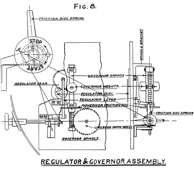
The speed-regulating device is shown in figure 10. The shutter T2 is shown in the opened position exposing the speed-regulating lever. By moving this lever in the direction toward the letter "S" the speed of the clock is decreased, and if moved in the opposite direction toward the letter "F" the speed is proportionately increased. The letters "F" and "S," denoting "fast" and "slow," are clearly marked on the dial plate "N3." A series of small notches are formed on this plate, as shown, in which the tail of the regulating lever is arranged to engage. Moving the lever one notch in either direction will change the rate approximately one second for one revolution of the pointer at the normal maximum speed, i.e., one revolution in three minutes.
When adjusting the speed of the instrument, it is desirable to work at the highest speed. A mark in the form of a dot has been made at the two extreme ends of the speed scale, and when either is brought under the cross line the correct speed of the pointer should be as near as practicable one revolution in three minutes, or, more correctly, over a range of 4,000 yards. The mean of the two extreme positions should be taken in timing the instrument.
The mechanism of the range keeper is simple, and it is suggested that at the first indication of failure to properly function, a competent mechanic take apart the range keeper so failing, and thoroughly examine it. There are no very delicate parts, and it can readily be seen just how all parts are designed to work.
The starting and stopping milled head (lower left side) should be turned, either to start or stop the range keeper, briskly. The milled head operates a friction spring which presses against the periphery of a small wheel. This wheel, through gears, is connected to the governor of the range keeper, and if the friction spring is eased down or up the inertia of the governor cylinders may not be overcome. In case of a failure of this mechanism to work, a very slight adjustment of the spring, readily made by a careful mechanic, will enable it to work.
It may be found that the range keeper will not start promptly when lying in a horizontal position. If it is permanently installed in an angular or vertical position, probably no trouble of this sort will result; but should it be found necessary to install it in a horizontal position, and a failure to start (most likely to occur at low speeds) result, the range keeper should be tilted up to an approximately vertical position, when it will start readily.
The crank on the right side of the range keeper, which actuates the drum upon which the rates of change of range are indicated, should be moved cautiously as the ends of the scales are reached; that is, as one approaches 40 knots, increasing or decreasing; for, if the drum is brought up abruptly against its stops the gear wheels on the shaft of the drum are apt to become misplaced, requiring a new adjustment. There is no danger of breakage in this connection, but in the drills the range keeper man should be cautioned against bringing up too hard against the stops. Should the handle have been forced beyond the limit of readings of . the scale, it can be reset by bringing the limit line on the drum to the reading line on the window, then holding the handle rigid. Loosen the nut securing the handle, and if the range on the range scale is increasing, turn the handle in that direction until it comes to a stop, then tighten the nut. If the range on the scale is on the decreasing side, proceed as above, changing the direction of rotation of the handle.
Should it be found that, as a result of transportation, the range keeper does not function properly, it should be put in a vertical position, set at the highest rate of change of range per hour, and allowed to run a while. Should it run too fast or too slow, the regulator under the
5
sliding plate on the bottom of the case can be readily adjusted, and its effect will be promptly shown.
It may be found that a failure to start promptly is due to the pointer resting against the dial. This can best be remedied by removing the glass face and springing the pointer.
The motion of the pointer is due to the friction between the periphery of a wheel and the sand-blasted surface of a metal disk. Should the pointer hesitate, quiver, or stop temporarily during its rotation, it may be found that a foreign substance, a drop of oil, etc., is on the wheel or disk.
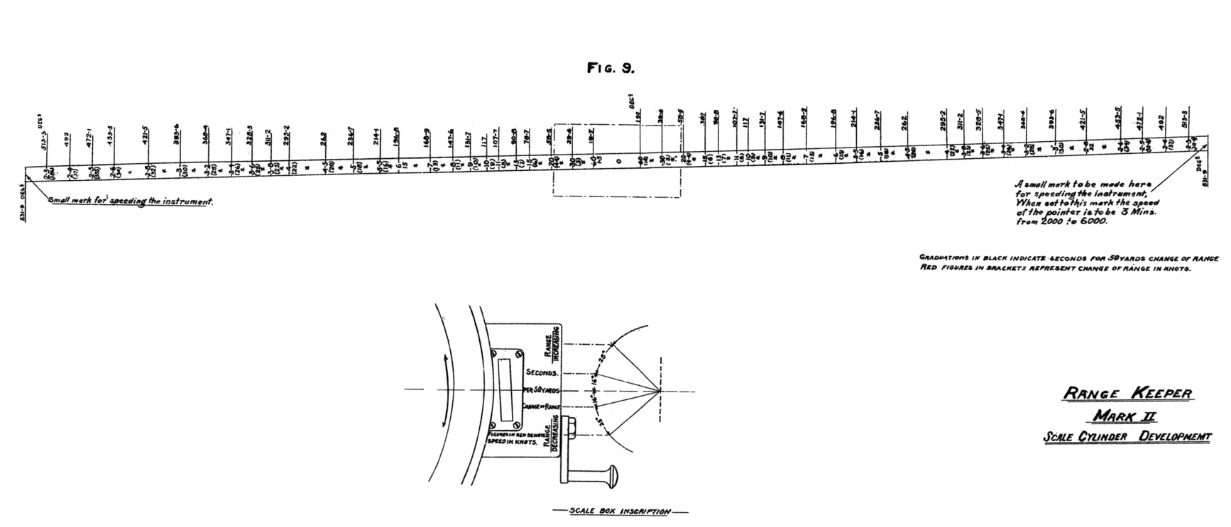
It should be noted that the "seconds per 50 yards change of range" indicated in black figures on the drum at the right of the instrument are approximations only and are for the rapid use of the range keeper man.
The white telltale may appear in the hole on the face of the range keeper above "Rewind when telltale appears" before the range keeper is run down. The adjustment for this is easily made by slackening up on the tension of the spiral spring on the bottom of the range keeper. Simply reverse the entire case, remove the bottom, and slack up the set nut on the screw eye carrying the end of the spring.
Set up on the same nut if the telltale appears too late.
The method of using the instrument is as follows: The rate of change of range having been obtained by change of range projector, by range finder and timing, or guessed, the instrument is set to that speed or time interval for 50 yards change.
This instrument is also a change of range finder, if used in conjunction with a range finder.
If successive observations are taken with the range finder, and the speed handle is worked so as to make the pointer indication agree with the range by range finder, then the rate of change of range is obtained.
In this pattern of instrument the best way of applying the spotting correction is to work from one of the lines on the plate.
Great care must be exercised in changing from one series of ranges to the other not to shift the whole perimeter relative to the pointer. The ranges are in three series, 2,000 to 6,000, 6,000 to 10,000, 10,000 to 14,000.
When starting the instrument, it is better to put it at a high speed of change of range.
Ο
SPECIFICATIONS FOR THE MANUFACTURE OF RANGE KEEPERS,
MARK II, FOR THE U. S. NAVY.
DRAWINGS AND SPECIFICATIONS.
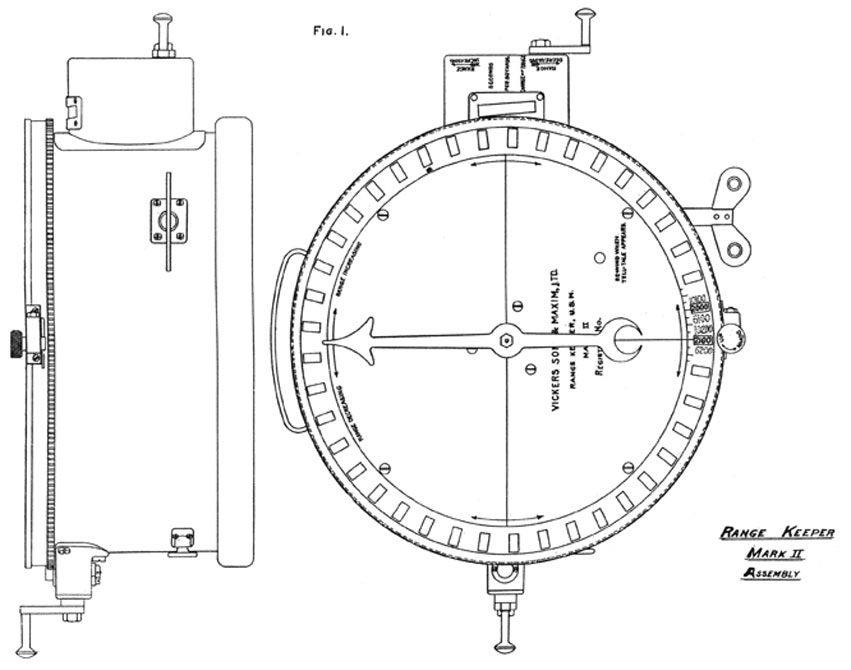
1. Description of drawings.-A complete set of working drawings on tracing cloth, with figured dimensions showing accurately the design and construction of all parts of the range keepers manufactured under these specifications, shall be furnished by the contractor's, together with a description giving the nomenclature of all parts and instructions for handling, adjusting, and caring-for them, before submitting any range keepers for final test.
INSPECTION.
2. Inspection.-The inspection and tests hereinafter specified shall be made at the place of manufacture in the presence of an inspector selected by the Bureau of Ordnance.
3. Time of inspection.-When a lot of not less than ten range keepers is ready for inspection, the contractor shall notify the Bureau of Ordnance in order that an inspector may be sent. The number of range keepers in excess of ten which shall be inspected at any one time shall be mutually agreed upon by the Bureau of Ordnance and the contractor, the object being to prevent, the inspection interfering with rapidity of manufacture and delivery.
4. Expense of tests and instruments used.-Except as hereinafter provided, all tests, measurements, etc., shall be made at the expense of the contractor, under the observation and supervision of the Bureau's inspectors, and with the contractor's gauges and instruments. The inspector has the light to verify all testing or gauging instruments at any time during which they may be in use by him for inspections of work or material.
5. Burden of proof.-The obligation is upon the contractor to satisfy the inspector as to the correctness of everything and its accordance with the terms of the contract.
6. Contractor to inspect work first.-All machined work must be examined by the agents of the contractor for workmanship and material, and found to be up to the contract standard before it is submitted to the inspector.
7. Bureau may use its own instruments.-Lots of machined work shall be submitted with the gauges and instruments used in the contractor's inspection, and, if these are not satisfactory, the Bureau of Ordnance may provide (at its own expense) and use any other gauges and instruments that it may see fit.
8. Condemned material.-Material or work condemned by the inspectors shall not be embodied in the articles to be furnished the Bureau of Ordnance.
9. Contractor to assist inspectors.-The contractor at all times shall render such assistance to the inspectors as the latter may require in the prosecution of their duties as they understand them.
10. Reference to Bureau.-The inspector is to decide, in the first instance, at to the results of all official tests, but if he is in doubt he may refer the matter to the: Chief of the Bureau of Ordnance.
2
11. Inspection marks.-Range keepers which have passed inspection by the inspector shall be marked as follows: "Range keeper, Mark II", followed by the initials of the inspector.
12. General description.-The instrument is essentially a clockwork mechanism capable of operating at any desired speed in either direction from 0 to the maximum speed desired. It is intended as an adjunct to the range finder and range projector, its object being to show what range should be put on the gun sights at any subsequent interval, the rate of change of range having been ascertained and the range keeper adjusted for the corresponding speed. Practically the conditions for which provision must be made are as follows: In battle two vessels may be approaching each other or receding from each other at any rate between 0 knots per hour to about forty (40) knots per hour (22.52 yards per second). The distance between the vessels at any instant and the rate at which this distance is changing having been determined, it is practicable to determine the distance between the vessels at any subsequent instant by simply applying a correction to the first distance obtained by multiplying the change in distance per second by the elapsed time. In practice what is desired to know is the instant at which the distance changes by a certain amount and the work desired of the range keeper is when set for the original range and, for the determined rate of change of range to indicate the actual range at any subsequent time and the times at which the range changes 50 yards. This to be done when the range is either increasing or decreasing.
The indications desired shall be shown as follows: The face of the instrument shall be a clock dial marked in ranges from 2,000 yards to 14,000 yards at 50-yard intervals. These markings can be in three or four series, but only one series shall be visible at one time. A revolving pointer actuated by the mechanism shall point to the range on the dial face which is to be indicated. This pointer shall move to the right while the range keeper is indicating a series of increasing ranges and to the left while indicating a series of decreasing ranges.
The graduation ring shall be so arranged that any range within the limits specified can be brought opposite to the pointer in any position of the latter. This shall be accomplished by a gearing actuated by a crank, and the gearing shall be of such a character and so arranged that one turn of the crank shall move the indication carriers through an angle corresponding to a change of range of 50 yards with the pointer in a fixed position, and the crank shall turn to the right for bringing a higher range opposite the pointer and to the left for bringing a lower range opposite the pointer. This gearing shall also be so arranged as to make it possible to throw out the gearing and move the indication carriers by hand, and the clutch which will permit of this shall be capable of being positively locked in either the out or in position and shall not depend upon friction between two surfaces for the transmission of motion.
The range keeper shall in addition be fitted, if found practicable after trial, with au indicator which shall display a visual signal each time the range changes 50 yards, this signal to indicate both the direction and amount of the change of range. The direction will be indicated by the word "up" for an increase and "down" for a decrease.
13. Adjustment.-The rate of the range keeper shall be capable of adjustment by the turning of a crank or handwheel. The index of the adjustment shall show the rate for which the range keeper is set in rate of change of range in knots (of 6,080 feet) per hour, as shown on drawing No. 811D (V. S. and M.). The crank or handwheel shall turn to the right for increasing the rate of change of an increasing range and to the left for increasing the rate of change for a decreasing range.
3
14. Tools.-The instruments shall be complete in all respects when delivered and a set of mounting and setting tools shall be furnished with each five range keepers supplied.
15. Materials.-The materials shall be of best commercial quality and the workmanship shall be of the highest clock maker's standard.
16. Strength.-The instruments shall be so constructed as to be able to withstand, without being thrown out of adjustment, the shock of discharge of all the guns of a battleship's broadside, the instruments being placed in a compartment underneath the protective deck near the base of a turret.
17. Time of running and method of winding.-The instruments shall be capable of operating for at least one hour without rewinding. The winding key shall be permanently attached to the range keeper in gear for winding, but the key shall not revolve, due to the operation of the mechanism.
18. Starting and stopping attachment.-The instruments shall be fitted with an attachment for starting and stopping the mechanism independent of the winding key.
19. Marking of indicators.-The indications of range and of change of range shall be as shown on drawings 811D and 856D (V. S. and M.).
20. Range of instruments.-The instruments shall be capable of indicating changes of ranges due to speeds ranging from 0 to 38.6 knots (of 6,080 feet) in either direction.
TESTS.
21. Each instrument before acceptance shall be subject to the following test, and a failure to comply with the requirements of the tests shall cause it to be rejected:
Each range keeper shall run for ten minutes at each of the following rates of change of range per hour, both increasing and decreasing: 6, 10, 20, 30, and 38.6 knots. The times during which the range keeper is running at the different speeds shall be accurately kept and the actual change of range which would occur at the rates for which the range keeper is set calculated. The change of range shown by the range keeper shall not differ more than five (5) per cent from the calculated change. During this test the range keeper shall not be stopped except when stopped while changing from increasing to decreasing ranges. Ten seconds will be allowed to make a change of rate.
22. Endurance test.-One range keeper to be selected by the inspector in every ten passing the tests prescribed in paragraph 21 shall be run for one hour at each of the following rates of change of range per hour: 6, 10, 20, 30, and 38.6 knots, both increasing and decreasing, and the change of range indicated by the range keeper for any hour shall not differ from the actual change of range due to the prescribed speed for that hour more than five (5) per cent of such actual change of range. In case any range keeper selected for this test shall fail to comply with the requirements thereof another of the same lot of ten shall be subjected to the same test, and this process shall be continued until one of the ten range keepers shall pass this final .test, when the range keeper passing the test and the remainder of the lot may be accepted without further test. Range keepers failing to pass this test on the first trial can be again submitted for test, but in that case each must pass both the ten-minute and one-hour tests.
23. Modification of tests.-The Bureau of Ordnance reserves the right to modify the tests and trials if experience demonstrates that such modification is desirable and necessary in order to safeguard the interests of the contractors and of the Government.
4
24. Waiving of tests.-The Bureau of Ordnance may waive any or all tests if it so desires.
25. Responsibility for performance.- No action of the Department or of the Bureau of Ordnance, or of its officers, agents, or representatives, as described herein, shall be construed as in any way relieving the contractor from the responsibility of producing thoroughly efficient and satisfactory range keepers and articles pertaining thereto, within the meaning and limitation of the contract.
DEFECTS.
26. Faults developed after acceptance.-Any parts of the range keepers which may, during the first year from date of acceptance, be found defective or showing symptoms of weakness, owing to faulty material or workmanship, shall be repaired or replaced by the contractors at their own expense.
27. Improvements during construction.-If during the manufacture the contractors should have any improvements to propose in any of the material contracted for the Bureau of Ordnance expects that, they will do so, with a view to making the range keepers as efficient as possible; but no change at all can be made in the types and details as herein specified unless approved by the Chief of the Bureau of Ordnance.
Approved.
N. E. MASON, Chief of Bureau.
BUREAU OF ORDNANCE, Navy Department, December 14., 1907.