This publication is RESTRICTED and will be handled in
accordance with Article 76, United States Navy Regulations, 1920.
2
NAVY DEPARTMENT
BUREAU OF ORDNANCE
WASHINGTON, D. C.
17 APRIL, 1944
RESTRICTED
ORDNANCE PAMPHLET 1171 (PRELIMINARY)
RANGEFINDERS MARKS 58; 58, MOD. I; 65; AND 65, MOD. I
1. Ordnance Pamphlet 1171 (Preliminary) describes Rangefinders Mark 58 and Mark 58, Mod. 1 used in Gun Director Mark 50, and Rangefinders Mark 65 and Mark 65, Mod. 1 used in exposed deck mount Rangefinders Mount Mark 65.
2. This pamphlet does not supersede any existing publications.
3. This publication is RESTRICTED and should be handled in accordance with Article 76, U. S. Navy Regulations, 1920.
G. F. HUSSEY, JR., Rear Admiral, U. S. Navy, Chief of the Bureau of Ordnance.
NOTE:-Rangefinder Mark 58 is described on pages 1 to 54 of this pamphlet. The photographs and text are equally applicable to Rangefinders Mark 58-1, Mark 65, and Mark 65-1 except for differences in the range conversion mechanism, the end box bracket assembly, and the auxiliary sight. These differences are discussed on pages 55 to 63 inclusive.
TYPE.
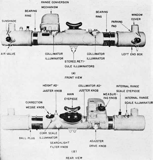
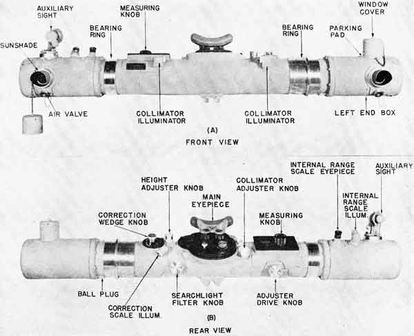
1. Rangefinder Mark 58, made by the Bausch and Lomb Optical Co., Rochester, N. Y., is of the erect image, stereoscopic wander mark type, 8 power, and fitted with a range conversion mechanism (see plate 1). For a description of the conversion mechanism for Rangefinders Mark 58. refer to Ordnance Data 3766.
PRINCIPLES.
2. Path of Light.-In this instrument the light rays forming the target images enter at two wedge windows 1.5 meters apart (see plate 2). The rays entering the left wedge window are deviated 90° by the left penta prism, then pass through the various optical elements of the left system, are deviated by the left ocular prism, pass through the various elements of the left eyepiece system, and finally enter the left eye of the rangetaker. The rays entering the right wedge window travel a similar path.
3.Measuring Marks.-If the instrument is directed toward a target the rangetaker sees in each eye an image of the reticule marks (see plate 2) and an image of the target. If the compensator wedges are rotated by means of the measuring knob (see plate 1) a relative movement, in depth, will be observed between the stereoscopic images of the reticule marks and the target image. Stereoscopic contact with the measuring mark (center diamond) is established when the fused target and the measuring mark images appear to lie in the same plane. The range of the target is then read on a scale which is calibrated to give the range in yards.
4. The general principle of stereoscopic vision and stereoscopic rangefinders is thoroughly
explained in Ordnance Pamphlet 105, "Optical equipment, Rangefinders, Care and Operation" and O.P. 556, "Principle of Stereoscopic Vision", which supplement this pamphlet. Anyone involved with the care and operation of stereoscopic rangefinders should be thoroughly familiar with these two pamphlets.
OPTICAL CHARACTERISTICS.
5. The optical characteristics of this instrument are as follows:
Base Length
1.5 meters
Magnification
8X
True Field
6°
Exit Pupil (center)
3.0 mm.
Exit Pupil (edge)
1.5 mm.
Eye distance
21.0 mm.
Light Transmission
Approx. 15%
OPTICAL SYSTEMS.
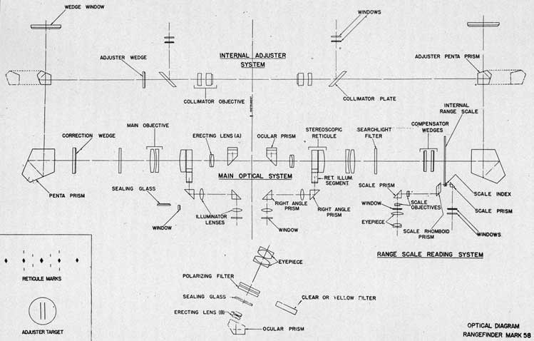
6. Plate 2 is a diagram of the optical systems of Rangefinder, Mark 58. The optical parts may be grouped into three different systems as follows:
(1) Main optical system.
(2) Range scale reading system.
(3) Internal adjuster system.
MAIN OPTICAL SYSTEM (GENERAL).
7. The main optical system (Plate 2) consists of wedge windows, penta prisms, correction and compensator wedges, searchlight filters, main objectives, stereoscopic reticules, erecting lenses, ocular prisms, sealing glasses, rayfilters and eyepieces.
8. Light from a distant target enters the right wedge window, is deviated by the penta prism, passes through the compensator, searchlight filter (if used), and the main objective
6
which forms an image of the distant target in the plane of the stereoscopic reticule marks. The erecting lenses, in front of and behind the ocular prism, form an image of the target and the stereoscopic reticule in the focal plane of the eyepiece. The eyepiece forms an enlarged virtual image of the target and the reticule.
9. The light entering left wedge window travels a similar path except that the left system contains a correction wedge instead of a compensator.
MAIN OPTICAL SYSTEM (DETAIL).
10. Wedge Windows (Plate 2).-The wedge
PLATE 1.-Rangefinder Mark 58
7
PLATE 2
8
windows, frequently called end windows, are slightly wedge shaped and therefore deviate the incident rays through a small angle. By rotating the end windows the deviation in the plane of triangulation may be varied to correct errors in range which are caused by slight inaccuracies in the alignment or construction of certain optical parts. This adjustment is made at the factory on very accurately known ranges and under no circumstances should the windows be rotated except by qualified repair personnel.
11. Penta Prisms (Plate 2).-Each penta prism consists of a single piece of glass, ground and polished to the shape shown in plate 2. The two reflecting surfaces are silvered. The included angle between the reflecting surfaces of the left penta prism is 45° while the corresponding angle on the right pent prism is 45°3'9.6". The effect of these angles is to produce a 90° in the left penta prism and an 89°53'40.7" in the right penta prism. These deviations are constant in the plane of triangulation for all rays incident upon the penta prisms.
12. It can be shown that when a ray of light is incident on such a penta prism, the angle between the incident ray and the emergent ray is dependent on the angle between the reflecting surfaces. Therefore if the penta prisms are rotated on a vertical axis, no change in the direction of the emergent rays takes place and no deviation is introduced into the system. Since right angle prisms do not possess this property they cannot be substituted for penta prisms.
13. Correction Wedge (Plate 2).-The correction wedge is a weak wedge and its purpose in the system is to compensate for the deviations which are introduced into the system by thermal or mechanical stresses. These deviations are compensated for by rotating the correction wedge in a plane perpendicular to the longitudinal axis of the instrument. Rotation of the wedge introduces a variable deviation in the plane of triangulation. To an observer looking into the main eyepiece, the rotation of the correction wedge causes a relative movement, in depth, between the images of the adjuster target (or the external target) and the stereoscopic reticule marks.
14. Compensator Wedges (Plate 2).-(For additional information on the compensator refer to Ordnance Pamphlet No. 105). The compensator consists of two wedges of optical glass placed in the path of the light coming from the right penta prism toward the right objective. These wedges are equal in deviation and are mounted so that they may be rotated at equal rates in opposite directions.
15. The action of the wedges may be understood by referring to plate 4 O.P. 105 which illustrates the wedge positions as seen when looking down on the plane of triangulation of the instrument. In one extreme position the thick edges of both wedges will be together at one side, producing a total deviation which is twice that caused by one of them (see fig. 1, pi. 4, O.P. 105). If now they are rotated through 180° in opposite directions, the thick edges will again be together, producing the same total deviation but in the opposite direction (see fig. 3, pl. 4, O.P. 105). At the midposition, when the thick edges of the wedges are opposed, the deviation of one wedge is neutralized by that of the other and the resultant deviation is zero (see fig. 2, pl. 4, O.P. 105).
16. The deviation of each compensator wedge may be resolved into a component which is parallel to the plane of triangulation and another which is perpendicular. The wedges are placed in the rangefinder in such a manner that the parallel components reinforce each other while the perpendicular components cancel each other. In other words, rotating the compensator wedges at equal rates in opposite directions introduces a variable deviation on the plane of triangulation and no deviation in the plane which is perpendicular.
17. The rotation of the compensator wedges is converted into range by means of a transparent glass scale (internal range scale) attached to one of the wedges.
18. In order that the compensator wedges may be used in both directions from the midpoint position thus lengthening the range scale and reducing the deviation of the individual wedges, the right penta prism is designed to introduce a constant deviation of 89°53'40.7" which amounts to an initial deviation of 0°6'
9
19.3". This initial deviation is equal to the parallactic angle of a target at the "mean range".
19. When stereoscopic contact is established for instruments in which the penta prism introduces an initial deviation, the deviation of the compensator will be numerically equal to the difference between the parallactic angle of the target and the initial deviation of the right penta prism. At the infinity position of the compensator wedges the deviation of the compensator is numerically equal to the initial deviation; at the minimum range position the compensator deviation is numerically equal to the difference between the parallactic angle subtended by the minimum range and the initial deviation; and at the mean range position the compensator deviation is zero (see fig. 3, pl. 3, O.P. 105).
20. Searchlight Filters (Plate 2).-The searchlight filters are made of dark glass, substantially neutral in color and having a transmission of approximately 0.02 percent. They are used to reduce the intensity of the light when ranging on a bright searchlight. The left searchlight filter is mounted between the correction wedge and the left main objective and the right searchlight filter between the compensator and the right main objective.
21. The filters are not permanently located in the path of the rays but may be inserted into the optical system, simultaneously by rotating a searchlight filter knob.
22. Main Objectives (Plate 2).-The main objectives are achromatic doublets, the elements of which are separated by an air space. The thickness of the air space for the right objective may be increased or decreased so that the focal lengths of the objectives may be equalized. The function of the objectives is to form an image of a distinct target in the plane of the stereoscopic reticule marks.
23. Stereoscopic Reticules (Plate 2).-Each stereoscopic reticule consists of a scale disc which is Cemented between a cover glass and a collective lens. On each scale disc is engraved or deposited a pattern similar to the one shown in the lower corner of plate 2.
24. If these patterns are viewed
stereoscopically through the eyepieces of the instrument, the reticule marks appear to lie a various distances from the observer. The five diamonds on the horizontal diameter of the field appear to lie at the same range. The angular separation between adjacent marks is 10 mils. Approximately above and below the second and fourth diamonds (counting from either end) is another mark so located that a line connecting its center with the center of the measuring mark, makes an angle of 13° with the horizontal diameter of the field. The stereoscopic range of each of the two marks in the lower half of the field exceeds that of the measuring mark by 100 units of error and each of the two marks in the upper half of the field are less than that of the measuring mark by 100 units of error. Midway between each of these marks and the measuring mark, on the 13° lines, is located another mark which is midway in stereoscopic range between the measuring mark and the adjacent mark on the 13° line.
25. Stereoscopic Reticule Illuminator System (Plate 2).-Illumination for both stereoscopic reticules is provided for night use. Each illuminator system consists of a window, two right angle prisms, and two illuminator lenses. The lenses form an image of the lamp filament in front of the reticule illuminating segment and the light enters the segment and the stereoscopic reticule. The edges of the reticule are polished and silvered so that the incident light undergoes multiple internal reflections. This reflected light is intercepted by the reticule marks and to an observer looking into the eyepiece at night, the reticule marks appear luminous against a dark background.
26. Erecting Lenses "A" and "B" (Plate 2).-The main objectives form inverted images of the target on the stereoscopic reticules. These images are again inverted and also projected into the focal plane of the eyepiece by erecting lenses "A" and "B". The final image of the target will therefore appear erect to an observer looking into the main eyepiece.
27. Erecting lens "A" is placed in front of the ocular prism and erecting lens "B" is placed behind the ocular prism.
28. Ocular Prisms (Plate 2).-The light from erecting lens "A" enters the ocular prism and
10
is twice reflected by two silvered surfaces before emerging from the prism. The first deviates the light 90° toward the target side of the instrument and the second deviates the light upward at an angle which makes approximately 115° with the line of sight.
29. Rayfilters (Plate 2).-Two rayfilters, yellow and variable density, and a colorless glass are provided for both the right and left rangefinder systems. In general the yellow filter is used for increasing contrast when ranging in haze or mist and for reducing the apparent effect of heat waves.
30. Each variable density filter consists of two polarizing plates, one fixed and the other rotatable on an axis perpendicular to the surface of the plate. Rotation of the plate through 90° varies the intensity of the transmitted light from a maximum to a minimum. The variable density filter is used when ranging into extreme sunglare, searchlights, or brilliant sunshine.
31. Eyepieces (Plate 2).-Each eyepiece consists of a doublet field and a doublet eye lens mounted in a suitable cell behind the rayfilters. These eyepieces are separately adjustable for focusing from plus 2 to minus 4 diopters.
RANGE SCALE READING SYSTEM
(Plate 2).
32. The internal range scale is a thin transparent glass ring which is attached to, and rotates with one of the compensator wedges. The scale is graduated from 750 to 10,000 yards and at infinity. The 5000 yard graduation is marked with an asterisk to indicate the range at which the scale must be set when making an internal adjustment.
33. An observer looking into the range scale eyepiece views an illuminated, erect, and magnified image of a portion of the range scale and the range scale index. The illumination is provided by means of a lamp mounted in a housing attached to the exterior of the outer body tube. The light passes through two windows, a right angle prism, the range scale index, and a portion of the range scale. The light continues through the rhomboid prism, the first scale objective, a right angle prism, the second scale objective, and a window. The scale objectives form an
image of the range scale and the index in the focal plane of the range scale eyepiece.
INTERNAL ADJUSTER SYSTEM (Plate 2).
34. Errors in the rangefinder must be detected and corrected before accurate ranges can be determined. This may be done by using a target at an accurately known range. Since targets at known ranges are not always available in service, rangefinders are equipped with an optical system which provides such a target. These optical systems are called internal adjusters.
35. The optical construction of the internal adjuster is shown in plate 2. It consists of two collimator objectives, two collimator plates, two adjuster penta prisms, and one adjuster wedge.
36. Collimator Objectives (Plate 2).-Each collimator objective consists of two lenses and a plane parallel plate which is cemented to the plano-convex lens of the objective. On the cemented surface of the plane parallel plate are engraved two parallel lines (later models have a single line) which when the instrument is properly adjusted, lie in the focal plane of the opposite collimator objective. The engraved parallel plates are sometimes referred to as collimator reticules or adjuster targets (see plate 2).
37. Collimator Plates (Plate 2).-The plane parallel collimator plates reflect the light from 6 volt Mazda lamps mounted in sockets which are enclosed in lamp wells secured to the exterior of the outer body tube. The reflected light illuminates the engravings on the collimator reticules.
38. Adjuster Wedge (Plate 2).-The adjuster wedge is inserted in the system to compensate for deviation errors in the internal adjuster system which result in the correction scale reading being too far removed from the midpoint when making an internal adjustment. By rotating the adjuster wedge this condition may be corrected. This adjustment is made at the factory and under no circumstances should the adjuster wedge be rotated except by experienced repair personnel.
39. Adjuster Penta Prisms (Plate 2).-Each adjuster penta prism, frequently called adjuster prism, consists of a piece of glass ground and
11
polished to the shape shown in plate 2. The two surfaces at which the reflections take place are silvered. The optical principles involved are the same as those discussed under penta prisms in paragraph 11.
40. The adjuster penta prisms are mechanically arranged so that they may be moved in or out of the optical path.
41. Path of Light (Plate 2).-Light proceeding from the engraving on the left objective is collimated by the right objective, passes through the collimator plate, and is reflected into the main system by the right adjuster penta prism. Similarly, the light from the engraving on the right objective is collimated by the left objective, passes through the collimator plate, the adjuster wedge, and is then reflected into the main system by the left adjuster penta prism. To an observer looking into the eyepieces of the instrument, the collimator lines may or may not appear in stereoscopic contact with the measuring mark when the internal range scale is set on 5,000 yards. If not, then a deviation error is indicated and the correction wedge must be rotated until contact is established.
STRUCTURE (GENERAL).
42. The various parts of the rangefinder are mounted in or on three tubes: the outer body tube, the inner body tube, and the optical tube. The inner and outer body tubes are concentric and the optical tube is mounted slightly off the body tube centerline.
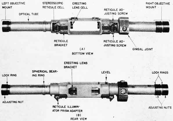
43. The outer body tube is a seamless steel tube to which are attached the various external fittings of the instrument. Both ends are closed with end boxes which may be removed for cleaning or adjusting the penta prisms and adjuster penta prisms. The tube is made pressure tight by fitting covers, and gaskets to the various openings and fitting packing glands to all shafts which pass through the outer tube. To retard the detrimental effects of sudden variations in temperature, the outer surface of the tube and the end boxes are covered with a layer of felt and a layer of canvas. During transportation, storage, or use the instrument is supported at the bronze bearing rings (see plate 1A) which are firmly secured to the tube.
44. The inner body tube is also a seamless steel tube and it carries most of the optical elements in the rangefinder. The penta prisms, adjuster penta prism, compensator and correction wedges. are mounted at the ends of the tube; the optical tube, and collimator at the center. Since various parts in the inner body tube must be kept in practically perfect alignment, the inner tube supports are designed in such a manner that no distortion of the outer body tube can be transmitted to the inner body tube.
45. The optical tube is a nickel plated steel tube machined out of a single forging. It carries the main objectives, stereoscopic reticules, "A" erecting lenses, and two right angle prisms for the reticule illuminating system. Variations in the relative position of the objectives and the stereoscopic reticules may introduce serious errors in range. The optical tube is ' therefore supported in such a manner that it will not be affected by any distortion of the inner body tube.
STRUCTURE (DETAIL).
46. Inner Body Tube Supports.-Each end of the inner body tube is supported in the outer by means of two bronze bearing rings (see plate 3). One bearing ring is secured to the outer diameter of the inner body tube and the other to the inner diameter of the outer body tube. The contacting surfaces on the inner body tube ring are spherical while those on the outer body tube are cylindrical.
47. A ball plug (see plate 1B) is firmly secured to the outer body tube and closely fitted to reamed holes through the body tubes and the left bearing rings. The plug limits rotational and axial movements of the inner body tube with respect to the outer.
48. Optical Tube Assembly.-The optical tube is tubular in cross-section with the exception of a hollow rectangular boxed section in the center, which carries the "A" erecting lenses (see plate 6). The stereoscopic reticules are mounted in the optical tube in front of the "A" erecting lenses and two right angle prisms for the reticule illumination are attached to the tube immediately under the stereoscopic reticules. The tube is supported on the right by
means of a gimbal joint and on the left by a height adjuster mechanism. The objectives are mounted in cells at the ends of the tube.
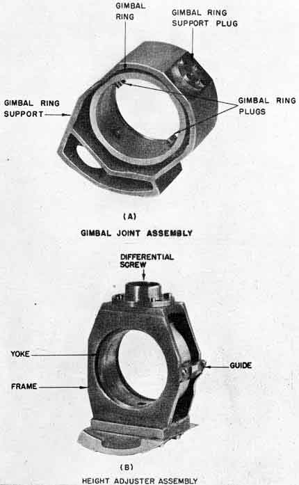
49. Gimbal Joint Assembly.-The gimbal
joint assembly is shown attached to the optical tube in plates 5A and 6 and separately in plate 4A. Two plugs are fitted to reamed holes in the optical tube and fastened to the steel gimbal
PLATE 4.-Optical Tube Supports-Rangefinder Mark 58
ring. 90° from these plugs are two additional plugs which are fitted to reamed holes in the gimbal ring and fastened to the bronze gimbal ring support. This arrangement holds the optical tube in position rotationally and longitudinally but still allows it to pivot at the gimbal joint in any direction.
50. Height Adjuster Assembly.-The height adjuster mechanism is shown in plates 4B and 5B. The yoke which is fitted to a spherical ring turned on the left end of the optical tube is adjustable in a vertical plane. The yoke is supported in the frame by means of a spring at the bottom and a differential screw at the top. The screw is connected to the height adjuster knob by means of a ball rod. Rotation of the knob causes the yoke and the left end of the optical tube to move vertically. Adjustable set screws in the support limit the number of knob
rotations and therefore the vertical movement of the optical tube.
51. Main Objective Cells.-Each element of the right main objective is mounted in a separate cell which is designed so that the objective may be moved as a whole for focusing, or one element may be moved relative to the other for equalizing the focal lengths of the main objectives. The elements of the left main objective are mounted in a single cell and can therefore be moved only as a whole.
52. A section through the right objective mount is shown in plate 7. If the right inner adjusting nut (see plate 6B) is turned the objective moves as a whole; if the right outer adjusting nut is turned only the convex lens moves. The adjusting nut on the left end of the optical tube moves the objective as a whole. Holes in the inner and outer body tubes allow
PLATE 6.-Optical Tube Assembly-Rangefinder Mark 58
these adjustments to be made after the instrument has been completely assembled.
53. Stereoscopic Reticule Cells.-The stereoscopic reticules are mounted in cells which are secured to the optical tube by means of right angle brackets. The reticules may be rotated through a small angle to correct tilt by means of adjusting screws (see plate 6A) which contact the lower part of the reticule cell.
54. The mountings for the reticule illuminating system are shown in plate 7. The lamp housings are attached to the outer body tube directly under the main eyepiece assembly. The first illuminating lens seals the opening in the instrument. The right angle prism is mounted on a bracket and the second illuminating lens, adjustable laterally for focusing, is attached to the inner body tube. The second right angle prism is attached to the optical tube, and the illuminating segment is mounted in the reticule cell.
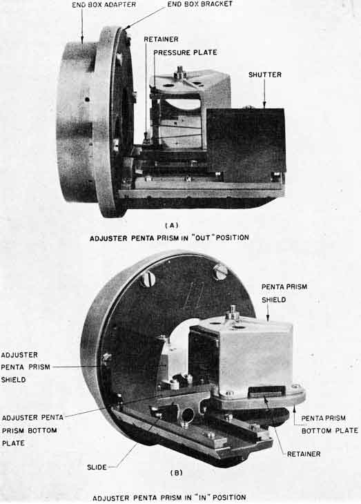
55. End Box Assembly.-A section through the end box is shown in plate 3. The adjuster penta prism and the penta prism are enclosed by the outer body tube of the instrument and the end box tube. The ends of both tubes are closed by brass caps. The penta prism assemblies are rigidly secured to the inner body tube by means of an end box adapter and bracket (see plate 8).
56. Penta Prism Mounts.-The penta prism is secured to the penta prism bottom plate by means of retainers which contact the sides of the prism and a screw through the top of the penta prism shield which exerts a very slight pressure on the pressure plate. Three large screws secure the bottom plate to the end box bracket.
57. Adjuster Penta Prism Mounts.-The adjuster penta prism and the penta prism are mounted in exactly the same manner except that the former is mounted on a slide which may be moved longitudinally, in or out of the path of light coming through the end window. A shutter attached to the slide closes the end window when the adjuster prism is placed in front of the penta prism. Plate 8 shows the adjuster prism in the "IN" and "OUT" positions.
58. Wedge Window Cells.-Each wedge window is mounted in a cell which is placed in an adapter soldered to the exterior of the end box outer tube (see plate 3). The cells are held in position by means of a clamp ring on which arbitrary graduations have been placed. By loosening the clamp ring the window cell may be rotated for range correction. An index on the window cell opposite the graduations on the clamp ring indicates the amount the wedge window has been rotated. This adjustment is made at the factory and should not be disturbed except by qualified repair personnel.
59. When the instrument is not in use the windows are closed by means of the window covers shown in position on the parking pads in plate 1A.
60. Adjuster Tubes.-The adjuster tubes which extend from the ends of the collimator to the end boxes are thin walled copper tubes internally blackened throughout their length. The inner ends of the tubes are fastened to the inner body tube and the outer ends are held by the end box adapter.
61. These tubes serve three purposes in the instrument: (1) they minimize the interference which may be caused by air currents in the instrument, (2) they reduce internal reflections, and (3) they prevent the obstruction of the light paths by various parts in the rangefinder.
62. Air Valves.-One air valve is secured to each end box immediately under the end windows (see plate 1A). These valves are used to desiccate the instrument. Gas entering one valve circulates through the instrument and escapes through the other. In this manner all internal parts of the instrument can be dried by a current of dry gas.
63. Adjusting Drive Assembly.-The adjusting drive mechanism is used to throw the adjuster penta prisms in and out of the main system before or after making an internal adjustment. This is done by rotating the adjuster drive knob which is located on the exterior of the outer body tube to the right of the range taker (see plate 1B). The rotation of the knob is transmitted by means of a self-aligning shaft to a spur gear pinion which
18
PLATE 8.-End Box Bracket Assembly-Rangefinder Mark 58
engages two racks: one at the top of the pinion and the other at the bottom (see plate 9). These adjuster drive racks are connected by means of a tube to the adjuster penta prism slides. Rotation of the adjuster drive knob causes the adjuster drive racks to move in opposite directions and the adjuster prisms to move into or out of the main system. The prisms are held in either position by means of a detent in the knob.
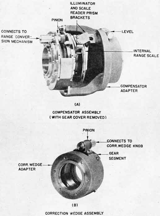
64. Compensator Assembly.-The compensator is secured to the right end box adapter by means of the compensator adapter (see plate 10A).
65. Each compensator wedge is mounted in a cell which is fitted to a flanged tubular housing that rotates on ball bearings (see plate 11). Spur gear teeth are cut in the flanges. A wide face pinion mounted on a taper shaft engages the spur gear on the housing which carries the internal range scale. A ball socket on the end of the taper shaft connects this pinion with the range conversion mechanism. A second, pinion of the same size engages the first pinion and also engages the other spur gear. Rotation of the first pinion rotates the spur gear carrying the internal range scale and also the second pinion which in turn rotates the other spur gear. If the wedge connected to the internal range scale rotates clockwise then the other wedge rotates counterclockwise at the same rate.
66. The brackets carrying the scale reader prisms and the index are attached to the side of the compensator.
67. Correction Wedge Assembly.-The correction wedge is secured to the left end box adapted by means of the correction wedge adapter (see plate 10B).
68. The wedge is mounted in a cell and screwed into a flanged tubular housing which may be rotated on the longitudinal axis of the instrument. Spur gear teeth cut in a segment of the flange are engaged by a pinion. A ball socket on the end of the pinion shaft connects the correction wedge to the correction wedge knob which is located to the left of the range taker (see plate
18). Rotation of the knob is transmitted to the pinion through a pair of bevel gears and a self-aligning shaft (see plate 12). The amount of rotation is limited by means of a screw in the correction wedge bearing and a pin in the correction wedge scale.
69. The correction wedge scale is attached to the knob shaft and is divided into 120 divisions which are contained in an arc of approximately 350°. Each interval is equivalent to one unit of error. Every fifth graduation is numbered: zero at one end of the scale and 120 at the other.
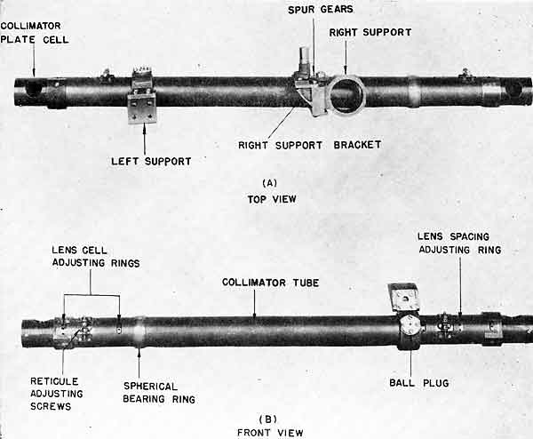
70. Collimator Assembly.-The collimator tube is a steel tube which carries the collimator objectives and the collimator plates. It is secured in the inner body tube immediately in front of the optical tube by means of two supports (see plate 13). The adjuster wedge is separately mounted at the left end of the collimator (see plate 14).
71. Collimator Objective Cells.-The collimator objective cells and the 'main objective cells in the optical tube are similar in principle: that is, the objectives may be moved as a whole for focusing and the elements of one objective may be moved relative to the other for equalizing the focal lengths. The objectives may be moved as a whole by loosening one lens cell adjusting ring (see plate 13B) and tightening the other. The elements of the left objective may be moved relatively by loosening one lens cell adjusting ring and turning the lens spacing adjusting ring.
72. The collimator objective cells are provided with reticule adjusting screws by means of which the reticule cells may be rotated to adjust the parallelism between the images of the collimator lines and the measuring marks.
73. Holes in the inner and outer body tubes allow these adjustments to be made after the instrument has been completely assembled.
74. Collimator Plate Cells.-The collimator plate cells are mounted on the ends of the collimator tube and hold the plates in such manner that the light from the collimator illuminators (see plate 1A) is reflected into the collimator tube.
75. Collimator Supports.-The collimator is secured to the inner body tube by means of the right and left supports which are fitted to two spherical rings turned on the outside
21
diameter of the collimator tube (see plate 13). Longitudinal and axial movement of the collimator
in the supports is prevented by means of a ball
plug attached to the left support and fitted to a reamed hole in the collimator tube and spherical ring.
76. Collimator Adjuster Knob.-When making an internal adjustment the measuring mark should be centered in the space between the collimator lines, or in the case of a single line, the space between the line and the measuring mark should be small. This adjustment is accomplished by means of the collimator adjuster knob located to the right of the range taker (see plate 1B). The rotation of the knob is transmitted by means of a self-aligning shaft to two spur gears, one of which is attached to the right support bracket and the other to a screw which engages a threaded hole in the support (see plate 13A). The support is fitted to a slide in the support bracket. Rotation of the knob causes the support and the right end
of the collimator to move toward the front or rear of the instrument with the left support acting as a fulcrum. Through the eyepieces the collimator lines appear to move to the right or left.
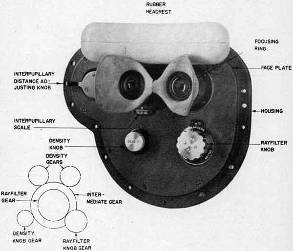
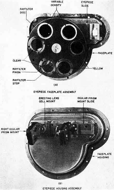
77. Main Eyepiece Assembly.-The main eyepiece assembly is mounted on the outer body tube midway between the ends of the instrument and inclined so that the optical axes of the eyepieces make an angle of 115° with the line of sight to the target (see plate 1B). The assembly may be divided into two subassemblies: the eyepiece face plate assembly (see plate 16A) and the eyepiece housing assembly (see plate 16B) . The faceplate carries the ray-filters and the eyepieces; the housing carries
the ocular prisms and the "B" erecting lenses. The eyepiece, erecting lens, and the ocular prism for the right system is fixed while the same parts for the left system may be moved laterally through a distance of approximately 15 millimeters.
78. Four adjustments must be made on the main eyepiece assembly by the range taker before beginning to range on a target. These are: headrest, eyepiece focus, interpupillary distance, and rayfilters.
79. Headrest.-The headrest may be raised or lowered by means of the knurled knobs immediately under the rubber headrest (see plate 15).
80. Eyepiece Focus.-The eyepieces may be separately focused from plus two to minus four diopters by turning the focusing rings (see plate 15). By means of straight and spiral keys the rotation of the focusing ring is converted to an in and out movement (without rotation) of the lens cell. The focusing ring carries a diopter scale which moves against a stationary index.
81. Interpupillary distance.-By means of the interpupillary distance adjusting knob (see plate 15) the distance between the optical axes of the eyepieces may be altered to suit the interpupillary distance of the observer. The mechanical arrangement for accomplishing this
PLATE 15.-Main Eyepiece Assembly-Rangefinder Mark 58
27
PLATE 16.-Main Eyepiece Assembly-Rangefinder Mark 58
28
is as follows: The left eyepiece is attached to the eyepiece slide which is mounted on the underside of the faceplate (see plate 16A) and the left "B" erecting lens and ocular prism are attached to the ocular prism mount slide on the underside of the housing (see plate 16B). The position of these slides is determined by the position of the interpupillary distance adjusting knob. Rotation of the knob causes both slides to move laterally in the same direction at the same rate. This is accomplished by means of an eccentric axis which engages sliding shoes in the eyepiece and ocular prism mount slides (see plate 17).
82. An index attached to the left eyepiece slide moves opposite a scale on the eyepiece faceplate and indicates the interpupillary distance in millimeters.
83. Rayfilters.-Four rayfilters, two yellow, two variable density, and two colorless glass plates are mounted on a disc which rotates on an axis secured to the underside of the faceplate (see plate 16A). The rotation of the knob is transmitted to the rayfilter disc by means of a rayfilter pinion and a rayfilter gear. The pinion is pinned to the knob and the gear is secured to the disc. The rayfilters are held in position by means of a spring plunger which drops into V-grooves in a flanged disc attached to the rayfilter knob shaft.
84. If the polarizing plates are placed in the system the intensity of the light emerging from the instrument may be varied by rotating the density knob on the eyepiece faceplate. The mechanical arrangement for accomplishing this is as follows: The cells for the upper and lower polarizing plates of both the right and left systems are mounted on the rayfilter disc (see plate 17). The. lower cells are fixed and the upper cells may be rotated on an axis perpendicular to the plate surfaces. The density gears (see diagram on plate 15) attached to the upper place cells engage an intermediate gear which rotates on the rayfilter disc axis. The intermediate gear engages the density knob gear on the knob shaft. Therefore a rotation of the density knob causes both upper polarizing plates to rotate at the same rate and the change in intensity of the emergent light is equal for both the right and left systems.
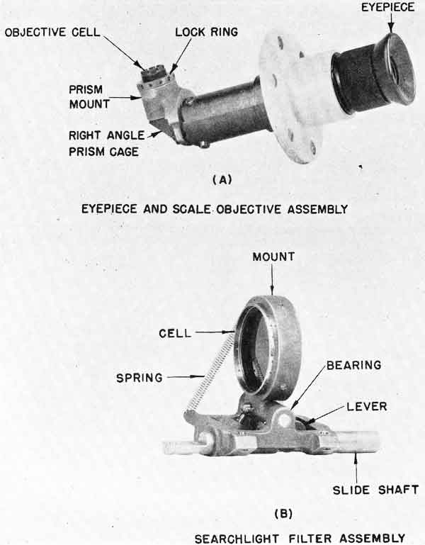
85. Internal Range Scale Reading System.-The internal range scale eyepiece and illuminator are mounted on the right end box (see plate 1B). To the eyepiece are attached both scale objectives and a right angle prism (see plates 18A and 11). The objectives are mounted in cells which are externally threaded and screwed into the prism mount. Lock rings hold the objectives in position. The objectives are focused by loosening the lock rings and rotating the cells.
86. Searchlight Filter Assembly.-The searchlight filters are mounted on bearings (see plate 18B) which are secured to the inside diameter of the inner body tube in front of the main objectives. The mounting is such that the filters can be tilted on an axis either in or out of the main optical system. Rotation of the searchlight filter knob (see plate 1B) transmits a longitudinal movement to the connecting rods inside the inner tube (see plate 19). These rods are connected to the searchlight filter slide shafts and actuate levers which cause the filters to be tilted in or out of the optical path. A spring attached to the mount and to the bearing holds the filter at either the "IN" or "OUT" position.
ADJUSTMENTS.
87. Height Adjustment.-Differences in target height with respect to the measuring marks must be corrected before ranging. The height adjustment is made:
(1) by placing the bottom tip of the measuring mark in the right field of view close to but not touching some horizontal line such as the horizon, and
(2) rotating the height adjuster knob until the image of the same line in the left field of view is close to but not touching the bottom tip of the measuring mark. This method assumes a stationary condition, however, satisfactory height adjustments can be made with a slight motion.
88. Height adjustments should be checked frequently but readjustment should not be necessary except when it has been tampered with or extreme changes of temperature have taken place.
adjustment is made by turning the interpupillary distance adjusting knob until the desired distance is indicated on the scale.
90. Focus Adjustment-Focus adjustment is made by rotating the eyepiece focusing rings, from plus to minus only, until the reticule marks appear sharp. The operator is cautioned against an excessively negative diopter setting.
91. Interpupillary and focus adjustment should be made by scale, the settings having
been determined by previous measurement of the operator's eyes.
92. Internal Adjustment.-Internal adjustment is made by first throwing the lighting switches to illuminate the correction scale, the adjuster targets, and the internal range scale. The adjuster drive knob is then rotated counterclockwise until it reaches its stop. This throws in the adjuster penta prisms and places the shutters over the end windows. The internal
range scale is set at 5,000 yards and the covers are removed from the correction wedge and collimator adjusting knobs. The measuring mark is centered in the space between the two vertical collimator lines by turning the collimator adjusting knob. In the case of a single collimator line, the line is placed close to, but not touching the measuring mark. If the correction wedge knob is rotated, a relative movement, in depth, between the measuring mark and the adjuster targets will be observed. When they appear to lie in the same depth plane the adjustment is satisfactory and the correction scale is read.
93. To determine the correct value of the internal adjustment before ranging with the instrument, at least five correction scale readings should be taken and the readings averaged. The correction scale should then be set to this average reading plus or minus the operator's index correction. The internal range scale should be checked to insure that it has remained on 5000 yards. Knob covers are replaced and the adjuster knob rotated clockwise until it reaches its stop. The lighting switch is then turned for the lighting desired and the instrument is ready for ranging.
94. Rayfilters.-Yellow, variable density, and colorless glass plates are provided. These may be inserted into the system by turning the ray-filter knob on the eyepiece faceplate. An engraved scale attached to the knob moves past an index which indicates the position in which the knob must be placed to introduce a given filter into the system.
95. If the polarizers are placed in the system the intensity of the light emerging from the instrument may be varied by rotating the density knob on the eyepiece faceplate.
96. Searchlight Filter.-The searchlight filters are placed in the system by rotating the searchlight filter knob. Rotation of the knob in one direction places the filters in the system; rotation in the opposite direction removes them.
97. Assembly Adjustment.-During the manufacture of the rangefinder, several fixed adjustments are made which, for general information, will be briefly described but which should be attempted only by repair ship personnel if such readjustment is considered necessary.
Means for these adjustments are provided as follows:
(a) To correct for the constant error in the measurement of the parallactic angle by the rangefinder, the end windows are made slightly wedge-shaped. On these rangefinders the maximum deviation which one end window can produce is plus or minus 40 seconds of arc which is equivalent to plus or minus 26.66 units of error. Thus the total range of adjustment by means of the two end windows is plus or minus 53.32 units of error. Only a small amount of this adjustment is necessary and this is usually introduced by turning the right end window only.
(b) The position of both main objectives and the focal length of the right main objective are adjustable. The objectives may be moved as a whole in order to bring the focal planes of the objectives into coincidence with the plane of stereoscopic reticule marks. The air space between the elements of the right objective may be varied to equalize the focal lengths of the main objectives.
(c) The different assemblies can be adjusted as units before installation within the rangefinder but where these assemblies are related to each other after installation, means have been provided for adjusting any difference between them.
(d) If the difference between the transmitted range and the range indicated by the internal range scale is consistently high or consistently low at various ranges, then the compensator and the range transmission mechanism may be out of step. This condition may be corrected by means of the tangent screws on the compensator drive ball rod shown in plate 11.
(e) The collimator (adjuster target system) must be provided with the same optical adjustments as the main optical system. Hence means are provided for varying the position of both objectives and the focal length of one of them. The adjuster wedge permits an adjustment of the collimator system similar to the end window adjustment of the main optical system.
ACCURACY.
98. Unit of Error.-The term "unit of error", whenever used in connection with these
33
instruments, is defined as that error, at any given range, which is equivalent to an error of 12 seconds of arc, divided by the magnification, in the measurement of the angle subtended by the base length of the rangefinder. For convenience the following table of errors in yards corresponding to one "unit of error" for various ranges is given:
Range
Error
Range
Error
Range
Error
750
2.5
4000
70.9
7500
245.0
1000
4.4
4500
89.8
8000
283.8
1500
9.9
5000
110.9
8500
320.0
2000
17.7
5500
134.1
9000
359.2
2500
27.7
6000
159.6
9500
400.3
3000
39.9
6500
187.3
10000
443.5
3500
54.3
7000
217.3
CARE OF THE RANGEFINDER.
99. The provisions of Chapter II, Ordnance Pamphlet No. 105, on the care and handling of rangefinders should be observed.
100. Gas Filling.-Rangefinders are sealed pressure tight to confine the gas with which they are charged and to prevent entrance of dirt, moisture, or other foreign matter. The pressure tightness of the instrument should not be disturbed except by those qualified to do so.
101. Lubricating and Cleaning.-The cleaning and lubricating of the various mechanisms in these instruments need not be done except at a time when a general overhaul is being made.
RANGEFINDER MARK 58 MOD. 1
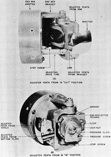
102. The principal difference between Rangefinders Mark 58 and Mark 58-1 is in the design of the end box bracket assembly. The sliding adjuster penta prism is replaced with one that swings in an arc and the penta prism in the main system is replaced by an end reflector (compare plates 8 and 20). The external appearance of the two instruments is identical.
103. End Reflectors.-.Each end reflector consists of two front surface, aluminized, glass mirrors mounted on a steel housing with their reflecting surfaces facing each other (see plate 20). The included angle between the reflecting surfaces and also other properties of the end reflectors are the same as those discussed in paragraphs 11 and 12 for the penta prism.
104. Each end reflector mirror contacts the face of the housing at three narrow spots located 120° apart. The mirrors are centered on the faces by means of three cleats which contact the edges of the mirror and are attached to the housing faces near the three spots. The mirrors are held against the housing faces by a pressure plate under the action of an adjustable spring. The pressure plate contacts the mirror at three narrow spots directly over the three spots on the face of the housing. The spring pressure is applied at the center of the pressure plate.
105. Adjuster Penta Prism.-The adjuster penta prism is located on the adjuster penta prism bottomplate by means of retainers and held in position by means of a pressure plate and screw (see plate 20B). The pressure plate rests on the top of the adjuster prism and the screw that passes through the top of the shield exerts a very slight pressure on the pressure plate. The penta prism is secured to the adjuster penta prism bracket (see plate 20A) which is attached to the adjuster penta prism arm. The arm is mounted on the end box bracket by means of ball bearings and is free to rotate on a vertical axis.
106. The adjuster penta prism arm is connected to the; adjusting drive tube by means of a link. Rotation of the adjuster knob imparts a longitudinal motion to the drive tube causing the adjuster penta prism to swing in a horizontal plane into or out of the path of the rays from the collimator. A shutter attached to the adjuster penta prism bracket closes the end window when the adjuster penta prism is placed in front of the end reflector. Plate 20 shows the adjuster penta prism in the "IN" and "OUT" positions.
107. Travel of the penta prism arm is limited by means of stop screws in the end box bracket and in the adjuster prism arm.
34
PLATE 20.-End Box Bracket Assembly-Rangefinders Mark 58-1 and Mark 65
35
RANGEFINDER MARK 65
108. The principal differences between Rangefinders Mark 58 and Mark 65 is the end box bracket assembly, the range conversion mechanism and the auxiliary sight. Front and rear views of the instrument are shown in plate 21.
109. End Box Bracket Assembly.-The end box bracket assembly for Rangefinder Mark 65 is the same as Mark 58-1 (see paragraphs 102 to 107 inclusive).
110. Measuring Knob Assembly.-The range conversion mechanism on Rangefinder Mark 58 is replaced by a measuring knob assembly on Rangefinder Mark 65. (Compare plates 1 and
21). The rotation of the measuring knob is transmitted to the compensator by means of a pair of bevel gears and a drive tube. The number of rotations is limited by means of stop rings in the knob.
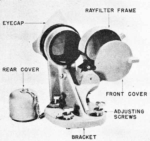
111. Auxiliary Sight.-The auxiliary sight which is used to train the instrument on the target is shown mounted on the instrument in plate 21 and separately in plate 22.
112. The auxiliary sight is secured to the right end box close to the range scale eyepiece by means of adjusting screws (see plate 22). The optical element of the sight is mounted in the bracket aid a red rayfilter and front cover
PLATE 21.-Rangefinders Mark 65 and Mark 65-1
36
are individually mounted on an axis attached to the bracket. Detents in the axis hold the filter and cover in either the "IN" or "OUT" position. A rear cover closes the eye end of the sight.
113. The line of sight is adjusted by means of the adjusting screws so that toe left line of sight of the instrument and the line of sight of the auxiliary sight converge at a distance of approximately 3000 yards.
RANGEFINDER MARK 65 MOD. 1
114. The principal difference between rangefinders Mark 65 and Mark 65-1 is in the design of the end box bracket assembly. Mark 65 is equipped with an end reflector and a swinging adjuster prism (see plate 20); Mark 65-1 with a penta prism and a sliding adjuster prism (see plate 8). The end box bracket assembly for. Mark 65-1 and Mark 58 are identical.
115. Front and rear views of Rangefinder Mark 65-1 are shown in plate 21.
SUMMARY OF PRINCIPAL DIFFERENCES
RANGEFINDERS MARK 58, 58-1 65, AND 65-1.
Rangefinders
58
58-1
65
65-1
Range conversion mechanism
Yes
Yes
No
No
Penta prism and sliding adjuster penta prism
Yes
No
No
Yes
End reflector and swinging adjuster penta prism
No
Yes
Yes
No
Measuring knob assembly
No
No
Yes
Yes
Auxiliary sight
No
No
Yes
Yes
PLATE 22.-Auxiliary Sight-Rangefinder Mark 65 and Mark 65-1
Requests for additional copies of OP 1171 (Preliminary) should be directed to the nearest BuOrd Publications Distribution Center: Navy Yard, Washington, D. C.; Mare Island, California; Adak, Alaska; Pearl Harbor, Hawaii; Espiritu Santo, New Hebrides; Exeter, England. Distribution Center mailing addresses should be obtained from list 10 nn on the Standard Navy Distribution List.
DISTRIBUTION:
Standard Navy Distribution List No. 22.
2 copies each unless otherwise noted.
1. (1 copy) , k, l; 1.a-c, r, ii, ll, ss, tt, zz; 2..b, k, r; 3.b*, e*, f*, ff*, h*, m, q*, dd*, ee*, ff, gg*, kk*, 11*, pp*, qq*, rr*; 4.b*, e*, f*, h*, m, q*, dd*, ee*, ff*, gg*, kk*, ll*, pp*, qq*, rr*; 5.b; 7.f-h; 7. (5 copies) , j, l(NRB San Diego and Ship Repair Units only); 7. (10 copies) , a; 8.h, n (SPECIAL LIST, I, J, K, L, O, T, GG), 11; 10. (25 copies) , nn; 12.a, b (Revision 1); 14.a, q.