Before a current can flow, a CLOSED and COMPLETE path
must be present for the electrons to follow. The path
must extend from the source of emf through elements in
the circuit and back to the source.
You have had some experience with circuits already,
and you know something of their characteristics. As an
example, when you flip a switch to turn on an electric
light, you closed a circuit. And when you throw the
switch in the opposite direction, you turn off the light
by breaking the circuit.
A string of lights on a Christmas tree is an example of
another type of circuit. If all the lights are good, and
none are turned out of their sockets, all will remain
lighted. But if one is burned out or loose in its socket,
all will be out.
699198°-46-3
25
You know too, that if a fuse in a circuit is burned out,
the electrical device, what ever it may be, will be dead.
And before the device can operate, the fuse must be replaced. Thus in any electrical circuit, a CLOSED AND
COMPLETE PATH from the source of emf through the electrical device and back to the source MUST BE PRESENT if
the device is to operate.
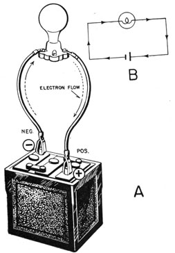
Look at figure 21. A COMPLETE PATH is present from
the negative terminal, through the lamp, and back to the
Figure 21.-A simple circuit.
positive pole of the battery. It is complete and without
breaks.
If one clamp is removed from the battery, a conductor
broken. or the lamp removed from the socket, the CIRCUIT
26
IS BROKEN, because a complete path is not present for the
electrons to follow.
SWITCHES are placed in circuits to provide a safe and
convenient way of making and breaking the paths.
When the switch is closed, the circuit is complete, but
when the switch is opened, the path is broken, and current
ceases to flow.
SIMPLE AND COMPLEX CIRCUITS
Few electrical circuits are as simple as the one indicated in figure 21. Most radios contain hundreds of
elements, but before the circuit will function, a CLOSED
and COMPLETE path through all the elements must be
present for the electrons to follow.
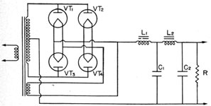
Figure 22.-A complex circuit.
Figure 22 is a complex circuit of the type you will find
in some radios. Right now it may not make sense, but it
does show the difference between the simple and complex
types.
If you wish to see a really complex circuit, get a schematic diagram of an RBA or RAL receiver.
SERIES AND PARALLEL CIRCUITS
In spite of the complex nature of any circuit, all are
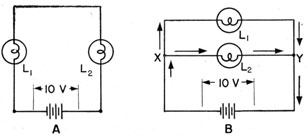
just combinations of two basic types, SERIES and PARALLEL. The lamps in figure 23A illustrate a SERIES circuit,
those in 23B a PARALLEL circuit.
27
In the series circuit, the current that flows through L1
also flows through L2. But in the paralleled circuit, the
current divides at point X, part flowing through L1 and
the rest L2. At point Y, the current combines and returns to the battery. Thus the current is the same at all
points of a series circuit, while in a parallel circuit it is
DIVIDED among the various branches.
If the resistances of the lamps in a parallel circuit are
EQUAL, the CURRENT THROUGH EACH LEG will also be
Figure 23.-Series and parallel circuits.
EQUAL. But if the resistance of ONE is LARGER than the
other, the current will be UNEQUAL, with the LARGER PORTION of the current flowing through the SMALLER resistance.
The VOLTAGE DISTRIBUTION is also different in series and
parallel circuits. In figure 23A, if 10 volts is applied to
the lamps, and the resistances of the lamps are equal,
half the voltage (5 volts) will appear across each. But
if the resistance of one lamp is greater than the other,
the LARGER portion of the voltage will appear across the
LARGER RESISTANCE.
Actually the voltage distribution across the lamps is
PROPORTIONAL to their resistances. As an example, if
the resistance are 200 ohms in L1 and 100 ohms in L2,
two-thirds of the applied voltage will appear across L1
and one-third across L2.
In PARALLEL CIRCUITS the voltage across ALL elements
is EQUAL. In figure 23B, for example, the voltage across
28
L1 and L2 will be equal, even if the resistance of one is
100 times the other.
RESISTANCES IN SERIES
Resistances connected in series are just like a sequence
of ladders connecting the lower decks with those topside.
If you wish to go from the fourth deck to the first, it will
be necessary for you to climb each ladder from 4th to
3rd, 3rd to 2nd, and 2nd to 1st.
The ladders are obstacles, or resistances, to be overcome-one after the other in series. Thus by the time
you reach the first deck, the total opposition to your
climb would be equal to the sum of all the individual obstacles.
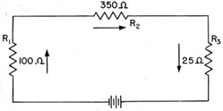
Figure 24.-Resistances in series.
In a series circuit you have the same story. The current flowing through the circuit in figure 24 must move
through each resistor in series. Therefore the total
opposition (resistance) to the flow of current is equal to
the sum of all the INDIVIDUAL resistances, or-
RT = R1 + R2 + R3 = 100 + 350 + 25 = 475 ohms
RESISTANCES IN PARALLEL
Resistances in parallel are like the SEVERAL ladders connecting any two decks. Suppose you have four ladders
connecting the second deck to the first. The four ladders
are ALTERNATE PATHS you may use to go topside.
29
If you are the only person desiring to go up, it will
make little difference which ladder you use. But if you
are having a drill to abandon ship so that everyone wants
to get on deck in a hurry, the four ladders will allow four
times as many to get on deck as would be possible with
only one ladder.
If all ladders are the same width, four ladders will
offer just 1/4 the resistance of one. If six ladders of
equal width are present, the resistance will be 1/6 the
resistance of one.
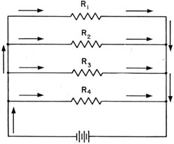
Figure 25.-Resistances in parallel.
Electrical resistances in parallel work the same way.
Suppose the four resistances in figure 25 are of 100 ohms
each. The total resistance of the circuit will be 1/4 of
100, or 25 ohms. The total opposition will be only 1/4
that of a single resistor.
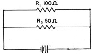
Figure 26.-Two unequal resistances in parallel.
30
Unfortunately, the resistances in parallel circuits are
frequently not equal. Look at figure 26. Two UNEQUAL
values are indicated.
Since R1 is 100 ohms and R2 50, the total resistance
naturally will be less than the smaller-but how much?
There are several ways of finding the total resistance,
but the easiest is to use the following formula-
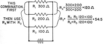
Sometimes you will find three or more unequal resistances in parallel. To find the total resistance in such a
circuit, proceed as indicated in figure 27.
Figure 27.-Three unequal resistances in parallel.
First, find the combined resistance of R1 and R2. This
gives you the sub-total, RX, equal to 120 ohms. Then
combine RX with R3 in the same manner to obtain RT of
54.5 ohms.