CHAPTER 22 NAVY TRANSMITTERS WHY YOU TUNE A TRANSMITTER
You TUNE a transmitter to get MAXIMUM POWER from
the transmitter into the antenna. This can be likened
somewhat to adjusting a heating plant to get the maximum amount of heat into the radiators.
You adjust a heating plant by opening and closing
valves which regulate the fuel and air supply. If these
are not in PROPER PROPORTIONS, you don't get maximum
heat. Also, if some of the valves in the steam line are
opened too widely, and others closed too tightly, the radiators can't do their best job of heating. Suppose you want
to turn down the heat. There are two common ways of
doing this-turn off the radiator, or reduce the fuel input
to the boilers.
Now notice the comparison between a heating plant
and a transmitter. The POWER (fuel) to operate the
transmitter might be considered the pilot that STARTS the
transmitter's operation. Now, unless the CORRECT
237
ADJUSTMENTS of all the stages between the oscillator and
antenna are made, little or none of the energy from the
power lines will get into the antenna and be radiated as
electromagnetic energy. It's TUNING that does the trick.
WHAT IS TUNING?
A transmitter is tuned by setting each stage of the
transmitter to the frequency of oscillations generated by
the oscillator. Here is how this procedure works out.
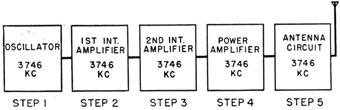
You are instructed to tune up on a frequency of 3,746
kilocycles. Follow the steps shown in figure 158. The
Figure 158 -Order of tuning steps for a transmitter.
FIRST step is to set the OSCILLATOR TUNING DIALS to the
position, indicated on the calibration card, where a frequency of 3,746 kilocycles will be generated.
Next, step 2, tune the stage following the oscillator to
the same frequency, 3,746 kcs. The 2ND INT. AMPLIFIER, step 3, is next tuned to a frequency of 3,746 kcs.,
followed by the POWER AMPLIFIER stage, and then the
ANTENNA CIRCUIT.
Briefly, here's the routine of tuning the AF STRAIGHT
THROUGH transmitter, one that has EACH STAGE tuned to
the frequency of the oscillator-first tune the oscillator
to the right frequency, and then tune each successive
stage after the oscillator to the frequency of the PRECEDING stage.
RESONATING A STAGE
TUNING a stage to the desired frequency is sometimes
called RESONATING the stage. Thus the expressions
238
TUNING the stage and RESONATING the stage may be used
to say the same thing.
The RESONANT FREQUENCY of a stage is the FREQUENCY
at which it will oscillate. You have had many contacts
with RESONANT frequencies. Recall your experience with
an automobile. When driving at a certain speed, certain
RATTLES and VIBRATIONS would be present. At other
speeds, different vibrations and other rattles appeared.
It seemed that every speed had its own rattle, and, by
knowing your rattles, you could tell your speed.
Why did certain rattles and vibrations appear at one
speed and not at others? Because the automobile, when
traveling at one speed, produced the frequencies of vibration of some rattles but not of others. At other speeds,
other frequencies of vibration were produced.
Similarly, if the oscillator is generating a radio frequency current of 2,136 kc., and the following stage is
tuned to 2,251 kc. the stage following will not vibrate, or
oscillate, until the oscillator frequency is RAISED to 2,251
kc., or the stage following is REDUCED to 2,136 kc.
In RESONATING a stage, you adjust the variable inductance, or condenser, until the RESONANT frequency of the
stage is the same as the one preceding it.
INDICATORS OF RESONANCE
How do you know when a stage is tuned to resonance?
The METERS on the operating panel of the transmitter
tell you.
Two general classes of meters are used with transmitters-GRID CURRENT meters showing the current flow
in the grid circuits, and PLATE CURRENT meters that indicate the current flowing in the plate circuits. In addition, most transmitters have an ANTENNA CURRENT
meter to show the current in the antenna circuit.
Here is a general rule for using the meters-GRID current meters show resonance by a MAXIMUM indication,
while PLATE CURRENT meters show resonance with a MINIMUM
239
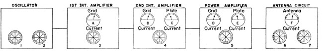
Figure 159.-Tuning dials and meters of a typical transmitter.
240
indication. Resonance in ANTENNA CIRCUITS is
revealed by a MAXIMUM reading also. Don't be surprised
if no indication at all appears. The reason for this will
be explained later. Figure 159 is a typical arrangement
of the meters found in one of the Navy's transmitters.
The tuning controls in figure 159 are indicated by
the numerals 1 to 7. They may be marked as follows-
The first step in tuning this arrangement is to set dial
1 to the desired frequency. You will do this by referring
to the calibration card, and checking against a FREQUENCY
METER. More about this later.
Next, adjust dial 2, until a MAXIMUM indication is
obtained on meter A. That shows the OSCILLATOR stage
to be TUNED to RESONANCE.
Now, adjust dial 3, until a MAXIMUM indication is obtained on meter B. The 1ST INT. AMPLIFIER is now tuned
to resonance.
Adjust dial 4 until a MINIMUM reading is obtained on
the PLATE CURRENT meter C. When this is done, a MAXIMUM deflection will be obtained on GRID CURRENT meter
D. You have now tuned the 2ND INT. AMPLIFIER to
resonance.
Finally, you adjust dial 5, until a MINIMUM indication
is obtained on PLATE CURRENT meter E. The power amplifier has also been tuned to resonance.
Notice again how each GRID CURRENT meter gave a
MAXIMUM indication, while the PLATE CURRENT meter
gave a minimum indication as the stages were tuned to
resonance.
241
RESONATING THE ANTENNA CIRCUIT
Resonance indications in the antenna circuit vary with
the type of TRANSMITTER, the FREQUENCY of emission, the
LENGTH and TYPE of antenna used. Resonance in the
antenna circuit is sometimes indicated by a MAXIMUM
ANTENNA current and at other times by a RISE in the
POWER AMPLIFIER PLATE CURRENT, meter E.
Here is the procedure-after tuning the POWER AMPLIFIER to resonance, INCREASE slightly the setting of CONTROL 6, ANTENNA COUPLING. Adjust ANTENNA TUNING,
dial 7, until a MAXIMUM antenna current is shown on
meter F. If an indication on meter F CANNOT be OBTAINED, resonance in the ANTENNA CIRCUIT will have
been achieved when the POWER AMPLIFIER PLATE CURRENT,
meter E, stops rising. Remember these two types of
indications. You will use both of them.
When the ANTENNA CIRCUIT has been resonated, INCREASE the SETTING of the ANTENNA COUPLING, dial 6,
until the POWER AMPLIFIER PLATE CURRENT meter E indicates approximately the proper OPERATING current. READJUST controls 5 and 7 slightly as you increase the
setting of control 6, until the proper POWER AMPLIFIER
PLATE CURRENT is obtained.
Tuning the power amplifier and antenna requires considerable practice and much care. Remember that it
varies from set to set, from one frequency to another,
and with the conditions of the seas.
OVERCOUPLING OF POWER AMPLIFIER TO ANTENNA
In tuning, one mistake easily made is to increase the
coupling between the POWER AMPLIFIER and ANTENNA
CIRCUIT too much. When this happens, the POWER AMPLIFIER stage is detuned, and efficiency goes down. The
table on page 283 tells how you may check for the presence of OVERCOUPLING. When you find it, reduce the
coupling.
242
LOADING UP A STAGE
LOADING UP A STAGE is an expression you will frequently hear in connection with tuning a transmitter.
Refer back to the adjustment of dial 2 in figure 159.
When this dial was set to resonance as indicated by a rise
in GRID CURRENT of METER A, you performed the task of
LOADING UP the 1ST INT. AMPLIFIER STAGE. Also, when
you resonated the 1ST INT. AMPLIFIER STAGE by adjusting
dial 3, you LOADED UP the 2ND INT. AMPLIFIER STAGE.
Occasionally you will find it impossible to load up a
following stage by resonating the preceding one. The
common cause of this failure is lack of coupling between
the preceding and following stages. When this happens,
call a technician.
OPERATING WITH REDUCED POWER
Often it is desirable to operate the transmitter at less
than full power. Some transmitters have special switching arrangements to cut out the last amplifier stage and
couple the antenna circuit directly to the 2nd intermediate amplifier. The TBK is an example of this type
of transmitter.
Other transmitters require that you reduce the coupling between the power amplifier and antenna circuits.
This practice has the effect of permitting less energy to
reach the antenna. Remember? This is like turning
down a steam valve on a radiator.
Some transmitters allow you to reduce power by
turning down the voltage applied to the power amplifier.
This method of reduction is more like cutting down heat
at the radiator by reducing the fuel supply to a boiler.
It is very important that you know the permissible
methods of reducing the output power. Check the instruction books to gain this information.
243
HARMONICS
You were briefly introduced to the subject of harmonics in chapter 18 on receivers. Now you will get a
fuller story of what they are.
You recall that a bell, or tuning fork, gives out a note
of the same pitch each time you strike it. If you could
take the sound waves apart and examine them, you would
find that instead of a single note of one frequency being
present, there are several notes of different frequencies.
The note with the LOWEST frequency-usually the
STRONGEST note-is called the FUNDAMENTAL, Or the
FIRST HARMONIC. As an example, say the fundamental
frequency is 500 cycles. Oddly enough, the note with
the next higher frequency will have exactly TWICE the
frequency of the FIRST HARMONIC, or-500 X 2 = 1,000
cycles. And the frequency of the THIRD HARMONIC will
be 3 times the frequency of the first harmonic-500 X 3 = 1,500 cycles. And so on.
This SERIES of HARMONICS goes on up indefinitely, becoming weaker and weaker until their intensity is too
weak to be recorded.
Oscillators used with radio circuits also produce a
series of harmonic frequencies. For example, if an
oscillator has a first harmonic of 2,500 kc., it also has a
series of harmonics following it-
Notice how these harmonics are used in the next
section.
FREQUENCY MULTIPLYING
-
It is easier to design and build a stable oscillator for
low frequencies than it is for high frequencies. In addition, if crystals are used to control the oscillator
244
frequency, the crystals for very high frequencies must be
ground so thin that they would easily crack while vibrating.
To overcome this difficulty, oscillators are made to
generate a relatively low 1st HARMONIC. The high frequencies are obtained by making the following stages
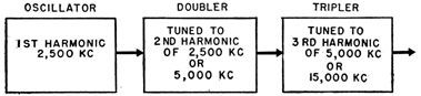
Figure 160.-Frequency multiplying.
tune to HIGHER HARMONICS, such as the second or third.
The practice is known as FREQUENCY MULTIPLYING.
Here is how it is done.
In figure 160, the oscillator is tuned to the first harmonic, 2,500 kc. The next stage, the DOUBLER, is tuned
to the SECOND HARMONIC, 5,000 kc.
In the doubler stage, the 5,000 kc frequency ALSO HAS
HARMONICS, and as far as the next stage, the tripler, is
concerned, the 5,000 kc. frequency can again be considered the FIRST HARMONIC. Therefore, the tripler stage
may be tuned to the THIRD harmonic of 5,000 kc.-15,000
kc. Thus, the output of the tripler stage is SIX times the
frequency of the oscillator-
2,500 kc. X 6 = 15,000 kc.
You will find this system of frequency DOUBLING and
TRIPLING used with several Navy transmitters. Sometimes, the oscillator is followed by a tripler, and then
by a doubler stage. The operation is the same whichever
the case may be.
PICKING THE CORRECT HARMONIC
The use of frequency multiplying makes it very important for you to understand that an oscillator has MANY
HARMONICS. Here is why.
245
If you tune the doubler stage to the WRONG harmonic,
the frequency of transmission will be wrong. You can
easily do this because some transmitters can be tuned to
the WRONG harmonic as easily as to the correct one. The
TBK series is an example of such a transmitter.
Systems of PICKING and COUNTING the harmonics can
easily be developed with the aid of an experienced operator. But until you have developed this technique, you'd
better practice resonating the stages VERY CLOSE to the
position indicated on the calibration card.
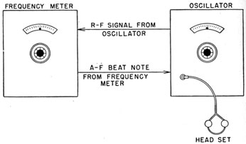
FREQUENCY METER
Frequency meters are just ACCURATELY CALIBRATED
OSCILLATORS. You use them to check the frequency of
the transmitter oscillator. Briefly, here is what a frequency meter does.
When you wish to check the transmitter's frequency,
you first set the frequency meter ACCURATELY to the
desired frequency.
Figure 161.-Use of the frequency meter.
An r.f. signal from the oscillator, as illustrated in the
figure, is then fed into the frequency meter. The
signal from the frequency meter is BEAT against the signal
from the oscillator. If the OSCILLATOR frequency is EXACTLY
246
the same as the signal of the FREQUENCY meter, no
audio beat note will be heard in the HEADSET. But if the
oscillator frequency is slightly higher or lower, a whistling note will be heard.
The next step is to adjust the oscillator tuning control
slightly until the BEAT NOTE DISAPPEARS. The oscillator
is now tuned to the correct frequency-you can turn the
frequency meter off, and proceed with the tuning of the
transmitter.
Be careful that you DO NOT beat a higher OSCILLATOR
HARMONIC against the frequency meter, because it, too,
will give a ZERO BEAT. That is why it is wise always to
set the OSCILLATOR TUNING DIAL as near to the correct
frequency as possible by referring to the calibration card.
The way the frequency meter is coupled to the transmitter varies greatly from one installation to another.
Therefore, it will be necessary for you to get an experienced operator to explain your setup.
NAVY TRANSMITTERS
The Navy transmitters discussed in the following sections are representative of the most common installation s. Probably you will not find all models on your
ship, but it is possible. At least, if you are transferred
from ship to ship, you certainly will come in contact with
most of them.
The information given for each model is extremely
brief. It is little more than an introduction to the sets.
Therefore, it is well to refer often to the INSTRUCTION
BOOKS for more complete information.
THE TBK-TBM TRANSMITTING EQUIPMENT
The TBK-TBM transmitters are similar in both construction and general appearance. But they differ in
that the TBK is intended for C.W. transmission only,
while the TBM is provided with a separate MODULATOR
for voice M.C.W. communication.
The similarity in construction and design makes it
possible to use a single set of instructions for placing
247
either transmitter in operation. However, remember
that individual differences in the two models must be
taken into consideration when the equipment is being
tuned or adjusted.
Both the TBK and TBM are capable of tuning over a
frequency band from 2,000 to 18,100 kilocycles. The full
power output is about 500 watts at low frequencies,
gradually decreasing to 300 watts at 18,100 kilocycles.
The frequency of the transmitter controlled by an
electron-coupled, master oscillator, followed by doubler
stages. The oscillator itself tunes over a range of 1,000
to 2,262.5 kilocycles. The first intermediate stage operates as a STRAIGHT-THROUGH amplifier up to 4,000 kilo-cycles, and as a doubler for frequencies from 4,000 to
9,050 kilocycles. Frequencies above 9,050 kilocycles are
obtained by doubling in the SECOND intermediate amplifier. The power amplifier stage operates as a straight-through amplifier over the entire frequency range.
Extreme care must be exercised in tuning the TBK-TBM transmitters not to tune any of the stages to the
wrong harmonic. That is especially true in tuning the
DOUBLER CIRCUIT. The final setting of the tuning dials
will be within a very few scale divisions of the settings
indicated on the calibration card.
Provisions are made for low power operation with a
nominal output of 75 watts in the range of 2,000 to 9,050
kilocycles. You do this by switching the final amplifier
out of the transmitter circuit, and connecting the 2nd
intermediate output directly to the antenna circuit.
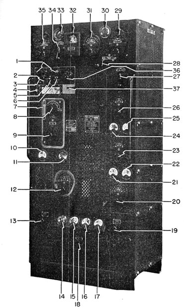
Legend for Figure 162.
1. INDICATOR LIGHTS
Five lights-STARTING SOLENOID, PLATE VOLTAGE, HEATER CURRENT, BIAS VOLTAGE, and M. O. FILAMENT.
2. MASTER OSCILLATOR STAND-BY FILAMENT POWER SWITCH
This switch energizes the M. O. filaments when the rest of the transmitter is off.
3. TEST KEY.
This control has the same effect as closing a telegraph key. You use it when tuning the transmitter.
248
Figure 162.-The TBK-TBM transmitter.
699198°-46-17
249
4. FREQUENCY METER AUDIO OUTPUT JACK.
The output jack for the headphones when you are using the frequency meter.
5. START-STOP SWITCH
Turns the transmitter ON and OFF.
6. REMOTE-LOCAL CONTROL
Switches the control of the transmitter to either REMOTE or LOCAL operating station.
7. THERMOMETER
Indicates the temperature inside the M. O.
heat chamber.
8. MASTER OSCILLATOR RANGE SWITCH, control A.
An eight-point switch used to select the correct inductance for the desired frequency.
9. MASTER OSCILLATOR TUNING CONTROL B.
This control adjusts the variable condenser in the oscillator tank circuit.
10. M. O. SCREEN GRID CURRENT METER.
Indicates the current flowing in the screen grid circuit of the M. O.
11. M. O. PLATE CURRENT METER
Indicates the current flowing in the M. O. plate circuit.
12. DOUBLER CIRCUIT TUNING CONTROL C.
Control C tunes the doubler circuit following the M. O.
13. FILAMENT VOLTAGE CONTROL
This control regulates the filament voltages.
14. FILAMENT VOLTAGE METER
Indicates the filament voltage. Should indicate 10 volts.
15. P. A. HOURS
This meter indicates the number of hours the power amplifier has been in operation.
16. BIAS VOLTAGE METER
Indicates the bias voltage applied to the amplifier tubes.
17. P. A. PLATE VOLTAGE METER
Indicates the power amplifier plate voltage.
18. OVERLOAD RELAY RESET
Manual reset for the overload protective relay.
19. GENERATOR FIELD.
Controls the voltage being applied to the field of the motor-generator. If the plate voltage is too low, this control is turned up.
250
20. 1ST INTERMEDIATE AMPLIFIER TUNING CONTROL D
Tunes the 1st Intermediate amplifier.
21. 2ND INT. AMP. GRID CURRENT METER
Indicates the current flowing in the 2nd intermediate amplifier grid circuit.
22. 1ST INTERMEDIATE AMPLIFIER PLATE CURRENT METER
Indicates the plate current flowing in the 1st intermediate amplifier circuit.
23. 2ND INTERMEDIATE AMPLIFIER TUNING CONTROL E
Tunes the 2nd intermediate amplifier stage.
24. P. A. GRID CURRENT
Indicates the grid current flowing in the power amplifier stage.
25. 2ND INTERMEDIATE AMPLIFIER PLATE CURRENT METER
Indicates the plate current flowing in the plate circuit of the 2nd intermediate amplifier.
26. POWER AMPLIFIER TUNING CONTROL F.
Tunes the power amplifier stage.
27. POWER, HIGH-LOW SWITCH
Connects and disconnects the power amplifier stage to the antenna circuit.
28. FREQUENCY RANGE CONTROL L.
A two-position switch-2,000-4,000 and 4,000-18,100 kilocycles.
29. ANTENNA COUPLING CONTROL H
This control adjusts the degree of coupling between the P. A. and antenna circuits.
30. P. A. PLATE CURRENT METER
Indicates the current flowing in the power amplifier plate circuit.
31. ANTENNA TUNING CAPACITOR CONTROL J.
This control adjusts the variable condenser in the antenna coupling circuit.
32. KEYING RELAY
This is the relay that "keys" the transmitter.
33. ANTENNA CURRENT METER
Indicates the R.F. current flowing in the antenna circuit.
34. ANTENNA COUPLING
A two-position switch; connects the antenna tuning circuit to the antenna for either a CURRENT or VOLTAGE feed system.
251
35. ANTENNA TUNING INDUCTANCE CONTROL K.
This control adjusts a variable inductance in the antenna circuit.
36. TUNE-OPERATE SWITCH
The use of this switch is explained in tuning procedure.
37. EMERGENCY SWITCH
This switch is used for an emergency shutdown of the transmitter.
OPERATION OF THE TBK-TBM TRANSMITTERS
GENERAL
1. The lettered controls (A) through (L) are used in
TUNING the transmitter. You will use them in
ALPHABETICAL ORDER. The meters accompanying
the controls indicate when the dials have been
properly set.
2. The tuning of all stages, especially the doubler,
requires extreme care-you may tune up on the
WRONG HARMONIC. Usually you will find the final
dial settings to be within a very few scale divisions
of the positions indicated on the calibration card.
If you find considerable error in the final settings,
call someone to check your work.
3. The routing followed in resonating and loading
the antenna circuit is subject to considerable variation . It depends upon the frequency of transmission, length of the antenna, and the condition of the
sea (whether the ship is rolling and pitching or
not) . Therefore, the procedure given here for
tuning the antenna circuit is a suggested procedure rather than an absolute pattern to follow.
TUNING PROCEDURE FOR HIGH POWER CW. EMISSION
1. Set the following controls and switches in the indicated positions.
CONTROL
POSITION
START-STOP
STOP
LOCAL-REMOTE
LOCAL
TUNE-OPERATE
TUNING, STEP 1
252
EMERGENCY SWITCH
ON
ANTENNA COUPLING, CONTROL H.
NEAR ZERO
LETTERED CONTROLS, A through L.
To POSITIONS INDICATED ON CALIBRATION CHART for the desired frequency.
2. Press START button. Adjust GENERATOR FIELD rheostat until plate voltage meter indicates 1,000 volts.
Adjust FILAMENT VOLTAGE control until filament
meter indicates 10 volts.
3. Set the FREQUENCY METER to the correct frequency.
If the frequency meter is coupled to the grid circuit
of the master oscillator stage, the frequency meter
must be set on the master oscillator frequency.
Should the frequency meter be coupled to the output plate circuit of the master oscillator, the frequency meter must be set on TWICE the master
oscillator frequency. (Check this coupling system
with your chief.)
4. Insert headphone jack in FREQUENCY METER output
jack, and adjust MASTER OSCILLATOR, tuning control
B, until zero beat is obtained. Be sure you are on
the CORRECT harmonic. It will be very close to the
setting indicated on the calibration card.
5. Operate TEST KEY. The M. O. PLATE CURRENT
should be about 60 ma., and M. O. SCREEN CURRENT
near 11 ma.
6. Turn the TUNE-OPERATE switch to TUNING, STEP 2.
Increase GENERATOR FIELD rheostat until PLATE
VOLTAGE METER indicates 2,000 volts.
7. Operate TEST KEY and adjust DOUBLER, control C,
until a maximum indication is obtained on the 1st
INT. AMP. PLATE CURRENT meter. The final setting of this control should be within 2 or 3 scale
divisions of the position indicated on the calibration card.
8. With test key depressed, tune the 1st INT. AMP.,
253
control D, to resonance. It will be indicated by a
maximum indication on the 2nd INT. AMP. GRID
CURRENT meter. Be sure you are on the correct
harmonic. It will be close to the indicated setting.
9. With the TEST KEY depressed, tune the 2nd INT.
AMP., control E, to resonance. It will be indicated
by a maximum indication of the P. A. GRID CURRENT
meter.
PRECAUTION: Observe the P. A. PLATE CURRENT.
If it becomes excessively high, reduce the plate
voltage by turning the GENERATOR FIELD rheostat
counterclockwise.
10. Adjust POWER AMPLIFIER TUNING, control F, until a
minimum indication is obtained on the P. A. PLATE
CURRENT meter.
11. Tune the antenna circuit to resonance by varying
the ANTENNA TUNING CAPACITOR, control J, and
ANTENNA TUNING INDUCTANCE, control K, until a
rise in P. A. PLATE CURRENT is indicated. At this
point, an indication of current may also be observed
on the ANTENNA CURRENT meter.
12. If resonance cannot be obtained, move the ANTENNA
FEED, Control F, to the OTHER position, that is,
CURRENT to VOLTAGE, or VOLTAGE to CURRENT. repeat the tuning procedure outlined in step 11. If
you still fail to obtain resonance, increase the setting of the ANTENNA COUPLING, control H, and repeat steps 11 and 12.
13. If the P. A. PLATE CURRENT meter indicates over
150 ma., reduce ANTENNA COUPLING, control H, and
readjust control K, until the minimum P. A. PLATE
CURRENT is just slightly less than 150 ma.
14. Set the TUNE-OPERATE switch on OPERATE, and increase GENERATOR FIELD rheostat, until the PLATE
VOLTAGE meter indicates 3,000 volts.
15. Close TEST KEY and readjust ANTENNA TUNING
capacitor, control J, for a maximum indication on
the ANTENNA CURRENT meter. (See NOTE.)
254
At the same time readjust the ANTENNA COUPLING,
control H, to keep the P. A. PLATE CURRENT from
exceeding 350 ma. While these adjustments are
being made, it may be necessary to readjust slightly
the P. A. TUNING, control F, to obtain a MINIMUM
indication on the P. A. PLATE CURRENT meter.
NOTE: Sometimes it is impossible to obtain an
ANTENNA CURRENT indication. In such cases, it is
necessary to use the P. A. PLATE CURRENT as an
indication of resonance. When the P. A. PLATE
circuit has been tuned to resonance, ANTENNA
RESONANCE will be indicated by a rise in P. A.
PLATE, CURRENT to a maximum value. Be very sure
that the rise in power amplifier plate current is not
due to DETUNING the power amplifier stage.
16. Check for the presence of overcoupling, using the
procedure outline on page 283.
ADJUSTMENTS FOR LOW POWER OPERATION
1. Place TUNE-OPERATE switch in TUNING 2 position.
Throw the HIGH-LOW POWER switch to LOW position.
This action disconnects the POWER AMPLIFIER for
the circuit, making the 2nd INT. AMPLIFIER the final
amplifier stage.
2. Return TUNE-OPERATE switch to OPERATE position
and adjust ANTENNA COUPLING, control H, until the
2nd INT. AMP. PLATE CURRENT does not exceed 150
ma. Reducing coupling may also make it necessary to retune slightly the 2nd INT. AMP. PLATE
circuit for a minimum 2nd INT. AMP. PLATE
CURRENT indication.
REMOTE OPERATION
1. When the transmitter has been tuned, place the
REMOTE-LOCAL switch in REMOTE position. The
transmitter can be started, stopped, and keyed
from remote stations. When returning or adjusting, it is always best to return the control to LOCAL.
255
THE TBM MODULATOR EQUIPMENT
The TBM transmitter can be operated independently
of the modulator unit. However, when the transmitter
is installed with the modulator, the mode of transmission-C.W., M.C.W., or VOICE-is determined by the setting of the EMISSION SELECTOR switch on the modulator
unit.
When the EMISSION SELECTOR is set in C.W. position,
the operation of the transmitter is independent of the
modulator's controls. Start, time, and adjust the transmitter as outlined in the preceding section.
When you are preparing the TBM for M.C.W. and
VOICE transmission, reduce the P. A. PLATE CURRENT of
the transmitter from 350 to 270 ma., by decreasing the
setting of the ANTENNA COUPLING, control H. The modulator is started and stopped simultaneously with the
transmitter.
HOW TO ADJUST MODULATOR FOR M.C.W. OPERATION
1. Turn C.W.-M.C.W.-VOICE switch to VOICE.
2. Operate TEST KEY on transmitter, and readjust
ANTENNA COUPLING, control H, until P. A. PLATE
CURRENT is not over 270 ma.
3. Turn C.W.-M.C.W.-VOICE switch to M.C.W., and
key as desired from a local or remote station,
as designated by the setting of the REMOTE-LOCAL CONTROL switch on transmitter.
4. Check the modulator's meter readings against the
chart on page 259 to determine whether the set
is operating properly.
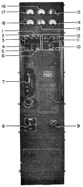
Legend for Figure 163.
1. PLATE VOLTAGE INDICATOR LIGHT
Indicates whether or not plate voltage is being applied to the modulator.
2. BIAS VOLTAGE INDICATOR LIGHT
Indicates the presence of bias voltage.
3. STARTING SOLENOID INDICATOR LIGHT
Indicates the starting switch is closed.
256
Figure 163.-Modulator for TBK-TBM transmitter.
257
4. AUTOMATIC-MANUAL GAIN SWITCH
This control is intended to eliminate the necessity for the operator continually to increase and decrease the SPEECH GAIN attenuator. Usually the ship and background noise is too great to permit its use.
5. TALK SWITCH
A three-position switch. In the up position it acts as a key. In the DOWN position, it closes the proper circuits for VOICE transmissions. In the MIDDLE position, the switch is OFF.
6. CARRIER CONTROL SWITCH
Usually set in MANUAL position because background noises are too great to permit use of AUTOMATIC GAIN.
7. TEST HAND SET
Microphone and receiver used in testing the modulator and transmitter.
8. EMISSION SELECTOR
Selects the type of emission, C.W., M.C.W., or VOICE.
9. FILAMENT VOLTAGE RHEOSTAT
Adjusts the voltage applied to the filaments of the modulator tube.
10. VOICE RELAY ATTENUATOR
Seldom used since AUTOMATIC GAIN does not work well.
11. RECEIVER VOLUME ATTENUATOR
Controls the volume of sound coming from the receivers.
12. SPEECH GAIN ATTENUATOR
Gain control for microphone input to modulator. This control is adjusted to get correct degree of modulation.
13. INTERMEDIATE AMPLIFIER PLATE CURRENT METER
It does what its name indicates.
14. FILAMENT VOLTAGE METER
Indicates the filament voltage.
15. PERCENTAGE MODULATION METER
Indicates the percentage of modulation present.
16. MODULATOR PLATE CURRENT METER
Indicates the plate current flowing in one of the push-pull tubes of the last stage.
17. MODULATOR PLATE CURRENT METER
Same at 16.
18. INPUT AMPLIFIER PLATE CURRENT METER
Indicates plate current flowing in the first amplifier stage.
258
TYPICAL MODULATOR METER INDICATIONS
M.C.W. Operation
VOICE MODULATION; MANUAL - AUTOMATIC GAIN SWITCH IN MANUAL position
Key up
Key down
0% Modulation
100% Modulation
INPUT AMPLIFIER PLATE CURRENT METER (19)
0
0
3
3
INTERMEDIATE AMPLIFIER PLATE CURRENT METER (14)
120
130
120
140
MODULATOR PLATE CURRENT METER (17)
50
160
50
160
PERCENTAGE OF MODULATION METER (16)
60
60
0
100
FILAMENT VOLTAGE METER (15)
10
10
10
10
MODULATOR PLATE CURRENT METER (18)
50
160
50
160
How TO ADJUST TRANSMITTER FOR VOICE OPERATION
1. Turn C.W.-M.C.W.-VOICE switch to VOICE position. Operate TEST KEY on transmitter, and reduce P.A. PLATE CURRENT to 270 ma. by decreasing the ANTENNA COUPLING, control H.
2. Remove HANDSET from microphone hook. Place CARRIER CONTROL switch in MANUAL position. Press the button on the handset and talk into the microphone.
3. Adjust SPEECH GAIN attenuator until PERCENTAGE
MODULATION meter indicates the transmitter is being modulated.
4. Do not increase the SPEECH GAIN attenuator beyond a point where the PERCENTAGE OF MODULATION
259
meter indicates 60 percent when the syllable, "Ah"
is spoken normally into the microphone held one
inch from the lips. This setting is used to prevent
instantaneous over-modulation on certain expressions.
5. Check the level of sound being received from the
receiver. If too low, increase the RECEIVER VOLUME
ATTENUATOR.
6. Turn the transmitter's REMOTE-LOCAL CONTROL
switch to REMOTE-the transmitter is set for remote operation.
7. Check the meters on the modulator to see that they
do not materially exceed the values given in the
chart on page 259.
8. Set MANUAL-AUTOMATIC GAIN switch in AUTOMATIC
position. This eliminates the need for further adjustments of the SPEECH GAIN ATTENUATOR.
9. Suppose the operator stationed at the MODULATOR
desires to exercise control over the remote stations.
He can do so by removing the TEST HANDSET from
the hook, or by moving the CARRIER CONTROL switch
to MANUAL and the TALK switch to OFF. By doing
this, the operator can cut off all transmissions from
remote stations.
THE TBL RADIO TRANSMITTING EQUIPMENT
The TBL radio transmitting equipment has two different operating panel arrangements. This feature gives
the impression that the two types are quite different in
circuit design, but actually they are very similar. Models
4, 8, and 9 have one panel arrangement, and 5, 6, 10, and
11 have another. Careful examination of the controls on
the two panels will reveal their identity.
Models TBL 10 and 11 are intended primarily for shore
installations. The others are intended for smaller surface craft and submarines. In this discussion, only the
TBL 5-6 is considered.
The TBL 5-6 is actually two transmitters in a single
cabinet. The INTERMEDIATE FREQUENCY section, 175 to
260
600 kc., occupies the portion of the cabinet to your right,
and the HIGH FREQUENCY section, 2,000 to 18,100 kc., the
portion to your left.
Unlike the TDE transmitting equipment, the TBL sets
use common vacuum tubes for all stages of both sections
except MASTER OSCILLATORS. The tuning inductances and
capacitors belonging to individual circuits are separate.
A TRANSFER SWITCH changes the vacuum tube connection
from one transmitter section to the other. When the
TRANSFER SWITCH is in either position, the controls of
one section are inoperative.
All TBL transmitting sets may be used for C.W.,
M.C.W., or VOICE communication. When VOICE transmission is desired, a Navy Type CRV 50064 speech input
equipment must be used.
The nominal output power is 200 watts on C.W., 100
watts for M.C.W., and 50 watts on VOICE. You may reduce the power output on C.W. transmission by turning
the plate voltage control counterclockwise, or by decreasing the coupling between the power amplifier and
antenna circuits. On M.C.W. and VOICE, it is advisable to
reduce the power by decreasing the ANTENNA COUPLING.
A unique method is used to indicate the controls that
govern the individual transmitter circuits. The L.F. CONTROLs have a BLUE background, and the H.F. controls a
GREEN background. The lettered controls B through M
are used to tune the H.F. section, and N through V the
I.F. section. Control A is the H.F.-I.F. TRANSFER SWITCH,
and W the ANTENNA TRANSFER SWITCH.
COMMON CONTROLS
1. START-STOP SWITCH
Local switch to start or stop the transmitter.
2. REMOTE-LOCAL SWITCH
Designates the location of the control. When this switch is in REMOTE position, the transmitter can be started or stopped from remote stations.
3. LINE VOLTAGE, NORMAL-HIGH
This switch is used to connect protecting circuits into the temperature control
261
circuits. This switch is placed in HIGH position whenever the line voltage is greater than normal. (D.C. sets only.)
4. OVERLOAD RELAY RESET
Reset the overload relay after it has opened.
5. INDICATOR LIGHTS
MOTOR SOLENOID (BLUE) PLATE VOLTAGE (RED) HEATER POWER (AMBER) BIAS VOLTAGE (GREEN)
6. PHONE-C.W.-M.C.W. SWITCH
Sets the type of emission.
7. PLATE VOLTAGE RHEOSTAT
Adjusts the voltage applied to the amplifier tubes.
8. FILAMENT VOLTAGE RHEOSTAT
Regulates the voltages applied to the vacuum tube filaments.
9. M.O. HEAT CHAMBER THERMOMETER
Indicates the temperature in the M.O. heat chamber.
10. TEST KEY
This switch is used to test the operation of the transmitter while you are tuning it.
11. FREQUENCY METER AUDIO OUTPUT JACK
A jack for a pair of head phones to be used in checking the frequency of the transmitter against a frequency meter.
12. EMERGENCY, ON-OFF SWITCH
A switch that can be used to turn the transmitter off in emergency.
13. P.A. GRID CURRENT SWITCH
A two-position switch. To RAISE and to LOWER the grid currents.
14. TUNE-OPERATE SWITCH
A three-position switch-TUNE 1, TUNE 2, and OPERATE. This switch protects the transmitter from damage and undesirable transmissions while tuning is in progress.
15, 16. CALIBRATION CHARTS
Indicates the dial settings for the various frequencies.
A. TRANSFER SWITCH, H.F.-L.F.
Transfers the power from one transmitter section to the other.
W. ANTENNA TRANSFER SWITCH L.F.-H.F.-RECEIVER
This is the switch that connects the antenna to one section of the transmitter, or receiver.
HIGH FREQUENCY SECTION-TUNING CONTROLS
B. MASTER OSCILLATOR RANGE
An eight-position switch used to set the
frequency range for the master oscillator.
262
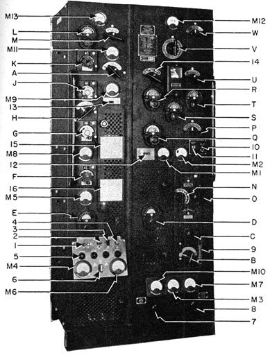
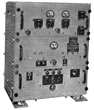
Figure 164.-The TBL-5 transmitter.
C. MASTER OSCILLATOR TUNING
A variable inductance that selects the frequency within the frequency range determined by the setting of control B.
D. DOUBLER CIRCUIT TUNING
This control tunes the grid circuit of the first intermediate amplifier stage.
263
E. 1st INTERMEDIATE AMPLIFIER TUNING
Tunes the plate circuit of the 1st intermediate amplifier stage.
F. 2nd INTERMEDIATE AMPLIFIER TUNING
This control tunes the plate circuit of the 2nd intermediate amplifier.
G. POWER AMPLIFIER TUNING
Tunes the plate circuit of the power amplifier stage.
H. RANGE SWITCH
Selects the frequency range for the tuning of the intermediate and power amplifier stages.
J. ANTENNA COUPLING CONTROL
Sets the degree of coupling between the power amplifier and antenna circuits.
K. ANTENNA TUNING INDUCTANCE
This control adjusts a variable inductance in the antenna circuit.
L. ANTENNA CAPACITOR
This control adjusts a variable capacitor in the antenna circuit.
M. ANTENNA FEED SWITCH
A two-position switch. Selects either CURRENT or VOLTAGE feed, depending on the length of the antenna and the frequency of the transmitter.
LOW FREQUENCY SECTION-TUNING CONTROLS
N. MASTER OSCILLATOR RANGE
A seven-position switch that sets the frequency range for the master oscillator.
O. MASTER OSCILLATOR TUNING
A variable inductance that tunes the oscillator within the frequency range determined by the setting of control N.
P. RANGE SWITCH
A five-position switch that selects the frequency range for the tuning of the intermediate and power amplifier stages.
Q. INTERMEDIATE AMPLIFIER TUNING
Tunes the plate circuit of the intermediate amplifier plate circuit.
R. POWER AMPLIFIER TUNING
This control tunes the plate circuit of the power amplifier stage.
S. ANTENNA COUPLING
Sets the degree of coupling between the power amplifier and antenna circuits.
T. ANTENNA TUNING
Adjusts a variable inductance in the antenna circuit. This control is used in conjunction with control V.
U. ANTENNA SERIES CAPACITOR
A two-position switch. It connects IN, or shorts OUT, a series condenser in the
264
antenna circuit. This antenna permits you to use higher frequency antennas on this low frequency range.
V. ANTENNA INDUCTANCE
A 15-position switch that connects the desired amount of inductance into the antenna circuit. It is used in connection with control T.
METERS ON THE TBL 5 TRANSMITTING EQUIPMENT
M1. H.F., M.O., SCREEN CURRENTS
Indicates H.F. master oscillator screen current.
M2. H.F., M.O., PLATE CURRENT
Indicates the H.F. master oscillator plate currents.
M3. MASTER OSCILLATOR PLATE VOLTAGE
Indicates the plate voltage applied to the master oscillator circuit.
M4. LINE VOLTAGE
Indicates the line voltage.
M5. 1st INTERMEDIATE AMPLIFIER PLATE CURRENT
Indicates the current flowing in the plate circuit of the 1st intermediate amplifier stage.
M6. BIAS VOLTAGE METER
Indicates the bias voltage.
M7. FILAMENT VOLTAGES
Indicates the filament voltage.
M8. 2nd INTERMEDIATE AMPLIFIER PLATE CURRENT
Indicates the current flowing in the plate circuit of the 2nd intermediate amplifier.
M9. POWER AMPLIFIER GRID CURRENT
Indicates the grid current flowing in the power amplifier grid circuit.
M10. PLATE VOLTAGE
Indicates the voltage applied to the amplifier plate circuits of the amplifier.
M11. POWER AMPLIFIER PLATE CURRENT
Indicates the current flowing in the plate circuit of the power amplifier stage.
M12. ANTENNA CURRENT, I.F.
Indicates the I.F. antenna circuit.
M13. ANTENNA CURRENT, H.F.
Indicates the H.F. antenna circuit.
6991980-46-18
265
OPERATION OF THE TBL-5 TRANSMITTER
GENERAL
1. In this discussion the dial settings indicated on the
calibration card are assumed to be correct. Extreme care must be exercised in tuning the H.F.
master oscillator doubler circuit that you don't
select and tune to the wrong harmonic. If resonance cannot be obtained within two or three dial
divisions of the position indicated on the calibration card, recheck the calibration.
2. The method employed in using the frequency meter
to check the master oscillator frequency, depends
upon the inter-connecting circuits between frequency meter and oscillator. Check with your
chief for the proper procedure with your particular
installation.
3. The maximum permissible power amplifier plate
current varies with the transmitter's frequency.
Therefore, it is necessary to check the instruction
book of the calibration card for the correct values
each time you change frequency or type of emission.
4. The output power of the transmitter can be reduced by decreasing the coupling between the
power amplifier stage and the antenna circuit, or
by reducing the plate voltage by turning the PLATE
VOLTAGE rheostat counter clockwise. The reduction in output power from C.W. to M.C.W. or
VOICE operation is usually accomplished by reducing the coupling.
TUNING THE HIGH FREQUENCY SECTION FOR C. W.
EMISSION
1. Set the following controls and switches in the indicated positions.
CONTROL
POSITION
TRANSFER SWITCH, control A
H.F.
ANTENNA TRANSFER, control W
H.F.
266
ANTENNA COUPLING, control J
0
OPERATE-TUNE switch
TUNING 1
PHONE-C.W.-M.C.W.
C.W.
P.A. GRID CURRENT CONTROL
TO RAISE
EMERGENCY SWITCH
ON
2. Set the following controls in the position indicated
on the calibration card for the desired frequency.
MASTER OSCILLATOR RANGE, control B
MASTER OSCILLATOR TUNING, control C
DOUBLER CIRCUIT TUNING, control D.
1st INT. AMP. TUNING, control E
2nd INT. AMP. TUNING, control F
POWER AMPLIFIER TUNING, control G
RANGE SWITCH, control H
ANTENNA FEED, control M
3. Press the START button. Then adjust FILAMENT
VOLTAGE rheostat until FILAMENT VOLTAGE meter,
M7, indicates 10 volts.
4. Set frequency meter to the desired frequency, and
with the test key depressed, tune the master oscillator to zero beat. BE SURE you are tuning on the
correct harmonic. The final setting of the M.O.
TUNING, control C, will be within two or three scale
divisions of the setting indicated on the calibration
card.
5. When ZERO BEAT has been obtained, depress the
TEST KEY. The M.O. SCREEN CURRENT meter
should indicate about 11 ma., and the M.O. PLATE
CURRENT should be about 40 and 60 ma., depending
on the frequency setting of the oscillator.
6. Place the TUNE-OPERATE switch in the TUNING 2
position. Depress the TEST KEY and tune each of
the following stages to resonance as indicated.
BE VERY CAREFUL in tuning the DOUBLE CIRCUIT, or
you may tune on the WRONG HARMONIC. The correct setting will be VERY NEAR the setting indicated
on the calibration card.
267
a. Adjust DOUBLER TUNING, control D, for maximum indication on the 1st INT. AMP. PLATE
CURRENT, meter M5.
b. Adjust 1st INT. AMP. TUNING, control E, for
maximum indication on the 2nd INT. AMP.
GRID CURRENT, meter M8.
c. Adjust 2nd INT. AMP. TUNING, control F, for
maximum indication on the P.A. GRID current,
meter M9. PRECAUTION: If the P.A. PLATE
CURRENT becomes excessive, reduce the plate
voltage by turning the GENERATOR FIELD rheostat counter clockwise.
d. Adjust P.A. AMP. TUNING, control G, for
minimum indication on the P.A. PLATE current, meter M11.
7. Adjust ANTENNA INDUCTANCE, control K, and antenna CAPACITOR, control L, until a maximum antenna CURRENT indication on meter M13, or an increase in the P.A. PLATE CURRENT, meter M11, is
obtained. If no indication can be obtained, or a
rise in power amplifier plate current is not observed, slightly increase the setting of the antenna COUPLING, control J, until an indication is
obtained.
8. If it is still impossible to obtain an antenna current
indication or a rise in power amplifier plate current, change the setting of the ANTENNA FEED,
control M, to the OTHER position, and continue the
adjustments of controls K and L, until resonance
is obtained.
9. As soon as resonance has been obtained, place the
TUNE-OPERATE switch in the OPERATE position, then
adjust the PLATE VOLTAGE rheostat for a 2,000 volt
indication on the PLATE VOLTAGE, meter M10.
10. Increase ANTENNA COUPLING, control J, and readjust controls K and L until a maximum antenna
current is obtained with exactly 350 ma. of plate
current as indicated by meter M11.
268
11. Check for the presence of overcoupling as outlined
on page 283. If overcoupling is present, reduce
the setting of ANTENNA COUPLING, control J, until
the condition is remedied. Don't be surprised if
the maximum obtainable plate current without
overcoupling is less than 350 ma.
12. Check the P.A. GRID CURRENT, meter M9. If the
indication is more than 90 ma., place the P.A. GRID
CURRENT, control 13, in the TO LOWER position.
13. Final check. Observe all meter indications. If
they are much in error from the indications given
on the calibration card, slightly readjust the controls necessary to correct the indications. The
P.A. PLATE CURRENT must not exceed 350 ma, with
2,000 volts applied to the plate circuit.
ADJUSTMENTS FOR VOICE EMISSION
1. Tune as outlined for C.W. emission. When tuning
has been completed, place the PHONE-C.W.-M.C.W.
switch in the PHONE position. Reduce the output
power by reducing the setting of the ANTENNA
COUPLING, control J, until the proper P.A. PLATE
CURRENT indication is obtained for the frequency
of transmission.
ADJUSTMENTS FOR REMOTE OPERATION
1. Place the REMOTE-LOCAL switch in REMOTE position.
The transmitter then can be started, stopped, and
keyed from the remote stations about the ship.
Complete supervisory control always remains with
the operator at the transmitter regardless of the
setting of the REMOTE-LOCAL switch.
TUNING THE LOW FREQUENCY SECTION FOR C.W. EMISSION
1. Set the following controls and switches in the indicated positions.
CONTROL
POSITION
TRANSFER SWITCH, control A
I.F.
ANTENNA TRANSFER, control W
I.F.
ANTENNA COUPLING, control S
ZERO
ANTENNA SERIES CAPACITOR, control V
OUT
269
TUNE-OPERATE, SWITCH
TUNING 1.
PHONE-C.W.-M.C.W. SWITCH
C.W.
REMOTE-LOCAL SWITCH
LOCAL
P.A. GRID CURRENT CONTROL
To RAISE
EMERGENCY SWITCH
ON
2. Set the following controls in the positions indicated on the calibration card for the desired frequency.
MASTER OSCILLATOR RANGE, control N.
MASTER OSCILLATOR TUNING, control O.
RANGE SWITCH, control P.
INTERMEDIATE AMPLIFIER TUNING, control Q.
POWER AMPLIFIER TUNING, control R.
3. Press the START button, and adjust the FILAMENT
VOLTAGE rheostat until a 10 volt indication is obtained on the FILAMENT VOLTAGE, meter M7.
4. Set frequency meter to the desired frequency, and
with the TEST KEY depressed, tune the master oscillator to zero beat. Be sure you are tuning to
the correct harmonic. The final setting of the
M.O. TUNING, control O, will be within two or three
scale divisions of the setting indicated on the calibration card. When properly set, the M.O. PLATE
CURRENT, meter M2, should indicate 45 ma.
5. Place TUNE-OPERATE switch on TUNING 2, and adjust PLATE VOLTAGE rheostat until an indication of
2,000 volts is obtained on the PLATE VOLTAGE, meter
M10, with the TEST KEY up.
6. With the TEST KEY depressed, tune each of the following stages until resonance is indicated.
a. INT. AMP. TUNING, control Q, for minimum
indication on the P.A. PLATE CURRENT, meter
M8.
b. P.A. TUNING, control R, for minimum indication on the P.A. PLATE CURRENT, meter M11.
7. Increase the setting of the ANTENNA COUPLING,
control S, by approximately 20 scale divisions.
8. Rotate the ANTENNA TUNING, control R, throughout its entire range for each setting of the
270
ANTENNA INDUCTANCE, switch V, until resonance is obtained. Resonance will be indicated by a rise in
P.A. PLATE CURRENT, an indication on the ANTENNA.
CURRENT METER, meter M12, or both. Continue to
adjust controls T and V until a maximum indication is obtained on the ANTENNA CURRENT, meter
M12.
9. Place the TUNE-OPERATE switch in the OPERATE position.
10. Increase the setting of the ANTENNA COUPLING,
control S, until the P.A. PLATE CURRENT stops
rising. NEVER EXCEED 350 ma. indication on the
P.A. PLATE CURRENT, meter M11.
11. Check for the presence of overcoupling as outlined
on page 283. If overcoupling is present, reduce
the setting of the ANTENNA COUPLING, control S,
until the condition is remedied. Don't be surprised
if the maximum obtainable plate current without
overcoupling is less than 350 ma. Do NOT readjust the P.A. TUNING, control R. It was correctly
tuned when the ANTENNA COUPLING was set near
zero.
ADJUSTMENTS FOR M.C.W. OR VOICE EMISSION
1. Tune as outlined for C.W. emission. When the
tuning has been completed, place the C.W.-M.C.W.-PHONE switch to either M.C.W. or PHONE. decrease the output power by reducing the setting of
the ANTENNA COUPLING, control S, until the proper
P.A. PLATE CURRENT indication is obtained for the
type of emission selected at the frequency of transmission.
ADJUSTMENTS FOR REMOTE OPERATION
1. Place the REMOTE-LOCAL switch in REMOTE position.
The transmitter then can be started, stopped, and
keyed from the remote stations about the ship.
Complete supervisory control always remains
with the operator at the transmitter regardless of
the setting of the REMOTE-LOCAL switch.
271
THE TDE RADIO TRANSMITTING EQUIPMENT
The TDE radio transmitter is actually two separate
transmitters in a single cabinet. The INTERMEDIATE FREQUENCY units, 300 to 1,500 kc., occupies the section to
your right. The HIGH FREQUENCY components, 1,500 to
18,000 kc., are housed in the section to your left. Controls and meters common to both sections are mounted
on the middle section of the control panel.
The bottom part of the assembly contains the power
supplies, rectifiers, filters, and motor-generator set.
Some installations have the power supply and transmitter units separated. This allows the transmitter to be
placed on a bench, with the power supply unit in some
out-of-the-way place.
The output of the transmitter may be C.W., M.C.W.,
or VOICE. The nominal output power is 125 watts on
C.W., 35 watts on M.C.W., and 20 watts with voice. The
output power from either transmitter may be varied
from full power to about 1/4 full power by decreasing the
ANTENNA COUPLING CONTROL, which is in the antenna
circuit of each transmitter.
The antenna circuits contain a switching system which
permits the antenna feed to be switched from CURRENT to
VOLTAGE feed. The setting of the ANTENNA FEED CONTROL depends upon the length of the antenna and the frequency of the transmitter.
A MODULATOR UNIT, common to both the I.F. and H.F.
transmitters is included in the transmitter assembly.
When the transmitter is set on M.C.W., the modulator
unit acts as an audio oscillator, producing an 800 cycle
note.
The equipment can be controlled and keyed by using
either the remote control unit supplied with the TDE
transmitter, or the Navy standard four-six wire remote
control systems. For remote telephone operation, either
the remote control unit supplied, or a Navy Radiophone
unit (Navy type 23211 or 23172) may be used.
272
Figure 165.-The TDE transmitter.
273
Legend for Figure 165.
COMMON CONTROLS
1. POWER AMPLIFIER PLATE CURRENT METER
Indicates the plate current flowing in either the I.F. or H.F. section of the power amplifier stage, depending on the setting of control A.
2. POWER AMPLIFIER GRID CURRENT METER
Indicates the grid current flowing in the grid circuits of either the I.F. or H.F. sections of the power amplifier stages, depending on the setting of control A.
3. INTERMEDIATE AMPLIFIER GRID CURRENT METER
Indicates the grid current flowing in the grid circuits of either the I.F. or H.F. sections of the intermediate amplifier stages, depending on the setting of control A.
4. ADJUST-TUNE-OPERATE SWITCH
The ADJUST position permits the tuning of the oscillator, but disconnects the INT-AMP, and P.A. from the circuits. The TUNE position operates all stages, but at reduced power. The OPERATE position applies full power to all stages.
5. PLATE VOLTAGE METER
Indicates the plate voltage being delivered by the high voltage generator.
6. FILAMENT VOLTAGE METER
Indicates the filament voltage being applied to the tube filaments.
7. REMOTE-LOCAL SWITCH
Sets the location of control for transmitter.
8. C.W.-M.C.W.-VOICE SWITCH
Selects type of emission for the transmitter.
9. MICROPHONE JACK
Self explanatory.
10. PILOT LIGHT
Indicates whether power is ON or OFF.
11. START-STOP SWITCH
Self explanatory.
12. FREQUENCY METER OUTPUT JACK
You plug a set of earphones into this jack to check the transmitter's frequency.
13. FILAMENT RHEOSTAT
Adjusts the voltage applied to the vacuum tube filaments.
14. CALIBRATION CHART
Indicates the settings of the controls for the various frequencies.
15. PLATE VOLTAGE CONTROL
Adjusts the voltage being applied to the plate circuits of the vacuum tubes.
274
A. I.F., H.F. SELECTOR SWITCH
Selects the section of the transmitter to be used. Operation of this switch transfers the COMMON controls and meters from one section to the other.
Z. TEST KEY
Use to test transmitter while tuning.
INTERMEDIATE FREQUENCY BAND CONTROLS
(Operative when I.F., H.F. switch is set in I.F. position)
Y. ANTENNA CURRENT
Indicates the antenna current.
V. ANTENNA INDUCTANCE CONTROL
This switch selects the portion of the antenna loading coil necessary in the tuning of the antenna circuit.
W. ANTENNA TUNING INDUCTANCE
A FINE control for the tuning of the antenna circuit.
T. ANTENNA FEED CONTROL
Selects the type of antenna feed, CURRENT or VOLTAGE. The setting of this control depends on the frequency and length of antenna.
U. ANTENNA TUNING CAPACITOR
Adjusts a variable condenser in the antenna circuit. Used with antenna tuning inductance to resonate the antenna circuit.
S. ANTENNA COUPLING CONTROL
Adjusts the degree of coupling between the PA and antenna circuits.
Q. POWER AMPLIFIER RANGE CONTROL
Selects the degree of capacity and inductance in the plate circuit of the power amplifier stage.
R. POWER AMPLIFIER TUNING CONTROL
This control adjusts a variable inductance in the plate circuit of the P.A. stage. Used to make the FINE adjustments in tuning of the P.A. stage.
Q. MASTER OSCILLATOR RANGE CONTROL
Selects the degree of inductance and capacity required for the tuning of the M. O.
P. MASTER OSCILLATOR TUNING CONTROL AND LOCK
This control adjusts a variable inductance in the grid circuit of the M. O., for the FINE adjustment of the oscillator.
HIGH FREQUENCY BAND CONTROLS
(Operative when the I.F., H.F. switch is set in I.F. position)
X. ANTENNA CURRENT
Indicates the current flowing in the antenna circuit.
275
M. ANTENNA TUNING CAPACITOR
This control adjusts a variable condenser in the antenna circuit. It is used with the ANTENNA TUNING INDUCTANCE in resonating the antenna circuit.
N. ANTENNA TUNING INDUCTANCE
This control adjusts a variable inductance in the antenna circuit. It is used with the ANTENNA TUNING CAPACITOR in resonating the antenna circuit.
L. ANTENNA FEED CONTROL
Selects the type of feed, CURRENT OR VOLTAGE, necessary to resonate the antenna circuit. The setting of this control depends upon the FREQUENCY and LENGTH of the antenna.
H. POWER AMPLIFIER RANGE CONTROL
Selects the proper amount of inductance necessary for the tuning of the P. A. stage.
K. ANTENNA COUPLING CONTROL
Adjusts a variable condenser between the P. A. plate circuit and the antenna circuit. The condenser determines the degree of coupling between the two circuits.
J. POWER AMPLIFIER TUNING CONTROL
This control adjusts a variable condenser and inductance in the plate circuit of the P. A. stage. This control is used to resonate the P. A. plate circuit.
G. INTERMEDIATE FREQUENCY TUNING CONTROL
This control adjusts a variable condenser in the plate circuit of the I.A.
F. INTERMEDIATE FREQUENCY RANGE CONTROL
This control is a rotary switch that Selects the proper degree of inductance for the tuning of the I.A. plate circuit.
E. MULTIPLIER TUNING CONTROL
This control adjusts a variable condenser in the grid circuit of the I.A. stage. It is used with the MULTIPLIER RANGE CONTROL.
D. MULTIPLIER RANGE CONTROL
A rotary switch that selects the proper amount of inductance for the tuning of the grid circuit of the I.A. The reason for calling it a MULTIPLIER is that it is usually tuned to a HARMONIC of the M. O.
B. MASTER OSCILLATOR RANGE CONTROL
A rotary switch that selects the proper degree of inductance and capacity for the tuning of the M. O. grid tank.
276
C. MASTER OSCILLATOR TUNING CONTROL
This control adjusts a variable inductance in the grid circuit of the master oscillator for the fine adjustments of the oscillator's frequency.
OPERATION
GENERAL
In these instructions it is assumed that the transmitter
has been calibrated, and the dial settings from the
various frequencies are correct as indicated. If discrepancies are present, or the transmitter fails to
operate properly as indicated by the meters, call a
technician.
PRECAUTIONS
The maximum permissible plate current for the final
amplifier for the three types of emission, WHEN LOADED
TO THE ANTENNA CIRCUIT, is as follows:
C.W.
175 ma. at 2,000 volts
M.C.W.
120 ma. at 2,000 volts
Voice
110 ma. at 2,000 volts
Under conditions of non-resonance in the P.A. tank,
the product of plate current and plate voltage should
not exceed 125 watts.
TUNING THE HIGH FREQUENCY SECTION FOR C.W. EMISSION.
1. Set the following controls and switches in the indicated positions.
CONTROL
POSITION
H.F.-I.F. switch, control A
H.F.
REMOTE-LOCAL switch
LOCAL
ADJUST-TUNE-OPERATE switch
ADJUST
C.W.-M.C.W.-VOICE switch
C.W.
PLATE VOLTAGE rheostat
FULLY COUNTERCLOCKWISE
ANTENNA COUPLING, control K
15
ANTENNA TUNING CAPACITOR, control M
0
ANTENNA TUNING INDUCTANCE, control N
0
277
2. Set the following controls in the positions indicated
on the calibration card.
M. O. RANGE, control B
M. O. TUNING, control C
MULTIPLIER RANGE, control D
MULTIPLIER TUNING, control E
I. A. RANGE, control F
I. A. TUNING, control G
P. A. RANGE, control H
P. A. TUNING, control J
ANT. FEED, control L
3. Set up the FREQUENCY METER on the desired transmitter frequency, and make the necessary patch
cord connections between transmitter and frequency meter.
4. Press the START button and adjust FILAMENT rheostat control until the FILAMENT meter indicates 10
volts.
5. Press TEST button on the handrail, and tune the
M.O. by adjusting the M.O. TUNING, control C,
until a zero beat is obtained in the vicinity of its
preliminary setting. Disconnect frequency meter.
6. Place ADJUST-TUNE-OPERATE switch in TUNE position .
7. If MULTIPLIER RANGE, control D, is in the 1.5 to 3.0
mc. position, the MULTIPLIER TUNING, control E, is
inoperative. In this condition, the I.A. GRID current should not exceed 0.5 ma. When the MULTIPLIER RANGE, control D, is in ANY OTHER POSITION,
adjust MULTIPLIER TUNING, control E, for maximum I.A. GRID current. It should read between
2 and 5 ma.
8. Adjust I.A. TUNING, control G, for maximum P.A.
GRID current. It should be between 30 and 50 ma.
9. Adjust P.A. TUNING, control J, for minimum P.A.
PLATE current.
10. All the adjustments in the next following step are
performed with the TEST button depressed.
278
11. Perform ONLY AS MANY STEPS, a through c, as is
necessary to resonate the antenna circuit. Resonance will be indicated by a MAXIMUM antenna
current, or an INCREASE in P.A. PLATE CURRENT, or
both. Do not continue to make adjustments after
resonance has been obtained.
a. Rotate ANTENNA TUNING CAPACITOR, control M,
to about midscale, and at the same time rotate
the ANTENNA TUNING INDUCTANCE, control N, to
the highest limit of the dial reading. If resonance is not obtained, continue to rotate ANTENNA TUNING CAPACITOR, control M, to the
highest limit of the dial reading.
b. If resonance still has not been obtained, change
the setting of the ANTENNA FEED, switch L, to
the other position.
c. Rotate ANTENNA TUNING CAPACITOR, control M,
to about midscale, and at the same time rotate
the ANTENNA TUNING INDUCTANCE, control N,
from its highest setting to the lowest setting.
If resonance is not obtained, continue to rotate
ANTENNA TUNING CAPACITOR, control M, to the
lowest limit of the dial.
d. If resonance still has not been obtained, and the
P.A. RANGE switch is set for 1.5 to 2.6 range,
try successively the other positions of this
switch, each time repeating the procedure outline in steps a, b, and c.
e. Should you still be unable to tune the antenna
circuit to resonance, increase the setting of the
ANTENNA COUPLING, control K, by 10 divisions
and repeat steps a through d.
12. When the antenna circuit has been tuned to resonance, place the ADJUST-TUNE-OPERATE switch in
the OPERATE position, and adjust the PLATE VOLTAGE
rheostat to a position where the PLATE VOLTAGE
meter indicates 2,000 volts.
279
13. To insure full power operation, readjust the following controls slightly until the indicated meter
readings are obtained.
a. P.A. TUNING, control J-for minimum P.A.
PLATE current.
b. ANT. TUNING CAPACITOR, control M-for maximum ANTENNA current.
c. P.A. TUNING, control J-for minimum P.A.
PLATE current.
d. Increase ANTENNA COUPLING, control K, 5 to 10
dial divisions and repeat steps a, b, and c.
14. Repeat step 13 as many times as it is necessary
until a P.A. PLATE current of 175 ma. is obtained
without overcoupling. (See note on overcoupling
on page 283.) If overcoupling exists between
power amplifier and antenna circuits, REDUCE the
coupling until the condition is remedied, REGARDLESS of whether the indication on the P.A. PLATE
current meter is of the maximum value or not.
ADJUSTMENT FOR M.C.W. EMISSION.
1. Repeat the tuning procedure for C.W. emission,
and then place the C.W.-M.C.W.-VOICE switch
in the M.C.W. position. Adjust the ANTENNA
COUPLING, control K, decreasing or increasing as
necessary, to obtain a P.A. PLATE CURRENT not in
excess of 120 ma. Be sure the antenna circuit is
not overcoupled to the power amplifier stage. For
each change in ANTENNA COUPLING, repeat step 13.
ADJUSTMENTS FOR VOICE EMISSION.
1. For voice operation, the tuning procedure is the
same as for C.W. emission, except the power amplifier stage is not loaded in excess of 110 ma. remember, with this transmitter you reduce the loading of the power amplifier by reducing the ANTENNA
COUPLING.
280
TUNING THE INTERMEDIATE FREQUENCY SECTION FOR C.W.
EMISSION.
1. Set the following controls and switches in the indicated positions.
CONTROL
POSITION
REMOTE-LOCAL switch
LOCAL
C.W.-M.C.W.-VOICE switch
C.W.
H.F.-I.F. switch
I.F.
ADJUST-TUNE-OPERATE switch
OPERATE
PLATE VOLTAGE rheostat
FULLY COUNTERCLOCKWISE
ANTENNA COUPLING, control S
0
ANTENNA FEED, control T
CURRENT
2. Set the following lettered controls to the position
indicated on the calibration card:
M.O. RANGE, control O.
M.O. TUNING, control P.
P.A. RANGE, control Q.
P.A. TUNING, control R.
3. Repeat the tuning procedure outlined in steps 3
through 7 for tuning the H.F. section of the transmitter.
4. Adjust P.A. TUNING, control R, for minimum indication on the P.A. PLATE current meter.
5. Increase the ANTENNA COUPLING, control S, to read
15 scale divisions.
6. All the adjustments in the next step are performed
with the TEST button depressed.
7. Perform ONLY AS MANY STEPS, a through d, as is
necessary to resonate the antenna circuit. Resonance will be indicated by a MAXIMUM antenna
current, or an INCREASE in P.A. PLATE current, or
both. Do not continue to make adjustments after
resonance has been obtained.
a. Rotate the ANTENNA TUNING INDUCTANCE, CONTROL W, throughout its entire tuning range. If
resonance cannot be obtained, continue to rotate
699198°-4a-19
281
the ANTENNA TUNING INDUCTANCE, control W,
throughout its entire tuning range for each position of ANTENNA INDUCTANCE, switch V.
b. If resonance has not been obtained, place ANTENNA FEED, switch T, on SERIES CAP position
and repeat step a.
c. Should it still be impossible to obtain a resonant
setting, place ANTENNA FEED, switch T, on VOLTAGE, and repeat step a.
d. If resonance still is not obtained, increase the
dial setting of the ANTENNA COUPLING, control S,
by 10 divisions, and continue the tuning outlined in steps a through c, until resonance is
obtained.
8. Place the ADJUST-TUNE-OPERATE switch in the
OPERATE position, and adjust the PLATE VOLTAGE
rheostat until an indication of 2,000 volts is obtained on the PLATE VOLTMETER.
9. Retune the antenna system for maximum antenna
current, then adjust the ANTENNA COUPLING,
control S, for a reading of 175 on the P.A. PLATE
current meter, or until the antenna current stops
increasing as the coupling is increased, whichever
occurs first. Do not readjust the P.A. TUNING,
Control R, during this final tuning step.
ADJUSTMENT FOR M.C.W. EMISSION.
1. Place the C.W.-M.C.W.-VOICE switch on the M.C.W
position. Adjust the ANTENNA COUPLING, CONTROL S, so that the P.A. PLATE current meter does
not indicate over 120 ma.
ADJUSTMENT FOR VOICE EMISSION.
1. Place the C.W.-M.C.W.-VOICE switch on the VOICE
position. Adjust the ANTENNA COUPLING, control S,
until the P.A. PLATE current meter does not indicate over 110 ma.
CONTROL OF THE TRANSMITTER.
1. Control of the transmitter can be given to any
282
remote station by placing the REMOTE-LOCAL switch
in the REMOTE position, and then making the necessary patch cord connections on the transfer panels.
Remember, regardless of the setting of the REMOTE-LOCAL switch, the transmitter may be started or
stopped by the operator at the transmitter.
OPERATION WITH REDUCED POWER.
1. The output power of the transmitter can be reduced
to about 25 percent of its full rated value by decreasing the coupling between the power amplifier
and antenna circuits. In the H.F. sections, this
is done by decreasing the setting of ANTENNA
COUPLING, control K. In the I.F. section, it is done
by reducing the setting of ANTENNA COUPLING,
control S.
CHECKS FOR DETERMINING THE PRESENCE OF OVER-COUPLING.
The table on this page will aid you in determining
whether or not overcoupling exists between the power
amplifier and the plate circuit. Remember that you
vary the controls only SLIGHTLY off resonance in making
the tests.
CONTROL VARIED
METER INDICATION
OVERCOUPLED
ANTENNA TUNING CAPACITOR
DECREASE IN P.A. PLATE CURRENT
NO
ANTENNA TUNING CAPACITOR
INCREASE IN P.A. PLATE CURRENT
YES
ANTENNA COUPLING INCREASED
DECREASE IN P.A. PLATE CURRENT
YES
ANTENNA COUPLING INCREASED
INCREASE IN P.A. PLATE CURRENT
NO
ANTENNA COUPLING INCREASED
DECREASE OF ANTENNA CURRENT
YES
ANTENNA COUPLING INCREASED
INCREASE OF ANTENNA CURRENT
NO
283
THE TBS RADIO TRANSMITTING AND RECEIVING
EQUIPMENT
The TBS radio transmitting and receiving equipment
is designed to provide short-range communication between surface craft such as task forces or convoys.
While in theory the radius of communication of the TBS
is limited to approximately the horizon, actual contacts
of many times this range are on record. (See chapter 14.)
The type of emission may be either VOICE or M.C.W., with
50 watts of power.
Transmitter frequency is determined by a crystal
oscillator within a single band of 60 to 80 mc. The NUMBER of usable frequencies is determined by the supply of
available crystals that will produce an output frequency
within the band.
The frequency marked on the crystal holder is actually
the third harmonic of the crystal. The output frequency
is four times the crystal frequency, and is obtained by
two frequency doubler stages following the oscillator.
Each time you wish to change transmitter frequency, it
is necessary to exchange the crystal being used with the
one of the desired frequency.
The oscillator stage of the receiver is also crystal
controlled, so that you must change crystals each time
you wish to change the receiver's frequency. Tuning
the receiver is done by adjusting the r.f. sections, so
that the incoming signal will produce with the oscillator
frequency, an intermediate frequency of 5.3 mc.
Control of the set can be exercised either locally or
from several designed TBS remote control units. These
remote control units have outlets for a handset, a chestset,
and a loudspeaker.
Power to operate the TBS is derived directly from
motor-generator sets, with appropriate magnetic controllers. The power to drive the motor-generators is obtained from a variety of d.c. and a.c. sources. The chief
difference in the various TBS models is in the motor-generator units used.
284
A single antenna serves both the transmitter and receiver. When the Press-To-Talk switch on the handset
or chestset is closed, the antenna is connected to the transmitter by a relay. While the Press-To-Talk switch is
open, the antenna is connected to the receiver. This
feature permits continued monitoring for incoming
signals.
The transmitter section may be turned on from a
remote station, but the receiver must be switched on
locally. The power to operate the receiver is taken
directly from a 110/120 volt, 60 cycle, single-phase line.
By this arrangement, the receiver may be used as a separate unit while the transmitter is not energized.
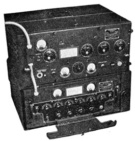
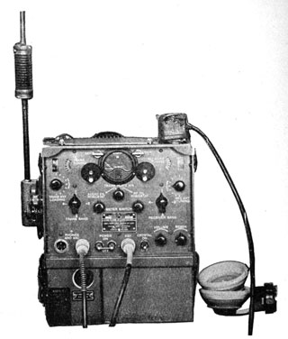
Figure 166.-The TBS transmitter-receiver.
When necessary, the transmitter and receiver may be
separated and used as individual units, but design and
construction make for better operation when the two
sections are installed as a single unit.
285
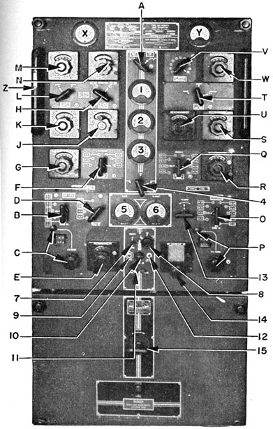
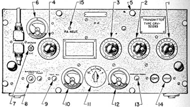
Figure 167.-The TBS transmitter control panel.
TRANSMITTER CONTROL PANEL
1. OSCILLATOR DIAL
Tunes the oscillator plate circuit.
2. 1st DOUBLER DIAL
Tunes the plate circuit of 1st amplifier stage to twice the oscillator frequency.
3. 2nd DOUBLER DIAL
Tunes the plate circuit of the 2nd amplifier stage to twice the frequency of the 1st amplifier stage.
4. POWER AMPLIFIER DIAL
Tunes the power amplifier plate circuit to resonance at the frequency of the 2nd amplifier stage.
5. PILOT LIGHT BULL'S-EYE
Indicates when the motor-generator set is running.
6. R.F.-LINE CURRENT METER
Indicates the r.f. current flowing in the antenna circuit.
7. TUNE-OPERATE SWITCH
Limits the current flowing through the tubes while you are tuning the transmitter. When the set is tuned, this switch is always in the OPERATE position.
8. EMERGENCY STOP-RESET SWITCH
You press the stop button when it is necessary to make a quick shut down of the set.
286
9. TEST SWITCH BUTTON
You press this switch to TEST the transmitter while tuning. Pressing this button applies power to the tubes; releasing the button shuts off the power.
10. PLATE AND GRID CURRENT METER
This meter shows the current flowing in the plate and grid circuits of the transmitter. The current indicated depends upon the setting of the METER SWITCH.
11. METER SWITCH
A five-position switch-O.S.C. IP -1 DOUB. IP-2 DOUB. IP-P.A. IP - and P.A. IG.
12. PERCENT MODULATION METER
Indicates the percent of modulation present with the carrier wave.
13. OVERLOAD RESET BUTTON
This control resets the overload relay after it has been opened by an overload circuit.
14. START-STOP PUSH BUTTON
Used to start and stop the motor-generator.
15. P.A. NEUT. ADJUSTMENT
This adjustment is seldom used by the operator. When this control requires adjustment, call a technician.
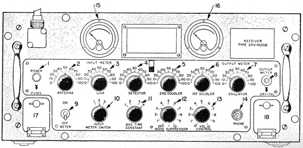
RECEIVER CONTROLS PANEL
1. POWER PILOT LIGHT
Indicates power ON or OFF.
2. ANTENNA KNOB
Tune r.f. input to the receiver.
3. LINK KNOB
Tunes the plate circuit of first r.f. stage.
4. DETECTOR KNOB
TUNES the grid circuit of the first detector stage.
5. 2nd DOUBLER KNOB
Tunes the plate circuit of 2nd doubler stage to twice the frequency of the 1st doubler stage.
6. 1St DOUBLER KNOB
Tunes the plate circuit of 1st doubler stage to twice the frequency of the oscillator stage.
7. OSCILLATOR KNOB
Tunes the plate circuit of the crystal oscillator stage.
8. OUTPUT METER PUSH BUTTON
Pressing this button connects the output meter into the output of the last audio stage.
287
Figure 168.-The TBS receiver control panel.
288
9. POWER, OFF-ON, SWITCH
This switch turns the receiver ON and OFF.
10. INPUT METER SWITCH
This is a three-position switch. It connects the input meter into the cathode circuits to show current flowing in the R.F. AMPLIFIER, 1st DETECTOR, and I.F. AMPLIFIER stages.
11. A.V.C. TIME CONSTANT SWITCH
A four-position switch that sets the speed at which the A.V.C. reacts.
12. NOISE SUPPRESSOR KNOB
Set the level of noise suppression desired. This control also reduces the volume, so that on low signal strength it may be necessary to turn this control off.
13. VOL. CONTROL KNOB
This control sets the level of the desired volume.
14. PHONE JACK
A jack for plugging in a headset.
15. INPUT METER
Indicates the current flowing in the cathode circuits to 1st R.F. AMPLIFIER, 1st DETECTOR, and I.F. stages.
16. OUTPUT METER
This meter indicates the level of audio signal being delivered to the remote or local headsets.
17. FUSE CHAMBER
Access to this chamber is gained through a small door to your left on the panel.
18. CRYSTAL CHAMBER
This chamber contains the crystal for the local oscillator. To change crystal, open access door, remove crystal, and insert the one of the desired frequency.
OPERATION OF THE TBS TRANSMITTER
1. Check the following controls to see they are set in
the indicated positions:
CONTROL
POSITION
START-STOP
STOP
OVERLOAD RESET
PRESS
EMERGENCY
RESET
TUNE-OPERATE
TUNE
METER SWITCH
OSCILLATOR
289
2. Release thumb screws and lift top cover of transmitter. Insert the crystal of the desired frequency
in the crystal holder found in the right-front corner of the chassis. Close and fasten cover.
3. Set all tuning dials in approximately the correct
position as indicated by calibration card. Press
START button.
4. Adjust OSCILLATOR dial until the PLATE and GRID
CURRENT meter drops to minimum. It should indicate about 25 ma. This is just a preliminary
setting of the OSCILLATOR dial.
5. Turn METER SWITCH to 1st DOUBLER position. adjust 1st DOUBLER dial until a minimum indication
is obtained on PLATE and GRID CURRENT meter. It
should be about 35 ma. Make this adjustment
CAREFULLY, because the dip may be slight, and can
be missed easily.
6. Rotate METER SWITCH TO IP -1st DOUBLER position.
Adjust 2nd DOUBLER dial until a minimum indication is obtained on PLATE and GRID CURRENT meter.
It should read about 40 ma.
7. Set METER SWITCH on IP -PA. Adjust POWER AMPLIFIER dial until a minimum indication is obtained on the PLATE and GRID CURRENT meter. It
should read about 70 ma.
8. Place TUNE-OPERATE switch in OPERATE position.
The PLATE and GRID CURRENT meter should show
close to 115 ma. If the meter indicates a current
either above or below this value, call a technician
to make the necessary adjustments.
9. Turn METER SWITCH to IG -PA. Carefully adjust
both DOUBLER dials until a MAXIMUM indication is
obtained on PLATE and GRID CURRENT meter. Next,
detune, the OSCILLATOR slightly by moving the
OSCILLATOR dial a few points TOWARD the HIGH end
of the dial. The PLATE and GRID CURRENT meter
should show about 35 ma.
10. Lock all tuning controls in place. The transmitter
is now ready for operation.
290
To change frequency, turn transmitter off, replace
the crystal with one of the desired frequency, and
repeat the tuning procedure outlined above.
OPERATION OF THE TBS RECEIVER
1. Set the following receiver controls (lower row) in
the indicated positions:
CONTROL
POSITION
INPUT METER SWITCH
3
A.V.C.TIME CONSTANT
1
NOISE SUPPRESSOR
OFF
VOLUME CONTROL
5
2. Turn receiver ON and allow it to warm several
minutes before tuning. With INPUT METER switch
on position three, adjust OSCILLATOR dial slowly
until there is a sharp dip of the INPUT METER
needle. Then move the OSCILLATOR dial SLIGHTLY
to the right of the point where the minimum indication is obtained.
3. Place INPUT METER switch on position numeral.
Adjust the 1st and 2nd DOUBLER dials until a maximum reading is indicated on the INPUT METER.
These dial settings will be close to the settings of
the OSCILLATOR dial.
4. Turn INPUT METER switch to position one, and adjust ANTENNA, LINK, and DETECTOR dials until a
maximum is obtained on OUTPUT METER, or until a
maximum NOISE is heard in the headset or loud
speaker. When frequencies near the lower end of
the band are being used, all the tuning dial settings will be nearly the same. At the high end of
the band, the antenna, link, and detector dials may
vary from the oscillator setting.
5. After tuning is completed, the VOLUME CONTROL is
usually advanced to about 6 or 7 depending on the
strength of the signal and background noises.
6. Turn the NOISE SUPPRESSOR up until as much as
possible of the undesirable background noise is
291
eliminated without cutting off the weakest signal.
With very weak signals, this control may have to
be turned all the way off.
7. Set the A.V.C. TIME CONSTANT to the position indicated for the condition of the operation described.
POSITION 1
High speed telegraphy; telephone communication; when rapid fading is present.
POSITION 2
Medium speed telegraphy; medium rates of fading.
POSITION 3
Slow telegraphic speeds; slow fading.
8. After final adjustments have been completed, close
hinged door and lock in position. If signal
strength falls off, check tuning of receiver. If
tuning is correct, turn up volume control. With
very weak signals, it may be necessary to turn the
noise suppressor down.
9. Remember, the receiver can not be turned on or
off from a remote station. You must do that
manually at the set.
THE TDQ RADIO TRANSMITTING EQUIPMENT
The Navy model, TDQ radio transmitting equipment
is a very high frequency transmitter, 115 to 156 mc.,
specifically designed for voice or M.C.W. communication
with aircraft.
A crystal oscillator containing four interchangeable
crystals determines the specific frequency being used.
The nominal output power of the transmitter is 45
watts. The modulator unit is capable of voice modulating the carrier wave up to 100 percent. On M.C.W.
transmission, modulation up to 85 percent with a 1,000
cycle note is possible. Keying speeds up to 40 words per
minute are permissible.
You may operate the transmitter on a 115 volt or a
230 volt, 50/60 cycle line supply. It may also be used
with a 440 volt, 50/60 cycle supply by using an
292
appropriate step down transformer. When 115 or 230 volt
d.c. supply is to be used, a motor-generator unit with a
magnetic controller must be used.
Three separate units are contained in the TDQ cabinet.
The radio frequency equipment occupies the top portion,
the modulator the middle section, and the power supply
the lower portions of the cabinet.
Operation of the transmitter is possible from either a
local or any one of several remote stations. The TDQ
is intended to be used with the RCK receiver. Both
transmitter and receiver can be controlled from any remote unit.
A single vertical dipole antenna is used with the TDQ,
and is connected to the transmitter by a coaxial
Figure 169.-The TDQ transmitter.
293
transmission line. A special 10 foot length of coaxial cable
is used with all installations that require a transmission
line over 100 feet.
RADIO FREQUENCY SECTION
A. CRYSTAL SWITCH
A four-position switch. Selects the crystal for the frequency desired.
B. OSCILLATOR TUNING
This control tunes the plate circuit of the oscillator to resonance.
C. FIRST TRIPLER TUNING
This control tunes the plate circuit of the first amplifier stage to resonance at the third harmonic of the crystal frequency.
D. PLATE CURRENT SWITCH
A four-position switch-OSCILLATOR, 1st TRIPLER, 2nd TRIPLER, and POWER AMPLIFIER. By using this switch, a single meter, M2, can be used to show the plate current flowing in each of the four indicated circuits.
E. 2nd TRIPLER TUNING
This control tunes the plate circuit of the second amplifier stage to resonance at a frequency equal to three times the frequency of the first amplifier stage.
F. POWER AMPLIFIER TUNING
Adjusting this control tunes the plate circuit of the power amplifier stage to resonance at the frequency of the second amplifier stage.
G. ANTENNA COUPLING
Adjusts the degree of coupling between the power amplifier plate circuit, and the antenna circuit.
M1. POWER AMPLIFIER GRID CURRENT METER
Indicates the grid current flowing in the power amplifier grid circuit.
M2. PLATE CURRENT METER
This meter indicates the current flowing in circuits selected by the plate current switch. (Modulator section.)
M3. DECIBEL METER
Indicates the level of the audio volume delivered by the modulator unit to the transmitter.
J1. MICROPHONE JACK
The jack for the microphone.
J2. HEADSET JACK
The jack for the headset; used when adjusting the transmitter.
H. HEADSET VOLUME
Controls the level of sound being delivered by the modulator to the headset.
294
K. TEST KEY
A three-position SWITCH-LOCK, NEUTRAL, and MOMENTARY. Used in testing the transmitter while you are tuning it.
POWER SUPPLY SECTION
EMERGENCY STOP SWITCH
Used to turn the transmitter off when the situation demands a quick shut-down.
INDICATOR LIGHTS
HEATER indicates when the heater circuit for the crystal heat chamber is energized. CARRIER-this light is on when the microphone, PRESS TO TALK, button is closed. STANDBY - this light indicates when the modulator and r.f. units are energized.
CRYSTAL HEATER SWITCH
Two-position switch, ON and OFF. Applies the energy to the CRYSTAL HEAT CHAMBER.
REMOTE-LOCAL SWITCH
Transfers control of transmitter from a remote unit to you at the transmitter.
START-STOP SWITCH
Turns the set on and off.
TUNE-OPERATE
This switch is used to prevent damage to the transmitter while tuning is in progress.
OVERLOAD RESET
Resets the overload relay after it has opened.
OPERATION OF THE TDQ TRANSMITTER
GENERAL
1. The frequency of the TDQ transmitter is limited to
the frequencies of the harmonics produced by the
four crystals. If other frequencies within the
115-156 mc. range are desired, it is necessary to
interchange crystals. The door above the crystal
selector switch provides access to the crystal
heater chamber.
2. Tuning the r.f. sections consists of resonating the
oscillator plate circuit to the crystal frequency,
the 1st tripler plate circuit to the third harmonic
of the crystal frequency, and the 2nd tripler plate
circuit to the third harmonic produced by the 1st
tripler stage. The power amplifier is tuned to the
frequency of the 2nd tripler stage.
295
STEPS IN TUNING
1. Set the following controls and switches in the indicated positions.
CONTROL
POSITION
EMERGENCY SWITCH
ON
CRYSTAL HEATER
ON
REMOTE-LOCAL
LOCAL
ANTENNA COUPLING, control G ZERO
TEST KEY
NEUTRAL (middle)
TUNE-OPERATE
TUNE
START-STOP
START
2. Set the CRYSTAL SWITCH, control A, in the position
of the desired frequency.
3. Place TEST KEY in LOCK position.
4. Turn PLATE CURRENT switch, control D, to O.S.C.
position.
5. Refer to the calibration card and set O.S.C. TUNING, control B, in the position indicated by the
card. Starting from slightly BELOW the correct
setting, adjust the control until a minimum indication is obtained on the PLATE CURRENT, meter M2.
Then continue to rotate control B toward the HIGH
frequency end of the dial, until the PLATE CURRENT
meter needle has increased about I/2 a scale division.
Lock control B in place.
6. Turn PLATE CURRENT, control D, to "1st T" position,
and quickly adjust 1st TRIPLER TUNING, control C,
until a minimum indication is obtained on the
PLATE CURRENT, meter M2.
7. Turn PLATE CURRENT, control D, to "2nd T," and
quickly adjust 2nd TRIPLER TUNING, control E, until a minimum indication is obtained on the PLATE
CURRENT, meter M2.
8. Turn PLATE CURRENT control D, to "P.A." position,
and quickly adjust P.A. TUNING, control F, until a
minimum indication is obtained on the PLATE current, meter M2.
296
NOTE: For ALL THE FOLLOWING STEPS, place the
TEST KEY in MOMENTARY position, when you are
ACTUALLY ADJUSTING a dial. At all other times
keep it in NEUTRAL position.
9. With the PLATE CURRENT, control D, in P.A. position, place the TUNE-OPERATE switch in OPERATE
position. The plate current should read 100 ma.,
if the r.f. section is properly tuned.
10. Slowly increase the ANTENNA COUPLING, control G,
a few degrees. Readjust control F, until a minimum indication on the PLATE CURRENT, meter M2,
is obtained.
11. Continue to increase ANTENNA COUPLING, control
G, and if necessary readjust P.A. TUNING, control
F, until the PLATE CURRENT meter reads 230 ma.
Do NOT increase plate current beyond 230 ma.
12. Check the P.A. GRID CURRENT, meter M1. It should
indicate 11 to 15 ma. If it is either too high or too
low, call a technician.
13. Press STOP button, and place the REMOTE-LOCAL
switch in REMOTE position.
14. The transmitter can be started or stopped, and
transmit voice or M.C.W. messages from any remote station.
ROUTING OPERATION OF THE TDQ TRANSMITTER
1. Do NOT operate transmitter-that is, press TEST
KEY, TELEGRAPH KEY, or PRESS-TO-TALK microphone button-unless the transmission line is connected to the transmitter.
2. When the transmitter is properly tuned, the TUNE-OPERATE switch will be in OPERATE position, the
TEST KEY in NEUTRAL, and the EMERGENCY switch
ON.
3. Normally the CRYSTAL HEAT switch will be ON at all
times. The HEATER indicator light will be on unless the heater chamber is above 70° C. The thermostat will then open the heater circuit and turn
Out the HEATER indicator light. When the
699198 °-X46-20
297
temperature of the heater chamber falls below 70° C, the
thermostat will close and turn the indicator light
on.
LOCAL TEST FOR OPERATION OF THE MODULATOR
1. Place REMOTE-LOCAL switch in LOCAL position.
Insert microphone plug in MICROPHONE jack, and
headset plug in HEADSET jack.
2. Hold the PRESS-TO-TALK microphone button. The
CARRIER indicator lamp will come on and stay on
as long as the PRESS-TO-TALK button is closed.
3. To hear the incoming signal, provided the TDQ
has the necessary receiving equipment installed
with it, release the PRESS-TO-TALK button. The incoming message will be received instantly. However, if the transmitter is being used for M.C.W.
transmission, a one second delay will occur before
the incoming message can be heard.
4. To control the volume of either the OUTGOING or
INCOMING signal, adjust HEADSET VOLUME, control
H.
THE TBY TRANSMITTER-RECEIVER EQUIPMENTS
The Navy model TBY sets are very high frequency,
portable, transmitter-receivers. They are capable of
two-way communication by either VOICE or M.C.W. telegraphy on any one of 130 different channels within a frequency range of 28 to 80 mc.
These sets have battery power supplies, and are designed for transportation as a knapsack load. They also
can be operated by the man who is carrying them on his
back.
Both transmitter and receiver are housed in a lightweight aluminum cabinet to which the battery power
supply is strapped. The entire assembly is contained in
a canvas carrying case. The case may be partially or
fully removed from the transmitter-receiver as is desired
for the operation of the set.
298
All the operating controls are located on a recessed
front panel. The top of the cabinet is equipped with a
strap handle to facilitate carrying when the unit is out
of its case.
The antenna supports are located on the left side of
the cabinet. The antenna itself is in 10 sections, fitted
together in a "fish-pole" fashion to form a completed unit
nine feet long. The length and diameter of each section
depends on its position in the completed assembly. The
end of each section is color coded to facilitate the proper
assembly of the antenna.
Microphone-headphone assemblies consist of an aircraft anti-noise type microphone and a special lightweight
headphone. The microphone is equipped with a PRESS-TO-TALK switch, which transfers the transmitter-receiver
units from "receive" to "transmit" when pressed. Each
transmitter-receiver unit has two jacks, which permit the
simultaneous use of two microphone-headphone assemblies.
Only one operator may actually control the equipment
at a time. The second operator acts as a monitor during
the operation. Control of the equipment may be transferred from one operator to the other at will.
The key, cord, and plug assembly consists of a specially designed key housing in a small aluminum box. In
addition to the key, this unit contains a SEND-RECEIVER
switch that performs the same function as the press-to-talk switch on the microphone. The whole unit is covered with a rubber cap. This protects the key when the
set is operating in rain or in the presence of spray.
The battery pack is strapped to the underside of the
transmitter-receiver unit. It is equipped with a receptacle which automatically makes the electrical connection
to the transmitter-receiver unit when the battery is installed, thereby facilitating rapid change of batteries.
The complete battery unit is encased in a lightweight
metal container which protects the battery from becoming
defective when set in water or other foreign matter up to
a depth of approximately two inches.
299
Figure 170.-The TBY transmitter-receiver.
THE TBY TRANSMITTER-RECEIVER CONTROLS
TRANS. TUNING CONTROL
This is the vernier control used in the transmitter.
TRANS. BAND SWITCH
A four-position switch that roughly selects the transmitter's frequency.
TRANS. ANT. LOADING CONTROL
This control tunes the transmitter antenna circuit.
RECEIVER TUNING CONTROL
This is the vernier control used in tuning the receiver. The two dials to the right of this knob indicate the setting of the RECEIVER TUNING control.
RECEIVER BAND SWITCH
A four-position switch that roughly selects the receiver's frequency.
300
REC. ANT. TUNING CONTROL
This control tunes the input r.f. stage of the receiver.
LOCK
The two locks on either side of the meter lock the tuning controls in place.
VOLUME CONTROL
Controls receiver volume.
REGEN. CONTROL
Regulates the operation of the detector.
METER
This meter indicates the a.f. filament voltages, r.f. filament voltages, and transmitter plate current, depending on the setting of the METER SWITCH. The "white square" at the middle of the meter face is the only marking used in reading the meter.
METER SWITCH (Directly below meter)
A three position switch that connects the meter into the following circuits: "AUDIO FIL."-Voltage. "TRANS PLATE MA."-Current. "R.F. FIL."-Voltage.
AUDIO FIL. RHEOSTAT
Adjusts the voltage applied to the filaments of the a.f. tubes.
R.F.FIL. RHEOSTAT
Adjusts the voltage applied to the filaments of the r.f. tubes.
PHONE AND MIC. JACKS
Jacks for receiving plugs from handset or chestset cords.
POWER, ON-OFF SWITCH KEY jack
Turns transmitter-receiver ON or OFF. Jack for receiving plug from hand-key cord.
CRYSTAL, ON-OFF SWITCH
This switch connects calibration crystal either IN or OUT of the circuit.
TELEGRAPH KEY (Box on top of cabinet)
This box contains the telegraph key and SEND-RECEIVER switch.
OPERATIONS OF THE TBY TRANSMITTER-RECEIVER
The frequency range of this equipment, as previously
explained, is 28 to 80 megacycles. Throughout this
range, the equipment is calibrated for operation on any
one of 130 channels separated from each other by 400 kc.
The calibration chart on the top cover of the transmitter-receiver unit gives the dial settings and antenna sections
to be used for each of these channels. The channels are
numbered from 1 through 130, with No. 1 channel being
301
the 28 megacycle point and No. 130 the 80 megacycle
point. No reference to frequency is made on the calibration chart as all data are listed according to the channel
number. Operation should therefore be conducted on
channel assignments rather than frequency assignments.
Typical tuning data is included in the chart below.
CHANNEL NUMBER
ANTENNA SECTIONS
TRANSMITTER BAND - DIAL
RECEIVER BAND - DIAL
50
6
3-279
2-998
51
6
3-304
2-1014
52
6
3-328
3-167
If the equipment is to be operated at a fixed location,
the operating site selected should be clear and free from
obstructing objects such as trees, hills, and the like.
When the equipment is to be operated from a man's
back, the tuning procedure for the transmitter differs
slightly from the procedure for a fixed position.
PRELIMINARY
1. Remove the antenna sections from their pocket in
the side of the canvas case, and assemble the NUMBER of sections indicated in the calibration chart for
operation on the desired channel.
2. Remove the combination microphone-headphone
assembly and the key, cord, and plug assembly from
the pocket at the top of the knapsack. Plug them
into the proper receptacles in the front of the panel.
3. Refer to the calibration chart and set the TRANSMITTER BAND and RECEIVER BAND selector switches
and both TRANSMITTER and RECEIVER TUNING CONTROLS to the points indicated for the desired CHANNEL. Turn set ON.
4. Turn METER SWITCH to R.F. FILAMENT voltage, and
adjust R.F. FILAMENT RHEOSTAT until the meter
needle is in the center of the white mark. Next
turn the METER SWITCH to AUDIO FILAMENT voltage
and adjust AUDIO FILAMENT RHEOSTAT until the
meter needle is in the center of the white mark.
302
RECEIVER ADJUSTMENTS
1. Adjust the VOLUME control to approximately its
mid-position. Then advance the REGENERATION
control clockwise from its extreme left hand position until a definite "rushing" or "hissing" sound
is heard in the headphone.
2. Set RECEIVER ANTENNA TUNING control to approximately resonance. This is an estimated setting.
When the control is in the extreme counterclockwise position, it is set for the high frequency end
of the band.
3. Tune in the desired signal by slight readjustment
of the RECEIVER TUNING control, if necessary. correct tuning is indicated by the presence of a minimum of hissing noise.
4. Complete the RECEIVER ANTENNA TUNING until a
minimum amount of hissing noise is heard in the
headset.
5. Make the final adjustment of the REGENERATION
control by setting it at a point just ABOVE the point
where the hissing noise appears.
TRANSMITTER ADJUSTMENTS
1. Turn METER SWITCH to TRANSMITTER PLATE MA.
position. Push press-to-talk button on the microphone, or place the SEND-RECEIVE switch on the
key to SEND position.
2. With the SEND-RECEIVE switch in SEND position, adjust TRANSMITTER ANTENNA LOADING control until
the meter needle is in the center of the white mark
on the meter face. This adjustment should always be made by approaching the proper plate
current value by a clockwise rotation of the antenna control from a ZERO setting.
TELEPHONE OPERATION
1. For telephone operation, after the above adjustments have been made, it is only necessary to press
the press-to-talk button on the microphone and
talk normally into the microphone. The SEND-
303
RECEIVE switch on the key must be in the RECEIVE
position when telephone operation of the transmitter is being used.
TELEGRAPHIC OPERATION
1. For M.C.W. operation of the transmitter, place the SEND-RECEIVE switch in SEND position and operate the key. While M.C.W. operation is being used, a side tone is heard in the headphones making it possible for the operator to hear his own message.
OPERATION WHILE BEING TRANSPORTED ON A MAN'S BACK
1. The operation and tuning of the receiver when the transmitter-receiver unit is being transported on a man's back is exactly the same as it is for operation from a fixed position, since the receiver is not affected by the proximity to the man's body.
2. However, transmitter operation and output frequency are somewhat affected by the nearness of the man's body to the antenna. Therefore, a few slight changes in tuning of the transmitter are necessary.
3. First, tune the transmitter in the normal manner while it is setting in a fixed position. After a normal tuning, ADVANCE the TRANSMITTER ANTENNA LOADING control until the meter needle is about 1/8 inch beyond the white mark.
4. Lift the transmitter to the man's back, and notice the reduction in TRANSMITTER PLATE current. If the needle comes to rest in the center of the white mark, the adjustment is correct. If the needle remains above the white mark, reduce the TRANSMITTER ANTENNA LOADING control until the setting is correct. If the TRANSMITTER PLATE current is less than normal, increase the setting of the TRANSMITTER ANTENNA LOADING.
RECALIBRATION OF TBY TRANSMITTER-RECEIVER
Changing of vacuum tubes, long protracted usage of the set, and even periods of inoperation may cause the
304
frequency of the transmitter-receiver to shift. The amount of change in frequency is often great enough to cause the dial settings to be considerably in error. The crystal oscillator in the set permits you to discover the error and to make the necessary adjustments to compensate for this frequency change.
The crystal in the calibrator circuit is of a 5 me. frequency. The transmitter-receiver frequency is checked on some multiple of this frequency-such as 30, 35, or 40 me.-throughout the frequency band. The settings of the tuning controls for the 10 check points are clearly indicated on the calibration chart.
It is a good practice, to insure being on frequency, to make calibration checks each time before tuning, especially if the set has had continued use, or has been subjected to extensive handling. When making a calibration check, always use two or more check points. Don't depend on a single check to insure accuracy.
RECEIVER CALIBRATION CHECK PROCEDURE
1. Turn the CRYSTAL ON-OFF SWITCH to ON. Set RECEIVER TUNING at the points indicated for the check point selected on the calibration chart. Adjust RECEIVER TUNING control, and RECEIVER ANTENNA TUNING control if necessary, to a point where the hissing sound is minimum. The receiver is tuned to the frequency of the crystal.
2. Turn crystal ON and OFF several times. If the hissing sound appears and disappears each time the crystal is turned off and on, you have the receiver tuned to the correct harmonic of the crystal. If the signal does not appear and disappear, adjust tuning control until it does.
3. When the receiver has been tuned sharply to the crystal frequency, record the dial settings. Check these settings against the calibration chart. If calibration of receiver is correct, these settings will be the same.
4. If the dial readings and indicated chart settings are different, record this difference and use it as a
305
"correction factor" in tuning the receiver.
Example: If the chart indicates the RECEIVER TUNING should be set on 3-983, but the calibration
shows the setting to be 3-987, the chart settings
of the dial are four points TOO LOW. Therefore,
for each setting on the calibration chart, add four
points.
5. If the difference between the actual setting and
chart indications is as much as 20 points, take the
set to a technician for adjustment.
TRANSMITTER CALIBRATION CHECK PROCEDURE
1. Place the set in operation in the normal procedure,
and tune the transmitter to one of the indicated
check points.
2. Turn the CRYSTAL ON-OFF SWITCH to ON. Adjust
the TRANSMITTER TUNING control until a whistling
beat note is heard. Continue to adjust the tuning
control until the low pitched beat note just disappears. If the tuning control is correctly set, the
beat note will reappear when the tuning control
is moved in either direction.
3. While you are making the above adjustment, remain IN ONE POSITION, preferably as far below and
to the right of the antenna as possible.
4. When making calibration checks be sure to keep
TRANSMITTER PLATE MA. normal at all times.
5. If the settings for the controls indicated on the
chart are correct, they should be the same as the
dial settings. If the dial setting and chart indications are different, use this difference as a correction factor the same as with the receiver sections.
Be sure, if the dial settings are lower than the chart
indications, to subtract the differences from the
chart indications.
6. If calibration shows chart settings to be considerably in error, take the set to a technician.