CHAPTER 18 INTRODUCTION TO RECEIVERS OLD FRIENDS AND NEW
Your first contact with radio probably was with a
RECEIVER in your living room at home. Most likely your
knowledge of what made the radio "tick" was limited.
But you could turn it on and twist the knobs to bring in
the ball game or dance band you wanted to hear.
While the home receiver is simple in design, and easy
to tune in comparison to the Navy types, both are essentially the same kind of gear. Each is designed to PICK UP
the electromagnetic wave sent out by a transmitter, and
finally reproduce the sounds in the earphones or loud
speaker.
The comparison of the home and Navy receivers is
much like the relationship of the Piper Cub to the F7F
Tiger Cat. Both planes are designed to fly, only one is
made for slow leisurely flights, and the other is a fighter.
171
JOBS OF A RECEIVER
All receivers have five definite jobs to do-
Pick up signals
Select the desired station
Amplify the weak signals
Demodulate or detect the carrier wave
Reproduce the audio signal
If any of the five are omitted, you do not have a receiver,
but just a collection of wires and vacuum tubes. But
when your gear does these jobs, in the order listed, you
have a radio receiver.
PICKING UP SIGNALS
The RECEIVING of the signal takes place in the ANTENNA.
The antenna may be a whip rising out of the top of your
car, a loop of wire built into a portable radio, or a strand
of wire strung between two masts on your ship.
The antenna and the magnetic field from a transmitter
act together to form an a.c. GENERATOR. Earlier in this
book you learned that if you have together a conductor
and a magnetic field and a relative motion exists between
the two, you have an a.c. generator which will induce a
voltage.
Well, the antenna is the conductor, and the carrier
wave from the transmitter is the magnetic field. Thus,
when a radio wave from a transmitter CUTS ACROSS the
antenna, an emf will be induced in the antenna. The
induced emf is of exactly the same frequency and contains
the identical VARIATIONS that were present when the carrier wave left the transmitter's antenna.
FIELD STRENGTH
The size of the emf induced in an antenna depends upon
the LENGTH of the antenna and the STRENGTH of the carrier wave.
When the carrier wave leaves the transmitter's antenna,
it is strong. As it travels, it gradually loses its strength,
eventually dying out completely. If your ship is near a
172
transmitter, the carrier strength-FIELD STRENGTH-is
great. But a thousand miles away, the same carrier
wave will be very weak.
In the last chapter of this manual you will learn that
factors other than distance influence the FIELD STRENGTH
of a carrier wave, but for the time being you can consider
distance as the only factor.
A carrier wave's FIELD STRENGTH is measured by the
emf, in microvolts, that is induced in an antenna one
meter (39.4 inches) long. For example-transmitter A
induces an emf of 100 microvolts in an antenna one meter
long. Transmitter B, which is nearer, induces an emf
of 1,000 microvolts in the same antenna. By comparison,
the field strength of the transmitter B is ten times that of
transmitter A. Thus, if the field strength of a certain
transmitter is 100 microvolts per meter, an antenna three
meters long will have an induced emf of 300 microvolts.
The minimum field strength necessary to produce good
reception depends upon the kind of receiver and the
amount of noise interference in the neighborhood of your
receiver.
RECEIVER SENSITIVITY
The sensitivity of a receiver is a measure of HOW WELL
it can amplify weak signals. The average home radio
can amplify the signals only a few hundred times, but
the receivers used aboard your ship are capable of amplifying a signal millions of times. Because of this great
amplification, a communications receiver can operate on
weaker signals than a home receiver.
A receiver that STARTS with a SMALL signal and FINISHES with a LARGE signal has HIGH SENSITIVITY.
It you are in an area of strong local interference, you
need strong signals to produce good reception. When the
local interference has a FIELD STRENGTH of 100 my. per
meter, you will need a signal strength of 500 to 1,000 my.
per meter to drown-out the noise. But the same receiver,
free from local interference, may give good reception
when signal strength is less than 10 mv. per meter.
173
Although it is difficult to state the exact minimum field
strength that is needed to operate a receiver satisfactorily,
many communication receivers under ideal conditions are
able to operate on a signal strength that is considerably
less than 1 mv. per meter.
GETTING YOUR STATION
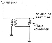
You TUNE your receiver by adjusting the variable condensers until the RESONANT FREQUENCY of tank circuits
in the receiver is the same as the FREQUENCY of the station
you wish to hear. Figure 123 is a TUNING CIRCUIT,
Figure 123.-Tuning circuit.
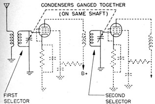
Usually two or more stages of tuning are needed to separate the stations that are transmitting on neighboring
frequencies.
As shown in figure 124, the condensers are mounted
(ganged) on the same shaft so that both are tuned with
one twist of the knob. The greater the number of circuits used, the sharper will be the tuning. A receiver
that tunes SHARP is said to be SELECTIVE.
HOW SELECTIVE
Some types of communication receivers may be more
selective receivers than others. A receiver used for
174
Figure 124.-Two-stage tuning.
C.W. code can be more selective than a voice receiver.
A communications voice receiver is designed to tune
more sharply than a common broadcast receiver that
you'll use to pick up Dinah Shore and Benny Goodman.
In general, communication receivers do not make good
instruments for receiving music. The reason why is
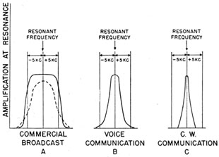
illustrated in figure 125.
Figure 125.-Band widths of various types of receivers.
175
Carrier waves from commercial broadcast stations
contain SIDE-BAND FREQUENCIES which extend five kc on
either side of the RESONANT FREQUENCY. That means, if
a station is transmitting on a frequency of 1,140 kc, the
complete carrier wave will contain frequencies from
1,135 to 1,145 kc. If a receiver tunes too sharply, the
higher side band frequencies will be lost. For this
reason, broadcast receivers can furnish high-fidelity reception only if they tune broad enough to include BOTH
SIDE BANDS.
Figure 125 shows the best TUNING CURVE for a broadcast receiver The top is broad and flat and the sides
are steep. Most cheap broadcast receivers have tuning
curves as shown by the broken lines. This design permits a lot of station interference resulting in low fidelity
The band width necessary for a satisfactory VOICE
COMMUNICATION may be narrower than for the broadcast bands. Clear and intelligible messages can be obtained on bands that extend only one kc on either side of
the resonant frequency. The voice may sound unnatural,
but it will get through.
Transmissions for c.w. code messages contain no side-bands-just the r.f wave alone. Therefore c.w, receivers can tune very sharply.
VERNIERS AND SPREADERS
The first time you try to tune a Navy receiver you
probably won't bring in a thing. You are accustomed to
using broad-tuning home receivers, and you'll have to
develop the touch-get that old safe-cracker's feel in
your finger-tips-before you'll be able to tune a shipboard receiver. A hair's breadth movement of the dial
can take you past a station without even hearing a good
"bloomp."
And that brings up the tuning aids you'll find on communications receivers-VERNIERS, BAND-SPREADERS, TUNING EYES, AND TUNING METERS-all put on to help you
find the station you want.
176
The VERNIER DIAL is the most common device. Many
vernier dials have two or even three speeds. You use
the COARSE adjustment to bring in the station, then the
MEDIUM and FINE speeds to polish up the tuning.
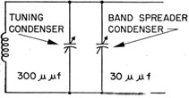
Other receivers use a system of BAND-SPREADING. You
put a small variable condenser having about one-tenth
the capacity of the tuning condenser in parallel with the
tuning condenser, as shown in figure 126.
Figure 126.-Band spreaders.
When using BAND-SPREADING, you adjust the large tuning condenser to approximately the correct capacity and
then complete the tuning by adjusting the small variable
condenser. The small capacity of the band-spreader
condenser permits wide movement of the dial and gives
the appearance of spreading the station channel wide on
the dial.
Some receivers have a SWITCHING ARRANGEMENT
which permits preliminary tuning to be broad, and the
final adjustment to be sharp.
Many receivers have TUNING EYES or TUNING METERS
to indicate the presence of automatic volume control
(A.V.C.) voltage, and this voltage appears only when a
station is tuned in. You'll hear more about this later.
R. F. AMPLIFICATION
Look back at figure 124. In addition to the tuning
circuits, you have TWO STAGES OF R.F. AMPLIFICATION.
The amplifier circuits are similar to those you learned
back in chapter 15. The tubes are PENTODES and the
stages are COUPLED together by r.f. transformers.
177
THE DETECTOR STAGE
The DETECTOR follows the last r.f. amplifier stage. It
is in this stage that the a.f. wave is separated from the
r.f. component of the carrier wave The r.f. component
is cast aside and the a.f. portion is sent on to the audio
stage for more amplification.
AUDIO FREQUENCY AMPLIFIERS
Most receivers have TWO a.f. amplifier stages. The
first is a voltage amplifier used to drive the output
POWER AMPLIFIER stage. It is in the POWER AMPLIFIER
that the power of the a.f. wave is stepped up to a strength
sufficient to operate the LOUD SPEAKER or EARPHONES.
RECEIVER CIRCUITS
There are a great number of receiver circuits being
used to do the five jobs listed back on page 172. But the
majority of Navy receivers fall into two classes-the
TUNED RADIO FREQUENCY, and the SUPERHETERODYNE.
Both receivers operate by having an emf induced in the
antenna and by transforming this signal to a sound from
the loudspeaker. But the WAY the two circuits perform
their duties between the antenna and loudspeaker is quite
different.
TUNED RADIO FREQUENCY RECEIVER
The TUNED RADIO FREQUENCY receiver, T.R.F., is simpler in design than the superheterodyne.
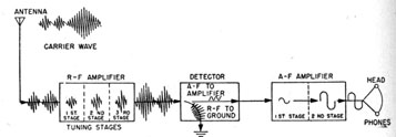
Figure 127.-Block diagram of a T.R.F. receiver.
178
The block diagram in figure 127 divides the T.R.F.
receiver into its three major parts. The first part is the
r.f. sections, containing one, two, or even three, stages
of r.f. amplification. It is in these stages that the tuning
of the receiver takes place.
Following the r.f. amplifiers is the DETECTOR, in which
the a.f. component is separated from the r.f. portions of
the carrier wave.
The a.f. wave is sent on to the third part-the audio
frequency amplifier-where further amplification takes
place. The last step is completed when the audio signal
finally appears in the earphones (or loudspeaker) as a
sound.
Look back again at figure 127 and trace the progress
of the carrier wave through the receiver. In the beginning
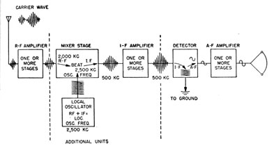
Figure 128.-Block diagram of a superheterodyne.
the carrier wave induces a FEEBLE emf in the antenna. Each stage amplifies this feeble voltage until it
enters the detector with considerable strength. In the
detector the r.f. and a.f. components are separated. The
r.f. portion is carried to the ground, and the a.f. part
goes to the a.f. amplifier stage.
179
THE SUPERHETERODYNE RECEIVER
The SUPERHETERODYNE receiver contains all the major
units of the T.R.F.-with THREE ADDITIONS. In figure
128 the r.f. amplifier and detector of the T.R.F. have
been cut apart, and the three additional units (MIXER,
LOCAL OSCILLATOR, and INTERMEDIATE FREQUENCY AMPLIFIER) are inserted.
The operation of the r.f. detector, and a.f. stages is
exactly the same as in the R.T.F. receiver, but new units
change the basic operation of the circuit completely.
The object of placing the additional units in the circuit
is to produce a SINGLE CONSTANT RADIO FREQUENCY.
This constant frequency is called the INTERMEDIATE FREQUENCY. Here is the story-
The carrier wave from the r.f. amplifier is FED into the
vacuum tube of the MIXER STAGE. A second higher r.f.
is produced by a LOCAL OSCILLATOR, and fed into the
SAME vacuum tube. In this tube, the r.f. signal BEATS
against the local oscillator signal and produces a THIRD
frequency, the INTERMEDIATE FREQUENCY.
How does all this come about? The word BEAT is the
clue to the answer.
WHAT ARE BEATS?
Did you ever hear two persons playing musical instruments that were slightly out of tune with each other?
Certainly you have. DISCORDS were produced, and those
discords were BEAT NOTES.
Beat notes are produced when two wave motions of
slightly different frequency strike, or beat, against each
other. For example, suppose two notes, one of 1,200
cycles and the other of 1,500 cycles, BEAT against each
other. Part of the time the two will work against each
other, and part of the time they will work together. This
produces TWO NEW NOTES, in addition to the two original
notes. One equal to the sum of the original frequencies-
1,500 + 1,200 = 2,700 cycles
180
The other is equal to the difference between the original
frequencies-
1,500 - 1,200 = 300 cycles
The 2,700- and 300-cycle notes are BEAT NOTES. In the
same way, beat notes always appear when two unequal
frequencies are mixed together. One of the new pates is
equal to the SUM of the two frequencies and the other is
equal to their DIFFERENCE.
HOW THE INTERMEDIATE FREQUENCY IS PRODUCED
Now go back to the superheterodyne, in which you wish
to produce a SINGLE CONSTANT INTERMEDIATE FREQUENCY.
Suppose the I.F. desired is 500 kc. You could produce
it by mixing ANY two frequencies whose SUM or DIFFERENCE is equal to 500 kc. But in practice you would use
only the DIFFERENCE to produce the WANTED frequency.
Remember, ANY two frequencies whose DIFFERENCE
equals 500 kc. will do. Thus if the incoming CARRIER
WAVE is 2,200 kc., the OSCILLATOR frequency must be
2,700 kc. to produce an I.F. of 500 kc. Or you may use
any number of other combinations such as-
Carrier
Oscillator
Difference
Frequency
Frequency
(I.F.)
2,400 kc.
2,900 kc.
500
3,150 kcs.
3,650 kc.
500
7,230 kcs.
7,730 kc.
500
And you could go on and fill the rest of this manual with
other combinations whose differences are equal to 500 kc.
Notice the oscillator frequency. It is 500 kc. MORE
than the incoming CARRIER WAVE.
2,900 - 2,400 = 500
3,650 - 3,150 = 500
Or turn it around-the oscillator frequency is equal to
the carrier frequency PLUS the intermediate frequency-
2,400 + 500 = 2,900
3,150 + 500 = 3,650
To sum it up-in a superheterodyne receiver the oscillator generates a frequency that is always the I.F.
181
HIGHER than the incoming carrier wave. The DIFFERENCE
between carrier and oscillator frequencies will always be the intermediate frequency.
The condenser that tunes the oscillator is connected, or
ganged, to the SAME shaft that tunes the r.f. sections of
the radio. And by turning a single knob, the oscillator
is automatically tuned to the I.F. HIGHER than the incoming r.f. carrier wave.
Since the I.F. signal is a COMBINATION of the local oscillator and the carrier wave signals, it will be MODULATED and have the same characteristics as the carrier,
only at a lower frequency.
Look back again at figure 128. The output from the
mixer stage is sent into the I.F AMPLIFIER, where the
voltage of the I.F. is still further strengthened. And
the output of the I.F. amplifier is sent into a detector
where the r.f. and a.f. components are separated, just as
they are in the T.R.F. receiver.
Sometimes you will hear the MIXER stage called the
FIRST DETECTOR and the other detector stage the SECOND
DETECTOR. Don't let it trouble you. The term FIRST
DETECTOR comes from the fact that the production of beat
notes is sometimes called HETERODYNE DETECTION.
WHY THE EXTRA PARTS
You may wonder why all the extra parts are added to
a T.R.F. receiver to form a SUPERHETERODYNE when the
T.R.F. does a good job. That is a sensible question.
The answer is-the superheterodyne does a BETTER job.
Increased SENSITIVITY and SELECTIVITY make the superheterodyne a much better receiver for the reception of
weak signals. That is reason enough.
BAND SWITCHING
Practically all Navy receivers are made to tune over
several BANDS of frequencies. The RBB/RBC receivers
have four bands; the RAK has six and the RAL has nine.
To change from one band to another, it is only necessary
to rotate a switch to the band you wish to use.
182
When you are operating near the TOP of one band,
you may find that you also receive the same station near
the BOTTOM Of the, upper band. EXPERIENCE will tell you
which setting gives the best results with your particular
set.
Some receivers, especially the T.R.F. types, have TRIMMER controls that are adjusted each time you change
frequency bands. This is done by opening the TUNING
condensers to their widest mesh at the high end of the
frequency band, and then adjusting the trimmer controls
until the noise level is maximum.
This control is necessary because, in spite of the greatest care in manufacturing, coils have slight differences in
their windings. This causes variations in the resonant
frequencies of the several tuning stages. The trimmer
controls correct these variations.
RECEIVER CALIBRATION
The CALIBRATION of a receiver is only the RECORD of the
dial settings indicating where you can find a station of a
certain frequency. As an example, if you lived near
Chicago, you knew that WGN could be picked up by
setting the dial at 720. Maybe your receiver was a little
out Of adjustment and you got the station by setting the
dial at 710 or 730. You didn't write these numbers down,
you just remembered them. That is a rough example of
calibration.
Most Navy receivers have several dials to be set for
each station you receive. To save time wasted in hunting
all over the band, and in trying to remember the proper
settings, you will RECORD the positions of ALL the dials
for EACH STATION you listen to. The resulting chart is
the calibration of your receiver.
To calibrate a receiver properly you must very carefully check the settings of the dial against known frequencies. Then, when you are instructed to listen to a
station transmitting on 2,120 kc, you can turn to the
chart and find the exact setting for each dial.
183
VOLUME CONTROLS
In addition to the TUNING knobs, all Navy receivers
have several other dials and controls to help you in
operating the set.
The VOLUME CONTROL is the most familiar. With it
you increase or decrease the volume of sound to the desired level. Your receiver at home has one of these
controls.
The r.f. GAIN CONTROL, sometimes called sensitivity
control, is closely related to the volume control. You
can raise and lower the output sound level with it, but
that is not its prime purpose. This gain control is
usually located in the first r.f amplifier stages. When a
very weak station is being received, this control is turned
all the way up; but if you are tuned to a strong station, the
control is turned DOWN to prevent OVERLOADING the r.f.
tubes. This is necessary since overloading causes SERIOUS DISTORTION in the signal.
AUTOMATIC VOLUME CONTROLS
The AUTOMATIC VOLUME CONTROL, AVC-sometimes
called AUTOMATIC SENSITIVITY CONTROL, ASC-serves to
keep the output volume at a constant level. This saves
you the job of continually turning the manual volume
control up and down each time the stations being received FADE and. REAPPEAR in strength.
Most AVC systems have two controls, an OFF-ON switch,
and an AVC LEVEL regulator. It is the usual practice
to turn the AVC off while tuning the receiver. When
the receiver has been tuned, the switch is turned ON, and
the LEVEL is adjusted for the desired operation.
The AVC system in most Navy receivers is too rapid
and pronounced to permit its use with voice reception.
So the AVC usually will be OFF when you are receiving
a voice message.
NOISE SUPPRESSORS AND OUTPUT LIMITERS
The high sensitivity of all communication receivers
causes them to pick up a lot of local interfering noise
184
and natural static. This is especially objectionable when
receiving code messages, because a crash of static may
cause you to miss several letters in a code group.
The NOISE SUPPRESSOR works much the same as a TONE
CONTROL in a home receiver. When this control is turned
for DEEP or BASS reception, much of the noise is FILTERED
OFF and is not permitted to reach the earphones. But
the noise suppressor also reduces the volume. So on
very weak, signals, it may be necessary to turn the switch
that cuts it out of the circuit.
The OUTPUT LIMITER prevents sudden crashes of static
from bursting your ear drums. There are several ways
this can be done, but all work as a safety POP-OFF valve.
When the output volume of sound reaches a certain level,
the output limiter goes into action and prevents the sound
from rising any higher.
Some receivers have circuits called SILENCERS, designed to keep the receiver silent when no signal is being
received. This is very useful when you are standing by
to receive a message.
Most output limiters and silencers have OFF-ON
switches, and an OUTPUT LEVEL adjustment. The specific
name used for these controls depends upon the particular
make of the set.
OUTPUT METERS
Many receivers use a meter to show the level of SOUND
OUTPUT. It is also useful as an aid in tuning the receiver,
especially where you are SEARCHING for a station that
is not on the calibration chart.
These meters are made to indicate the presence of a
station even when the sound is considerably below the
minimum level your ears can hear. Once the presence
of a station is indicated by the meter, the volume can be
brought up to audible level by turning up the sensitivity
control.
Most output meters are calibrated in DECIBELS. A decibel is the SMALLEST difference in sound your ear can
699198°-46-13
185
detect, and ZERO decibels is the LOWEST level of sound your
ear can hear. For most references, ZERO decibels is
numerically equal to 6 milliwatts (0.006 watts).
The output meter is used by the Electronic Technician's
Mate when he is aligning, or tuning up, your receiver.
With this meter he will be able to tell whether a station
with a certain signal strength can be heard.
OTHER METERS
Some receivers have two other meters-one to indicate
the FILAMENT VOLTAGE, and the other the PLATE VOLTAGE.
A control accompanies each meter, so that if the voltages
are incorrect, you can correct them.
BEAT FREQUENCY OSCILLATOR
The BEAT FREQUENCY OSCILLATOR, B.F.O., is a part of
every communication receiver designed to receive C.W.
messages. When the receiver is being used to receive
I.C.W., modulated C.W., or voice messages, the B.F.O. is
always turned OFF.
With each B.F.O. is a TUNING control, sometimes
marked A.F. TUNING. With this control, you adjust the
PITCH of the audio note to the desired frequency.
The B.F.O. is usually connected to the detector tube in
the T.R.F. receiver and to the second detector in the
superheterodyne.
The frequency of the B.F.O. is about 1,000 cycles less
than the incoming carrier wave with the T.R.F., and
1,000 cycles less than the I.F. in the superheterodyne
receiver. For example, if the carrier frequency being
received by a T.R.F. is 4,720 kc., the B.F.O. will be tuned
to approximately 4,719 kc., so the BEAT note produced
will be-
4,720 - 4,719 = 1 kc. (1,000 cycles)
In a superheterodyne, if the I.F. is 500 kc., the B.F.O.
will be tuned to about 499 kc. This also will produce a
beat note of 1,000 cycles. By adjusting the B.F.O. you
can raise or lower the pitch of the beat note to a frequency
slightly above or below the 1,000 cycle note.
186
A four position switch usually accompanies the B.F.O.
tuning control. It is usually marked B.F.O.-ON, MOD-C.W., I.C.W., or VOICE. When using the receiver you will
turn this control to the position that matches the type of
message being received.
A CRYSTAL FILTER control is used in connection with
many B.F.O.'s. Its purpose is to prevent interfering
noises and notes from blotting out the tone of the C.W.
signal. The filter has two controls, an OFF-ON switch,
and a REJECTION control. Sometimes, the OFF position
of the switch is marked BROAD, and the ON position, SHARP.
The REJECTION CONTROL is adjusted for beat reception
each time the filter is turned on.
Don't be surprised to find controls other than those
just described. Almost every receiver has some special
knob all its own. You can find all this specialized information in the manufacturer's instruction books.