The subject of this chapter has two names-CONDENSER
and CAPACITOR-and both names are OK. A lot of hot
arguments go on over which is the correct name. Some
men argue, and probably rightly so, that the name CONDENSER is wrong, since NOTHING is CONDENSED. These
men prefer the term CAPACITOR, since the gadget has the
CAPACITY to hold a charge. But actually, a charged condenser does not contain ONE MORE ELECTRON than when
discharged.
What it boils down to is this-take your pick. You
can use either term you choose. However, this book uses
CONDENSER, because this term is older and probably more
widely used.
Many natural condensers are formed. A cloud moving
above the surface of the earth becomes charged, and
possesses characteristics of a condenser. A bolt of lightning is simply the DISCHARGE of one of these natural
condensers.
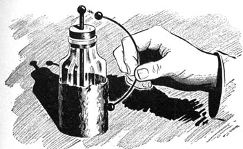
Your body, when you are near an improperly shielded
or poorly constructed radio receiver, can also form a
103
condenser. You certainly have seen receivers with which
it was necessary to hold your hand in one spot in order
to get the program. With such receivers, your hand is as
much a part of the circuit as a vacuum tube or a resistor.
Watch your step when handling condensers. They
are interesting little gadgets that can do you wrong if you
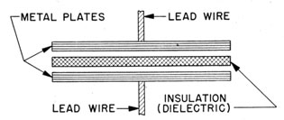
Figure 87.-Simple condenser.
get hold of a "hot" one. Small condensers are not too
dangerous, but big ones are capable of killing a person.
WHAT IT'S LIKE
In physical structure the condenser is one of the simplest electrical devices used in radio circuits. Basically
it is TWO METAL PLATES separated by an INSULATOR.
Notice, in figure 87, the insulation is called the DIELECTRIC.
It may be MICA, GLASS, WAXED PAPER, CERTAIN CHEMICALS
IN SOLUTION, or AIR.
The physical appearances of condensers are as varied
as 5th Avenue hats on Easter morning. Some are small
and simple in design, others are large and complex.
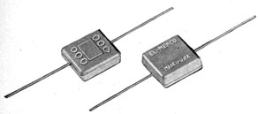
The MICA CONDENSERS, figure 88, are the smallest.
They have two metal plates separated by a sheet of mica.
The whole unit is enclosed in a plastic case. Many of
these mica condensers are about the size of postage
stamps.
The TUBULAR CONDENSER, figure 89, is next in size to
the mica condenser. Most are from 1½ to 2½ inches
104
Figure 88-Mica condenser.
long and 3/8 to 3/4 inch in diameter. They are formed by
making rolls of two sheets of tin foil separated by waxed
paper. Because of the paper dielectric, these condensers
are often called PAPER CONDENSERS.
The edges of the individual sheets of tin foil are soldered together to provide the dove-tailed appearance of
the illustration. If the two pieces of foil touch, the condenser is shorted, and is no good.
Figure 89.-Tubular or paper condensers.
699198°-46-8
105
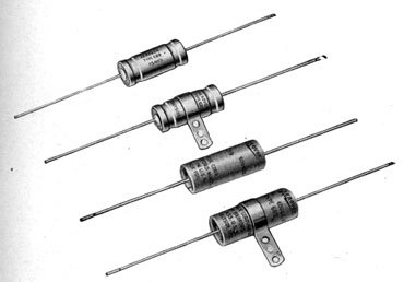
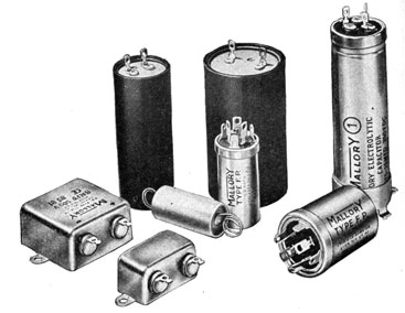
The ELECTROLYTIC CONDENSERS are usually larger than
tubular condensers. In figure 90, the one to the right
with a large numeral 1 is about 6 inches long and 1½
inches in diameter. The others are of sizes in proportion to this one.
The plates of electrolytic condensers are tin foil, or a
slightly thicker sheet metal. The dielectric is a porous
paper soaked in CHEMICALS. The metal plate and dielectric are rolled together just as they are in tubular
condensers.
All electrolytic condensers have a POSITIVE and a NEGATIVE terminal. When connecting one of these into a circuit, you must be very careful to connect the + on the
condenser to the POSITIVE potential in your radio. Otherwise the condenser is liable to blow up or burn out.
Figure 90.-Electrolytic condensers.
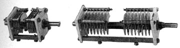
The VARIABLE CONDENSER is the gadget you turn when
you TUNE your radio. There are a great many different
sizes and shapes of these, but all present an appearance
similar to those in figure 91. One set of plates is FIXED
and the other MOVABLE. It will not be unusual to find
106
Figure 91.-Variable condenser.
two, three, and sometimes four sets of condensers
GANGED together on a single shaft.
When you start digging into the chassis of a radio,
don't be surprised to find condensers other than those
described here, because someone is always dreaming up a
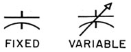
new design. The schematic symbols for FIXED and
VARIABLE CONDENSERS appear in figure 92.
Figure 92.-Symbols for fixed and variable condensers.
WHAT IT DOES
The condenser is the only known device that can store
ENERGY as ELECTRICITY. In a battery, it is stored as chemical energy. In a coil, energy is stored in the magnetic
field. But in a condenser, it is stored as DISPLACED
ELECTRONS.
In the first chapter of this book, you were told that
metals have a great many FREE ELECTRONS, and that when
the proper force is applied these electrons may be pulled
away from one metal and added to another.
107
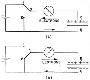
In figure 93, the two plates of the condenser are designated
as P1 and P2. In drawing A, the switch S is turned
to position 1. The emf of the battery will pull FREE electrons off P1 and place them on P2. This CHARGES THE
Figure 93.-Condenser action.
CONDENSER. Since electrons have been removed from P1
and added to P2, P1 will be POSITIVE and P2 NEGATIVE.
When switch S is moved to position 2, the condenser
will DISCHARGE. Excess electrons will leave P2 and run
back onto P1, until an EQUAL number of electrons are on
each plate.
Each time the switch is turned to position 1, the condenser will charge, and when the switch is turned to
position 2, it will discharge. This CHARGING and discharging is known as CONDENSER ACTION.
A condenser is FULLY CHARGED when the potential across
the plates is EQUAL to the APPLIED emf. And it is completely discharged when the potential across the plates
is ZERO.
A condenser does not become charged the instant The
emf is applied. The amount of time required for a condenser
108
to charge or discharge is determined by two
factors-the RESISTANCE of the circuit, and the SIZE of
the condenser.
SIZE OF THE CONDENSER
The SIZE of a condenser does not refer to its physical
dimensions, but rather to the number of electrons that
can be moved with one volt of applied emf.
The size of a condenser is more properly known as its
CAPACITY. The unit of CAPACITY is the FARAD-the ELECTRICAL EQUIVALENT of ONE VOLT displacing a COULOMB of
electrons.
A condenser with a capacity of one farad would be
larger than a 5" 38 gun mount. The usual condenser
capacity is in millionths of a farad-a MICROFARAD. Or
still smaller, a MILLIONTH of a MILLIONTH-a MICRO-MICROFARAD. The abbreviation of microfarad is mfd or
μfd, and of micro-microfarad it is mmfd or μμfd.
Mica condensers have capacities ranging from about 10
mmfd to 1,000 mmfd. Paper condensers range from
0.0001 mfd to five mfd, and electrolytic condensers from
about one mfd to 50 or 60 mfd.
Many special condensers with capacities greater or
smaller than those listed have been made, but the majority used in your radios are within the indicated ranges.
VARIABLE CONDENSERS also have a wide range of capacities, of course. AT FULL MESH-all the way closed-they vary from 400 mmfd down to about 10 or 20 mmfd.
A CONDENSER BLOCKS D. C. BUT CONDUCTS A. C.
One of the most used features of a condenser is its
ability to BLOCK the flow of d.c., and to CONDUCT a.c.
When a condenser is connected into a d.c. circuit, it will
quickly become charged. When fully charged, the flow
of electrons is stopped, and the condenser acts as an OPEN
CIRCUIT.
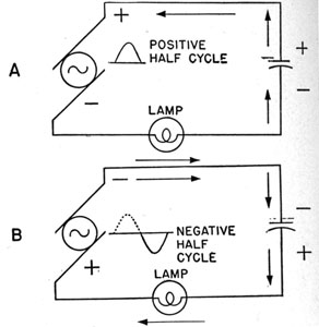
A condenser connected into an a.c. circuit acts quite
differently. In figure 94, a condenser is connected in
series with a lamp and a generator. During the positive
109
Figure 94.-A condenser conducts a.c.
half-cycle, electrons leave the upper plate, flow through
the generator and lamp, and onto the lower plate of the
condenser. But, during the negative half-cycle the electrons reverse their direction. Now they flow out of the
lower plate, through the lamp and generator, and onto
the top plate of the condenser.
Each time the cycle reverses, the electrons leave one
side of the condenser and enter the other. In this way
electrons continue to flow through the lamp as long as the
generator is running.
Remember that electrons do not go through the condenser. They merely run out of one side and in at the
other.
A CONDENSER HAS REACTANCE
A condenser has an opposition to the flow of current,
and like coils, the opposition is called REACTANCE-or
more specifically, CAPACITIVE REACTANCE, XC.
110
The amount of capacitive reactance is determined by
the CAPACITY of the condenser and the FREQUENCY of applied emf. With a condenser, the LARGER the CAPACITY and
higher the FREQUENCY the LOWER the XC. The formula
for finding the capacitive reactance of condenser is-
XC = 1 / 2πfC
Where XC is the capacitive reactance in ohms, f is the frequency in cycles, C is the capacity of the condenser in farads. 2π is 2 X 3.14 or 6.28.
Since both f and C are in the denominator, the LARGER
they become the smaller XC will be.
A condenser with a capacity of one mfd carrying an a.c.
of 100 cycles will have an XC of-
XC = 1 / (2 x 3.14 x 100 x .000001) XC = 1600 ohms approximately
But, at a frequency of 1,000,000 cycles, it will have an
XC of only-
XC = 1/ (2 x 3.14 X 1,000,000 X .000001) XC = .16 ohms approximately
If you DOUBLE the capacity of a condenser you cut the
capacitive reactance in HALF. Increasing the size of condenser by 10 reduces its XC, (at any specific frequency) to
1/10 of its former value.
Remember this, as the FREQUENCY of the current and
CAPACITY of the condenser INCREASE, the CAPACITIVE
REACTANCE of the condenser DECREASES.
111
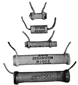
A NEW CONDENSER
Recently, a new style of condenser has been used in
many of the high frequency circuits of receivers. The
first glance at this newcomer would make you think it is a
resistor, but careful examination would reveal the error
of your guess. Look carefully when you see a device that
looks like figure 95. It may be a new style condenser.
Figure 95.-Ceramic condensers.
These condensers are made of silver coated on a ceramic
material. They are used to compensate for changes in
capacity with temperature variations.