1. PURPOSE: General communication for small ships.
2. FREQUENCY RANGES:
(a) IF, 300 to 1,500 kc.
(b) HF, 1,500 to 18,100 kc.
3. EMISSION:
(a) A-1 or CW, up to 100 words per minute.
(b) A-2 or MCW, up to 100 words per minute.
(c) A-3 or VOICE.
4. POWER OUTPUTS:
(a) 125 watts CW.
(b) 35 watts MCW.
(c) 30 watts VOICE.
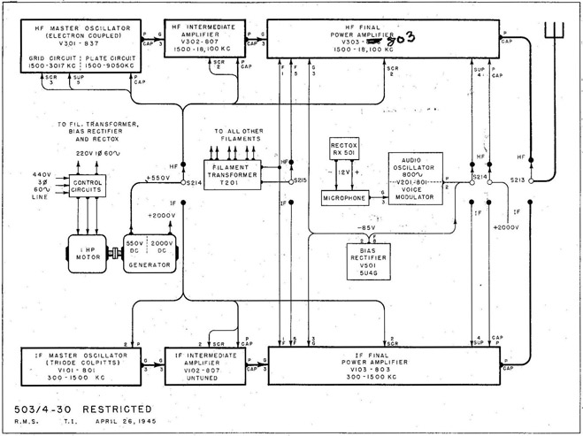
5. HF-IF TRANSFER SWITCH (S-213, S-214 and S-215):
(a) S-213 transfers the antenna to either the HF or the IF transmitter.
(b) S-214 transfers the DC plate and bias voltages, and the output of the audio oscillator - voice modulator (V-201) to either transmitter.
(c) S-215 transfers the PA filament supply to either transmitter.
36
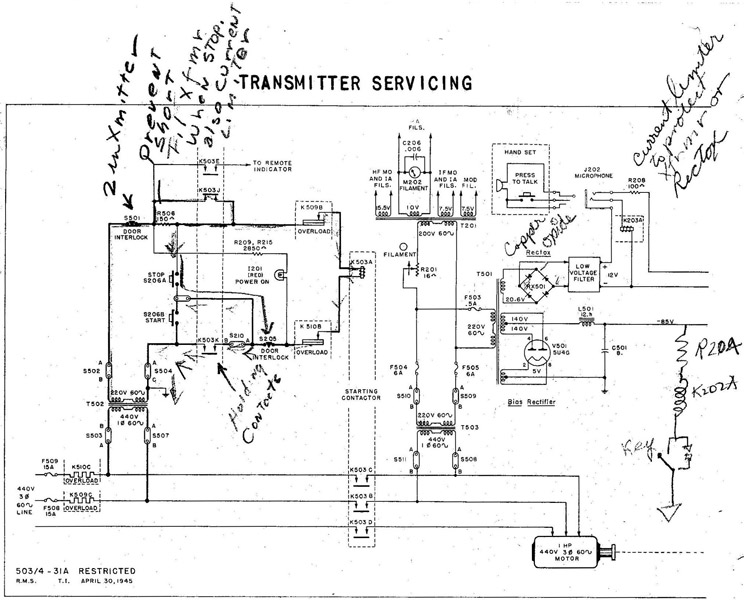
Fig. 31 TDE-2 Transmitter (AC Model) Control and Power Circuits.
1. PURPOSE: To simplify starting and stopping the transmitter and to convert the line supply to the types of power required by the transmitter..
2. GENERAL CIRCUIT CONDITIONS:
(a) Transmitter control circuits connected for Navy 6-wire control unit.
(b) Control circuit power transformer (T-502) is energized from one phase of the 440-volt three phase main line.
(c) Three main power conversion units are:
(1) Motor generator with 550-volt and 2,000-volt DC outputs.
(2) Bias rectifier (V-501) with 85-volt DC output.
(3) Rectox unit with 12-volt DC output for microphone.
3. STARTING THE TRANSMITTER:
(a) Press START switch (S-206B) to energize starting contactor (K-503).
(1) Starting contacts (K-503B, C and D) connect the line to the motor and to the power transformer (T-503). The filament transformer (T-201) and the rectifier transformer (T-501) both are energized from the secondary of T-503.
(3) Normally closed contacts (K-503J) open to leave R-506 in series with starting contactor coil (K-503A).
37
TDE-2 TRANSMITTER
4. ADJUSTING THE TRANSMITTER SUPPLY VOLTAGES:
(a) Filament voltages for all tubes should be correct when the FILAMENT control (R-201) is adjusted for 10 volts on FILAMENT meter (M-202).
(b) All plate voltages should be correct when PLATE control (R-501) is adjusted for 2.0 kilovolts on PLATE meter (M-205).
5. PERSONNEL PROTECTION: Door interlocks (S-501 and S-205) in series with K-503A.
6. OVERLOAD PROTECTION:
(a) Fuses in the +2,000-volt and +550-volt leads, in the primary circuits of rectifier transformer (T-501) and filament transformer (T-201). and in two of the main line leads.
(b) Thermal overload relays (K-509 and K-510) with heaters in two of the main line leads. Prolonged overload that fails to blow a fuse will cause thermo-cutout contacts (K-509B or K-510B) to break the starting contactor coil circuit.
(1) Starting contacts (K-503B, C and D) disconnect the line from the motor and from the power transformer (T-503).
7. STOPPING THE TRANSMITTER:
(a) Press STOP switch (S-206A) to de-energize starting contactor (K-503).
(1) K-503B, C and D disconnect the motor and T-503.
(2) K-503K open to keep the starting contactor de-energized.
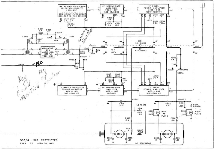
1. PURPOSE: To control the RF output of the transmitter.
2. GENERAL CIRCUIT CONDITIONS:
(a) All RF stages are keyed.
(b) For MCW,-audio oscillator (V-201) generates 800 cycles continuously.
3. OPERATION:
(a) From local position, closing the TEST key (S-208) energizes the keying relay coil (K-202A) from the 85-volt DC bias supply.
(1) Keying contacts (K-202B and C) complete the DC return paths to the filaments of all RF stages.
(b) From remote position, the keying relay (K-202) may be energized either through the remote key or through the microphone relay contacts (K-203B) controlled by the PRESS TO TALK switch in the hand set.
(c) Opening the key or press to talk switch de-energizes the keying relay.
(1) K-202B and C break the DC return paths to the filaments of all RF stages.
39
TDE-2 TRANSMITTER
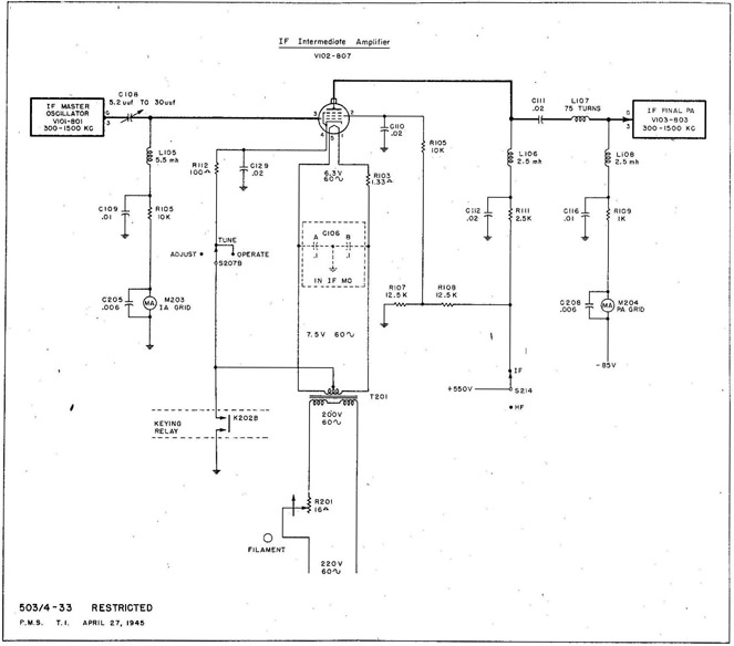
Fig. 33 TDE-2 Transmitter (AC Model) IF Intermediate Amplifier.
TDE- 2 INTERMEDIATE FREQUENCY TRANSMITTER
1. IF MASTER OSCILLATOR (300 to 1,500 kc):
(a) An 801 (V-101) in a series-fed Colpitts circuit, Class C.
2. IF INTERMEDIATE AMPLIFIER (300 to 1,500 kc):
(a) An 807 (V-102) in an un-tuned circuit, Class AB.
(1) L-106 is the untuned plate load.
(b) The coupling circuit (C-111 and L-107) will pass all frequencies between 300 and 1,500 kc.
3. IF FINAL POWER AMPLIFIER (300 to 1,500 kc):
(a) An 803 (V-103) in a conventional Class C amplifier circuit.
TDE-2 HIGH FREQUENCY TRANSMITTER
An electron coupled master oscillator and two Class C amplifiers, all conventional.
40
TRANSMITTER SERVICING
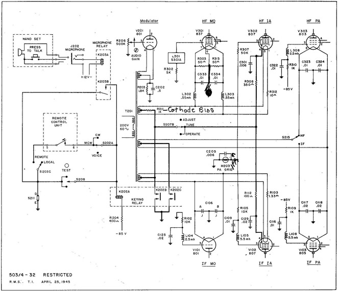
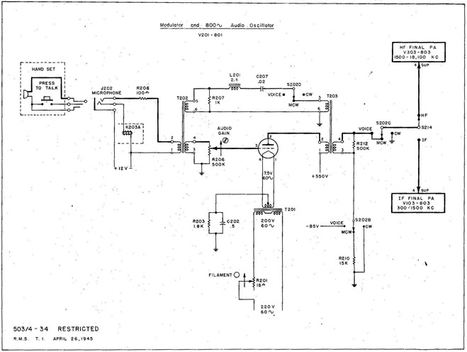
Fig. 34 TDE-2 Modulator and 800-cycle Audio Oscillator.
1. PURPOSES:
(a) For VOICE operation, to amplify the AF signal from the microphone.
(b) For MCW operation, to generate an 800-cycle signal.
2. GENERAL CIRCUIT CONDITIONS: An 801 (V-201) Class A amplifier.
3. VOICE OPERATION:
(a) The VOICE position of S-202B connects -85 volts bias to the suppressor grid of the PA being used (either V-103 or V-303).
(b) The modulator (V-201) amplifies the AF signal from the microphone transformer (T-202).
(c) The AF output of V-201 delivered to the modulation transformer (T-203) modulates the suppressor grid of the PA being used.
(d) Swamping resistor (R-212) reduces distortion due to the flow of suppressor grid current on positive signal peaks.
4. MCW OPERATION:
(a) The MCW position of S-202D connects an 800-cycle feedback circuit (L-201 and C-207) between the grid and plate circuits of V-201.
(b) The 800-cycle output of V-201 delivered to the modulation transformer (T-203) modulates the suppressor grid of the PA being used.
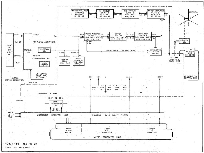
1. PURPOSE: To provide ship to ship communication over short distances.
2. FREQUENCY RANGE: 60 to 80 megacycles in crystal controlled channels.
3. EMISSION: Primarily or VOICE. A-2 or MCW also available if desired.
4. POWER OUTPUT: 50 watts for either VOICE or MCW.
5. RF STAGES: Crystal type master oscillator (15 to 20 mc), two frequency doublers and a power amplifier, all Class C. RF output to antenna through 72-ohm coax.
6. AF STAGES: Class A speech amplifier, Class AB driver and Class 13-modulator, all push pull. Armstrong type audio oscillator (1,000 cycles).
7. MODULATION LIMITER: An 84 rectifier (V4I2) used as an automatic gain control.
8. CARRIER DELAY: Keeps RF carrier on for about one second after MCW output stops.
9. POWER SUPPLY: Single unit motor generator set with 300-v and 875-v DC outputs.
10. CONTROL UNITS: Each has motor generator start-stop switch; AF volume control; hand jet switch; speaker relay and jack, for hand set, chest set and phones.
42
TRANSMITTER SERVICING
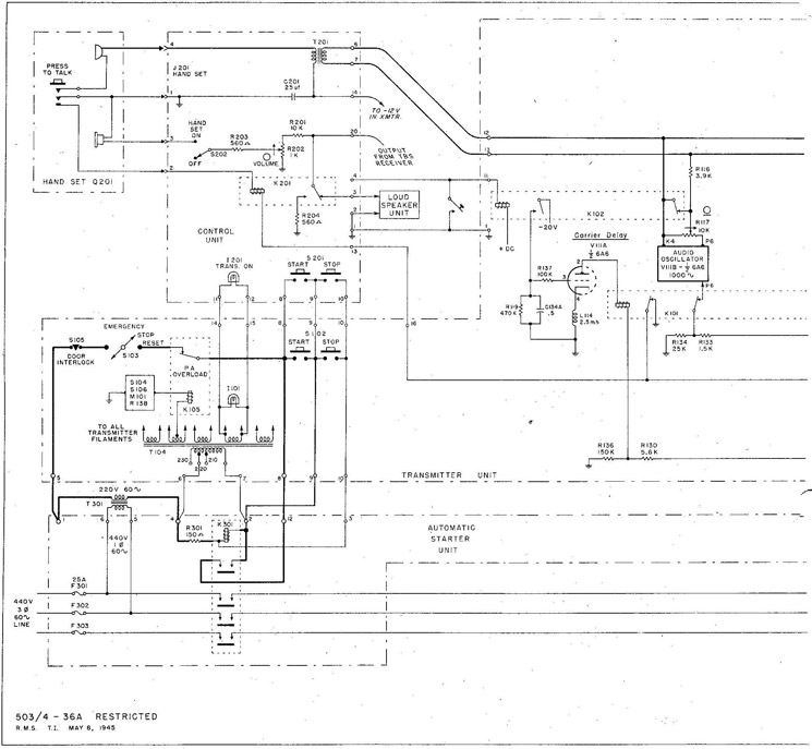
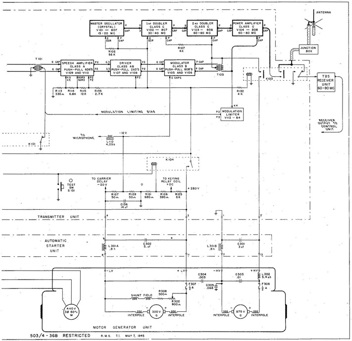
Fig. 36 TBS-6 Transmitter (AC Model) Control and Power Circuits.
1. STARTING THE TRANSMITTER:
(a) Press START button (S-102 or S-201) to energize K-301.
(1) K-301 contacts connect the motor and the filament transformer (T-104), and keep K-301 coil energized.
(b) V-111A plate current keeps K-101 energized and its contacts open.
2. PHONE OPERATION:
(a) Hold PRESS TO TALK switch closed to connect 12 volts DC to the micro-phone, and to energize K=201 and K-104.
(1) K-201 transfers receiver output from loudspeaker to R-204.
(2) K-104 connects +280 volts to the transmitter and to K-103.
(b) K-103 grounds the receiver input, transfers the antenna from receiver to transmitter, and connects +875 volts to the transmitter.
43
TBS-6 TRANSMITTER
(c) RF carrier is transmitted continuously, voice modulated during speech.
(d) Releasing TALK switch returns all equipment to receive condition.
3. MCW OPERATION:
(a) Close telegraph key to energize keying relay K-102.
(1) K-102 opens the short across audio oscillator output, and connects -20 v to the grid of V-111A to de-energize K-101.
(b) K-101 shorts out the modulation limiting bias, connects plate voltage to the audio oscillator and energizes K-104 (but not K-201).
(c) K-104 and K-103 put the transmitter, antenna and receiver in transmit condition, but the receiver and loud-speaker still serve as monitor.
(d) The RF carrier remains on while the audio oscillator is keyed.
(e) If the key is left open for more than one second, C-134A discharges through R-119 enough to allow V-111A plate current to energize K-101. The equipment then returns to receive condition
44
TRANSMITTER SERVICING
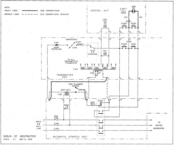
Fig. 37 TBS-6 Transmitter (AC Model) Modification to Filament Circuit.
1. AUTHORITY: C.E.M.B. - 8, 4-15-44.
2. PURPOSE: To reduce the warm-up time of the transmitter, and to avoid interrupting reception until V-111A conducts.
3. CHANGES:
(a) Remove old connections shown in broken lines in Fig. 37.
(b) Make new connections shown in heavy solid lines in Fig. 37.
(c) Mount switch in box, name plate TBS FILAMENT SWITCH, by transmitter.
(d) Drill control unit panel, install GEN. ON illuminated name plate with 1/4-watt, 110-volt neon lamp and 15-K, 2-watt resistors behind It.
(e) Change illuminated name plate on 1-201 from TRANS. ON to FIL. ON.
4. RESULTS:
(a) TBS FILAMENT SWITCH has complete control of transmitter filaments.
(b) Motor generator can not be started with TBS FILAMENT SWITCH open. (c) The control unit lamps indicate both FIL. ON and GEN. ON, but the transmitter panel lamp (I-101) indicates only that filaments are on.
45
TBS-6 TRANSMITTER
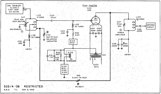
Fig. 38 TBS-6 Transmitter Power Amplifier Neutralizing Circuit.
1. PURPOSE: To cancel the effect of undesired feedback of RF voltage from plate to grid through the interelectrode capacity of a triode amplifier tube.
2. GENERAL CIRCUIT CONDITIONS:
(a) Grid neutralization of Class C.RF amplifier using type 808 tube.
(b) The PA grid connection and the neutralizing connection are made across equal and opposite portions of the coil in the balanced tank circuit (C-117 and L-103).
(c) The RF voltage fed back from the PA plate through the neutralizing capacitor (C-121) cancels the undesired voltage fed back from plate to grid through the interelectrode capacity of the PA tube (V-104).
(d) The balancing capacitor (C-120) compensates for the total capacity between the grid connection and ground, so one neutralizing adjustment will serve for the entire tuning range from 60 to 80 mc. The manufacturer specifies that C-120 should be set .exactly half open and locked.
3. NEUTRALIZING ADJUSTMENT:
(a) Disconnect plate voltage from the PA (V-104).
(b) Set the meter switch to Ig PA and tune the transmitter for normal PA grid drive.
(c) Unlock and adjust PA NEUT. screwdriver control (C-121) for minimum, change in Ig PA when POWER AMPLIFIER tuning control (C-127) is tuned through resonance.
(d) Lock the adjustment of C-121 and replace PA plate voltage connection.
46
TRANSMITTER SERVICING
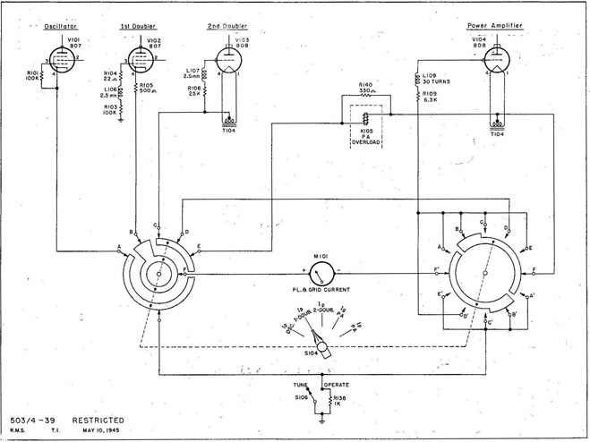
Fig. 39 TBS-6 Transmitter Meter Switching Circuit.
1. PURPOSE: To use one Meter (M-101) for measuring current in any one of five different circuits.
2. GENERAL CIRCUIT CONDITIONS:
(a) All metering is done in the cathode or filament DC return circuits.
(b) The meter switch (S-104) is a three-gang wafer switch.
(c) The meter (M-101) has a 0-200 ma movement.
3. OPERATION: The actual currents measured in each switch position are:
IP OSC.
Plate and screen current of the RF Oscillator (V-101).
IP 1-DOUB.
Plate, screen and grid current of the 1st Doubler (V-102).
IP 2-DOUB.
Plate current of the 2nd Doubler (V-103).
Ig PA
Grid current of the Power Amplifier (V-104).
IP PA
Plate current of the Power Amplifier (V-104).
47
TBS-6 TRANSMITTER
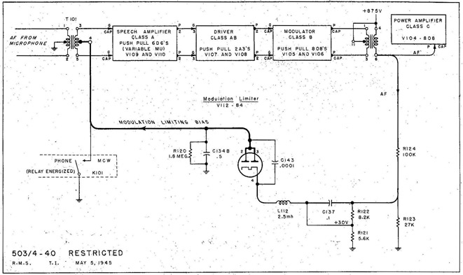
Fig. 40 TBS-6 Transmitter Modulation Limiter.
1. PURPOSE: To prevent over-modulation with high level voice signal input.
2. GENERAL CIRCUIT CONDITIONS:
(a) Variable-mu tubes (6D6's) are used in the Speech Amplifier.
(b) For PHONE operation, the MIME MCW relay (K-101) contacts are open.
(c) With no AF signal, the cathode of the Modulation Limiter (V-112) is biased about 30 volts positive with respect to the plate.
3. OPERATION BELON 75% MODULATION:
(a) The AF voltage fed from the modulation transformer to the cathode of the Modulation Limiter (V-112) is less than the DC bias.
(1) V-112 does not conduct, so has no effect on the modulation.
4. OPERATION ABOVE 75% MODULATION:
(a) The AF voltage fed to the cathode of V-112 exceeds the DC bias.
(1) V-112 conducts on negative signal peaks when the cathode becomes negative with respect to the plate.
(2) The pulses of DC Plate current from V-112 charge the filter
capacitor (C-134B) negative with respect to ground.
(3) This negative voltage is applied to the grids of V-109 and
V-110 to reduce the gain of the Speech Amplifier.
(b) With an AF signal input 10 db greater than that required to produce 75% modulation, V-110 develops enough bias for the Speech Amplifier to limit the modulation to less than 95%.
(c) Limiting of increasing signal levels is practically instantaneous.
(d) Loss of limiting bias after the signal decreases is delayed by the slow discharge of C-134B through R-120 (90% recovery in 3 seconds).