Torpedo Angle Solvers Mark 7 and Mods., Description and Instructions for Use, O.D. 4656, 1943. This describes the circular slide rule used to calculate torpedo gyro angle.
We thank Harry Lockhart, Jr. for scanning this document.
In this online version of the manual we have
attempted to keep the flavor of the original layout while taking advantage
of the Web's universal accessibility. Different browsers and fonts will cause
the text to move, but the text will remain roughly where it is in the
original manual. In addition to errors we have attempted to preserve from the original,
this text was captured by a combination of optical character recognition
and human typist. Each method creates errors that are compounded while
encoding for the Web. Please report any typos, or particularly annoying layout issues to the Mail Feedback Form for correction.
Richard Pekelney
Webmaster
RESTRICTED
NAVORD OD No. 4656
10 Sheets
Sheet No. 1
TORPEDO ANGLE SOLVERS MARK 7 AND MODS.
DESCRIPTION AND INSTRUCTIONS FOR USE
O.D. No. 4656
10 Sheets
Sheet No. 2
Torpedo Angle Solver Mark 7 and Mods.
1. PURPOSE
The Torpedo Angle Solver Mark 7 is used for solving the triangle of torpedo fire to obtain sight angle, for determining the effective range for the interconversion of target angle and target course and of target angle and angle on the bow, and for finding the base torpedo course for the base torpedo course plan. It is used principally for local control.
2. DEFINITION OF TERMS
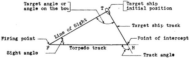
(a) The triangle of torpedo fire is illustrated by the triangle FTH of Figure 1. It is a graphic representation of the intercepting problem whereby the torpedo, a relatively low speed projectile, is directed to hit its target.
Figure 1
(b) The target is that ship or group of ships selected to be attacked.
(c) The target ship is that vessel selected to be aimed at in attacking the target.
(d) The point of aim is that part of the target ship selected to be aimed at. The standard point of aim for destroyers is the middle of the target ship.
(e) The target ship initial position is the position of the target ship when the torpedo is fired.
(f) The target ship track is the line along which the target ship is proceeding through the water when the torpedo is fired.
O.D. No. 4656
10 Sheets
Sheet No. 3
(g) The actual target speed is the target ship's speed through the water.
(h) The firing point is where the torpedo starts its run. Broadly, it is the position of the firing ship when the torpedo is fired.
(i) The line of sight is the line from the firing point to the target ship initial position. It is the direction of the point of aim from the firing ship when the torpedo is fired.
(j) The target angle is the relative bearing of the firing ship from the target ship, measured clockwise from the target ship's head through 360°.
(k) Angle on the bow differs from target angle only in that it is measured to the right or left of the target ship's head through 180°.
(l) The torpedo track is the path along which the torpedo proceeds through the water.
(m) The torpedo speed is the speed made good through the water by the torpedo while covering its designed range. It is assumed to be constant.
(n) The point of intercept is the point at which the torpedo track intercepts the target ship track.
(o) The track angle is the angle at the point of intercept measured clockwise from bow of target to the torpedo track.
Track angle = sight angle plus angle on the bow, for angles on the starboard bow. For port angles on the bow, track angle = sight angle minus angle on the bow.
(p) The sight angle is the angle at which the torpedo must depart relative to the line of sight in order to intercept a target ship which is proceeding steadily along an assumed course at an assumed speed. Sight angle is measured clockwise from the line of sight through 360°. In the triangle of torpedo fire, Figure 1, the target ship track and torpedo track are proportional to the target speed and torpedo speed, respectively. It follows that
sin sight angle = (sin target angle x target speed) / (torpedo speed)
The angle solver solves this equation.
O.D. No. 4656
10 Sheets
Sheet No. 4
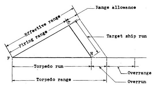
(q) The torpedo range is the normal distance to which the
torpedo will run at its designed speed. Any additional distance which it may cover is called overrange, in covering which its speed is uncertain and decreasing.
Figure 2
(r) The torpedo run is the distance between firing point and point of intercept - that is, the distance covered by the torpedo in reaching the initial target track.
(s) The overrun is the distance the torpedo will run at its designed speed after passing the target ship track.
(t) The target ship run is the distance between the target ship initial position and the point of intercept.
(u) Range is the distance of the target ship from the firing ship at any given moment. It is usually expressed in yards.
(v) The firing range is the range at the instant the torpedo is fired.
(w) The effective range is the maximum firing range at which a torpedo while running at its designed speed, will just reach the point of intercept. It is expressed in yards or as a decimal fraction of the torpedo range. Effective range varies with the shape of the triangle of torpedo fire.
O.D. No. 4656
10 Sheets
Sheet No. 5
(x) The range allowance equals effective range minus firing range. It is a margin allowed in order to insure that the torpedo run shall be less than the torpedo range. The range allowance is expressed as a percentage of the effective range.
(y) Target course (true) is the angle measured clockwise from meridian to the bow of the target.
(z) True target bearing is the angle measured clockwise from the meridian to the line of sight at the firing vessel.
(aa) Relative target bearing is the angle from the bow of the firing vessel measured clockwise to the line of sight.
(ab) In the base torpedo plan all firing ships of a
group direct their mean torpedo tracks along the true course signalled by the firing group leader.
(ac) In determining this course, the base torpedo course, the
firing group leader should select a target ship offset laterally from the middle of the target in the same direction, and by the same amount at right angles to the line of sight, that the leader is offset from the middle of his firing group.
(ad) Enemy deployed course, is the line of bearing of the division guides of the enemy's battle line, from rear to van, that is, it is the axis of his battle line formation.
(ae) Formation target angle is a bearing from the middle of the target formation (or from an assigned target ship) relative to the enemy deployed course, measured from 0° clockwise through 360°.
3. THE ANGLE SOLVER
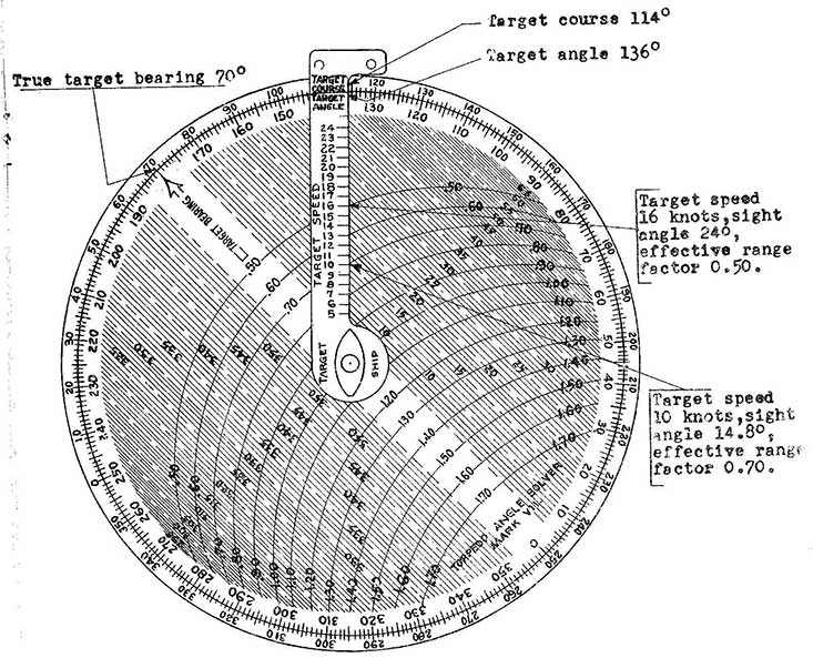
(a) Description. The angle solver is composed of two concentric discs and a runner, all mounted on the same axis. Some of the modifications have three runners. The outer disc is called the compass disc and is marked with an angular scale extending clockwise through 360°. The inner disc is called the target disc. Around its periphery is an angular scale extending counterclockwise through 360°, called the target angle scale, On the face of the target disc is a series of parallel lines, every fifth line being a dotted line, which represent sight angles, the dotted lines marking 5° increments. A series of eccentric arcs represent effective range factors expressed as proportions of torpedo range. The runner carries a system of marks along its radial edge which indicate target speed, and near its outer end are the indications "target angle" and "target course". The target angle indication registers with the angular scale of the target disc. The target course indication registers with the angular scale of compass disc.
O.D. No. 4656
10 Sheets
Sheet No. 6
(b) Use. The portable angle solver will solve for sight angle if target speed and either target course or target angle is known as follows:
(1) Having target angle. Set the runner to target angle on
scale of target disc. Opposite to target speed on the runner, find
the parallel line, representing sight angle, interpolating between
lines for a fraction of a degree, if considered necessary. Similarly,
find the effective range factor, interpolating if necessary. Examples: Target angle 136°, target speed 16 knots. Sight angle is found to be 24°, effective range factor about 0.50. See Figure 3.
(2) Having target course. Set the arrow on the rim of the target disc marked "target bearing" to the true target bearing on the compass disc. Set the runner to true target course on the compass disc. Opposite target speed on the runner pick out sight
angle and effective range factor, as for Case 1. Example: True
target bearing 70°, target course 114°, target speed 10 knots. Sight angle is found to be 14.8°, effective range factor 0.70. See Figure 3.
(3) The portable angle solver is used at the tube mounts to obtain sight angle for local control. Tube mount personnel require instruction and training in its use and in estimating target angle and target speed. It is also a valuable aid to the division commander,
together with the angle converter, in finding the base torpedo course
for firing by the base torpedo course plan.
(4) Effective range is found as follows: When the discs and runners are set for finding sight angle, note where the point on the edge of the runner marking target speed falls among the effective range factor arcs. Interpolate as necessary between adjacent arcs to find the effective range factor. Multiply this factor by the torpedo range to get the effective range.
4. THE ANGLE CONVERTER
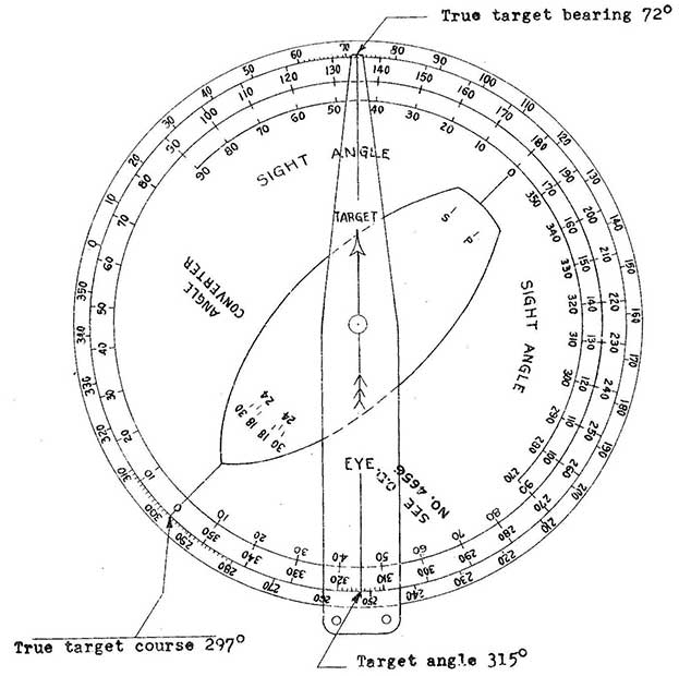
(a) Description. The angle converter is illustrated in
Figure 4. It is useful for interconversion of target angle and target
course and of target angle and angle on the bow, also for finding the base torpedo course for the base torpedo course plan.
The angle converter consists of outer or compass disc,
together with a double-ended transparent runner pivoted about the disc
axis. The compass disc carries a single angular scale extending
through 360°, arranged with the values increasing clockwise, normally indicating true bearings or courses. The ship disc carries three concentric angular scales and the outline of a ship. The outermost scale, normally indicating target angle, extends clockwise through 360°, its zero point coinciding with the heading of the ship-outline. The intermediate scale, representing "angle on the bow" to port, covers
O.D. No. 4656
10 Sheets
Sheet No. 7
only the left semicircle of the outer scale, and is marked counterclockwise from 0° through 180°. The innermost scale represents sight angles. It is marked counterclockwise from 270° through zero to 90° and extends through the second and third quadrants of the outer scale. The long end of the runner is called the "eye end", referring to the observer's eye, and the short end is called the "target end", an arrow indicating the direction of the line of sight. Inside the ship outline, near its bow and stern, appear a number of short radial marks identified with numbers and letters. These should be disregarded, as the purpose for which they were provided is no longer important.
(b) Use. Interconversions of target angle and target course are illustrated by the following examples:
(1) From actual target course to target angle. The true target bearing must be measured at the moment at which the target angle is desired. Set ship's head of ship disc to actual target course on compass disc. Set target end of runner to true target bearing on compass disc. Then eye end of runner will indicate target angle on the outer scale of the ship disc, Example: Target course 296°, true target bearing 232°. Target angle is found to be 116°.
(2) From target angle to actual target course. The true target bearing must be measured at the moment the target angle is
determined. Set target end of runner to indicate true target bearing on compass disc. Rotate ship disc (without altering alignment of runner with compass disc) until target angle comes under hair line of eye end of runner. Then the ship's head of ship disc will indicate actual target course on the compass disc. Example: True target bearing 72° target angle 315°. Actual target course is found to be 297°. This set-up is illustrated in Figure 4.
(3) To find formation target angle from enemy deployed course. The true bearing of the middle of the target formation (or
of the sector origin if endeavoring to occupy an attack sector) is required for the moment at which formation target angle is to be determined. Set ship's head of ship disc to enemy deployed course on compass disc. Set target end of runner to true target bearing on compass disc. The eye end of the runner will then indicate formation target angle on the outer scale of the ship disc. Example: Enemy deployed course 40°, true target bearing 160°. Formation target angle is found to be 300°.
(4) For interconverting angles on the port bow and target angle, use the middle and outer scales on the port side of the ship
on the ship disc. For example, an angle on the port bow of 70° corresponds with a target angle of 290°.
O.D. No. 4656
10 Sheets
Sheet No. 8
(5) To find the base torpedo course base torpedo course plan, the sight angle and true target bearing are required for the desired moment of firing. Set target end of runner to true target bearing on compass disc. Bring sight angle on sight angle scale of ship disc under eye end of runner. Ship's head of ship disc will than indicate base torpedo course on the compass disc. Example: True target bearing 70°, sight angle 318°. Base torpedo course is found to be 28°.
5. DIFFERENCES BETWEEN MODIFICATIONS
Torpedo angle solver Mark 7 has only one runner and can be used only for a torpedo speed of 27 knots. Torpedo angle solver Mark 7 Mod. 1 is similar to the Mark 7 but is used only for 29 knot torpedoes. Torpedo angle solver Mark 7 Mod. 2 has three runners spaced 120° apart and is used for torpedo speeds of 27.5, 35.5 and 44 knots. Torpedo angle solver Mark 7 Mod. 3 is similar to the Mark 7 Mod. 2 but is used for torpedo speeds of 27, 34 and 46 knots. The various discs are alike for all modifications, the variation in torpedo speed being gained by changing the spacing of the target speed graduations on the runner.