4101. Torpedo control is primarily a problem of rapidly and effectively directing a torpedo, or a number of torpedoes, in the proper direction relative to the target, in order to produce the maximum number of hits.
4102. In order to fully comprehend the problem of- torpedo control and its proper application, it is essential to have a complete understanding of a few of the basic fundamentals and definitions pertaining to torpedo fire. Whereas the control of torpedoes in motor torpedo boats is in many ways relatively simpler than in larger torpedo carrying craft, due to the lack of, or simplicity of, torpedo control equipment, the same principles and fundamentals are involved and must be followed. The following paragraphs are devoted to the triangle of torpedo fire and some of the basic definitions.
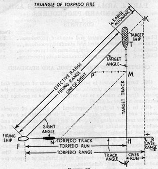
(a) Triangle of torpedo fire is illustrated by the triangle F. T. H. on page 4-2. It is a graphic representation of the interception problem, whereby the torpedo likened to a relatively low speed projectile, is directed to intercept a target.
(b) The target (or enemy) is that ship or group of ships, selected to be attacked.
(c) The target ship is that vessel selected to be aimed at in attacking the target.
(d) The point of aim is that part of the target ship selected to be aimed at. The standard point of aim for motor torpedo boats is the middle of the target ship.
(e) The target ship's initial position (T), is the position of the target ship when the torpedo is fired.
(55)
(f) The target ship track (TY), is the line along which the target ship is proceeding through the water, when the torpedo is fired.
FIGURE 28.
(g) The actual target speed is the target ship's speed through the water.
(h) The line of sight (FT) is the line from the firing point to the target ship's initial position. It is the direction of the point of aim from the firing ship, when the torpedo is fired.
(i) The firing point (F) is where the torpedo starts its run. Broadly, it is the position of the firing ship when the torpedo is fired.
(j) The target angle (HTF) is the relative bearing of the firing ship from the target ship, measured clockwise from the target ship's head to the line of sight from 0° to 360°.
56
(k) Angle on the bow. This term is more commonly used in MTB. torpedo fire than target angle. It differs from target angle only in that it is measured to the right or left from the target ships head to the line of sight, and its limits are 0° to 180°. When the target is maintaining a constant heading, target angle or angle on the bow and true target bearing, change at the same rate. Target angle and angle on the bow, therefore, should be identified by the time of observation or by an event related to time, such as moment of firing.
(l) The torpedo track (FR) is the path along which the torpedo proceeds through the water.
(m) The torpedo speed is the speed made good through the water by the torpedo, while covering its designed range. It is assumed to be constant.
(n) The point of intercept (H) is the point at which the torpedo track intersects the target ship's track.
(o) The track angle (YHF) is the angle at the point of intercept between the target ship's track and reversed direction of the torpedo track. It is measured clockwise from the target ship's head to the torpedo track, from 0° to 360°. The track angle is important in that it determines the amount of target ship length presented to the oncoming torpedo. An attractive track angle is one near 90° or 270° where the maximum amount of target area is presented to the oncoming torpedo and the maximum target maneuver, will be necessary for the target to avoid it.
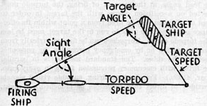
(p) The sight angle (TPM and TFH) is the angle at which the torpedo must depart, relative to the line of sight, in order to intercept a target ship which is proceeding steadily along an assumed course at an assumed speed. The term momentary sight angle is sometimes used to describe the sight angle used in firing. Sight angle is measured clockwise from the line of sight to the mean torpedo track from 0° to 360°. When the torpedo track will lie to the right of the line of sight, the sight angle will lie between 0° and 90°. When the torpedo track will lie to the left of the line of sight, the sight angle will lie between 360° and 270°. Theoretically the sight angle can have an angular value as great as 90° (sight angles of 90° and 270°) but, for battleship targets, would seldom exceed 45° and 315°. The largest sight angle to intercept a given target is encountered when the target angle is 90° (or 270°).
In practice, sight angle is usually obtained by a "solution" of the triangle of torpedo fire, using a torpedo director, an
57
angle solver, or by estimation. The torpedo control officer must know, or estimate, the target course or target angle and the actual target speed.
The geometry of a graphic solution is illustrated in figure 1, as follows: The line of sight is laid down, then the target track is cut in, either as a true course or by laying off the target angle. To a convenient scale, the actual target speed is laid off from the target ship's initial position, to some point such as M. From M an arc having a radius to the same scale, equal to the torpedo speed, is swung so as to cut the line of sight, as at P. In the small triangle, TPM is the sight angle. The torpedo track is cut in, from the firing point, parallel to the line PM. This locates the point of intercept. The angle TFH is therefore also the sight angle, by construction.
Torpedo directing is simply a problem in intercepting. From
M draw the line MN, parallel to the line of sight. It will mark off the distance FN which is by construction, equal to PM. In other words, when the target ship has advanced to M, the torpedo will be at N. The angle MNH is still the sight angle and the torpedo has the target ship on a constant bearing which is the sight angle. Thus, the torpedo is on a collision course with the target ship. (From the target ship's point of view, the torpedo which will hit it, is also on a constant bearing which is the angle on the bow, not the track angle.)
(q) Lead angle or angle of lead. This term is more commonly used in MTB torpedo fire than sight angle and differs only in that it is measured right or left of the line of sight to the mean torpedo track. Its theoretical limits are from 0° to 180°, however, practical lead angles usually are never greater than 60°.
(r) Range, as in gunnery, is the distance of the target ship from the firing ship at any given moment. It is usually expressed in yards.
(s) The firing range (FT) is the range to the target at the instant the torpedo is fired.
(t) The effective range (FK) is the maximum firing range at which a torpedo, while running at its designed speed, will just reach the point of intercept.
Effective range varies with the shape of the triangle of torpedo fire.
(u) The effective range factor is the ratio of effective range
to torpedo range. In the sketch it equals FK/FL. The effective
58
range factor for each set-up can be obtained from the Mark 7 angle solver, at the same time the sight angle is obtained.
With a small track angle (one near 0°) the effective range will exceed the torpedo range because the target advances toward the torpedo. On the other hand, with a large track angle, the effective range becomes less than the torpedo range, because the torpedo must make a stern chase. Target speed affects effective range, because the component of the target ship run is added to or subtracted from the torpedo range.
(v) The range allowance (TK) equals effective range minus firing range. It is a margin allowed in order to insure that the torpedo run shall be less than the torpedo range.
The range allowance provides against the torpedo's falling short due to control errors and in some degrees, to target maneuvers. The particular control errors it is intended to cover are a too low estimate of the firing range and an error "toward" in estimating the course of the target ship. In motor torpedo boats a range allowance of at least 4,000 yards should be used in long range torpedo fire
(w) Torpedo range (FL) is the normal distance which the torpedo will run at its designed speed. For Mark 8-3C and 3D torpedoes, it is 13,500 yards.
(x) Over range (LR) is the distance the torpedo runs beyond torpedo range. This distance is run at reduced speed and with uncertain performance.
(y) Linear target presentment is the virtual width, in yards, that a given target length presents to torpedoes advancing from a given direction relative to the target's track. In other words, it is the distance, normal to the mean torpedo track, that separates the extreme right hand and left hand torpedo tracks which would just intercept the respective ends of the target.
(z) Base torpedo course is the true direction of the mean torpedo course expressed in degree.
4104. Salvo fire.
(a) A torpedo salvo is a number of torpedoes, directed at the same target fired closely enough together, to constitute a simultaneous menace. Single ship salvo-one fired by one vessel. Group salvo-is composed of several single ship salvos. Section, division, and squadron salvos are forms of group salvos.
(b) Full salvo of torpedoes in motor torpedo boats, is a salvo comprised of all torpedoes normally carried on board.
59
(c) Partial salvo of torpedoes in motor torpedo boats, is a salvo comprised of part of the torpedoes on board.
(d) Mean torpedo track is the average as regards both direction and position of the tracks of the different torpedoes comprising the salvo, assuming all runs normal. It indicates the basic direction of the salvos.
4105. Time elements in firing torpedoes.-
(a) The firing interval of a torpedo is the time interval between the control officer's mental decision to fire and the instant the torpedo takes the water. For electric firing this interval should not average more than 1.5 seconds. All electric firings should be paralleled by emergency percussion firings.
(b) Emergency percussion firing is when personnel stationed at the tubes, strike the torpedo impulse chamber firing pin with a mallet, upon the order to fire torpedoes. It should be standard practice to use this method of firing, whether electrical firing circuits are working or not.
(c) The salvo interval is the time interval between successive discharges which comprise the salvo or the time interval between launching first and last torpedoes of a salvo. Salvos of torpedoes are separated into discharges in order to reduce the chance of torpedoes colliding with each other near the firing point. In boats carrying four torpedoes with two on each side, after torpedoes should be discharged before the forward ones if all four torpedoes are to be fired in the same salvo. In firing all four torpedoes, at least five seconds should elapse between discharge of the after pair, and discharge of the forward pair.
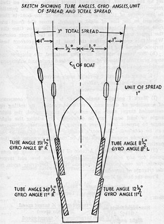
4106. Spread and gyro angles.-
(a) A spread is a number of torpedoes fired on divergent courses or on parallel courses. If fired on divergent courses, the torpedoes cover a front which increases in width with length of torpedo run. If fired on parallel courses, the torpedoes are launched at intervals of time, in order to form the spread, and the front remains at a fixed value determined by the spacing at the time of firing. The term "spread" may be expressed in degrees, as a 20° spread. The basic purposes of spreads are to compensate for errors in estimating target course and speed, and to counteract target maneuvers (using the shotgun method instead of the rifle).
(b) The unit of spread is the angle separating the tracks of adjacent torpedoes in a single-ship spread. It equals the
60
amount of spread divided by one less than the number of torpedoes comprising the spread.
(c) Gyro angle is an angle applied in the mechanism of a torpedo gyro before firing. The torpedo, immediately upon launching, turns through this angle and straightens out on a course which differs by the amount of that angle from the direction of the torpedo tube at the moment of firing. Gyro angles set on torpedoes fired from motor torpedo boats are usually small and only sufficient to compensate for tube angles used and to provide for a small spread. Gyro angle is referred to the axis of the torpedo, or what is the same thing, to axis of the tube. It is measured from 0° clockwise through 360°. In motor torpedo boats, gyro angles are referred to as so many degrees right or left i. e., the number of degrees, and direction the torpedo turns through, after leaving the tube.
(d) A spread gyro angle is a small difference between the gyro angles of adjacent torpedoes. It causes these torpedoes, when fired in a salvo, to diverge by the amount of the difference. The primary purpose is to secure accurate torpedo distribution in a spread, but a secondary purpose of considerable practical importance, is to reduce the prospect of torpedo collisions near the firing point.
(e) The basic gyro angle is the average of the gyro angles of a salvo of torpedoes at the instant of firing. It is the reference gyro angle.
4107. Tube angles.-
(a) Tube angle is defined as the angle relative to the firing ships head at which a tube mount is trained. It is measured clockwise from the firing ships head to the axis of the torpedo tube, from 0° to 360°. In motor torpedo boats the tubes are normally fixed-that is, they may be trained out a small amount to permit the torpedo to clear the boats side, and then they are secured in that position. Except when the probability of firing torpedoes exists, the tubes are trained in, and secured. The amount that the tube can be trained out, depends on the design of the boat. When four torpedo tubes are carried, the tube train angle limits, of after tubes, usually differ from the forward tubes by a few degrees, in order to permit after torpedoes when launched, to clear forward tubes. In motor torpedo boats the tube angles are customarily referred to as so many degrees right or left of the centerline of the boat.
(b) Standard tube angles, gyro angles and spreads. The following table gives the tube train angles, gyro angles,
61
resultant unit of spread, and total spread for the PT 20 type of bow launching motor torpedo boats. (See page 4-9 for illustration.)
Tube No.
Tube train angle
Gyro angle
Unit of spread
Total spread
Forward starboard No. 1
8 1/2 ° R
8° L
1°
--
Forward port No. 2
8 1/2° L 351 1/2°
8° R 352°
1°
3°
Aft starboard No. 3
12 1/2° R
11° L
1°
--
Aft port No. 4
12 1/2° L347 1/2°
11°R349°
1°
--
(c) Gyro angles are normally set on the torpedoes before they are placed in the tubes. These settings should be carefully checked by an officer to see that the settings are in the right direction and correspond to the standard setting for the particular tube the torpedo is loaded into.
4108. Firing definitions.-
(a) Curved fire is any method of fire using gyro angles. The type of firing used in motor torpedo boats is curved fire ahead, with tube angles fixed. The torpedoes are than directed by conning the ship to the desired base torpedo course.
(b) Curved fire ahead is a form of curved fire in which the mean torpedo track lies along or close to the firing ship's heading, at the moment of firing. This method permits all torpedoes on board to be discharged in a single salvo.
(c) Single firing is the firing of only one torpedo at a time. When two torpedoes on the same side are to be discharged in a Salvo, five seconds should elapse between successive discharges, and the after torpedo should always be discharged first.
(d) Pair firing is the simultaneous firing of one torpedo from each of two or more tubes. In motor torpedo boats pair firing will consist of the firing of one torpedo from each of two opposite tube mounts at the same time. In other words, firing the starboard and port after torpedoes simultaneously, and then the starboard and port forward torpedoes simultaneously. In this case five seconds should elapse between the discharge of after and forward torpedoes.
4109. Torpedo control system.-
(a) Torpedo director. (See illustration on page 4-12.) This is a practical and simple director which has been used in some
62
squadrons. It solves the triangle of torpedo fire by mechanical means, when properly set up. It consists of two arms, one representing target track and the other representing torpedo track.
FIGURE 29.
The target track arm is graduated for target speed and is rotatable relative to the torpedo track arm. The target track arm carries a sliding block on which a front sight is mounted. The torpedo track arm is made in two parts, one
63
part of this arm is graduated for torpedo speed, carries the rear sight, and slides in and out of the other part, which is stationary. The stationary part of this torpedo track arm is mounted along or parallel to the center line of the boat. To set up the director, torpedo and target speeds are set on their respective arms and the target track arm is aligned parallel to the course of the target. The course of the boat is then changed so the line of sight extended, across the front and rear sight posts, intersects the target at the same time that the target track arm is aligned parallel to the target course. When this condition exists the boat is on the correct base torpedo course for the conditions set up.
(b) For vessels without directors installed, the simplest and most practical methods of solving for lead angle and subsequent base torpedo course are:
1. using the Mark 7 portable angle solver.
2. using lead angle tables.
3. using the seamans eye.
(1) Mark 7 portable angle solver is an "iswas" composed of a number of discs and a celluloid runner. By setting up estimated target angle and estimated target speed, the sight angle or lead angle can be obtained. By adding the sight
angle to present true target bearing, the base torpedo course can be obtained. The boat's heading is then changed to the base torpedo course, which will be the firing course for that particular observation.
(2) Lead angle tables. A table of lead angles may be computed for any combination of angles on the bow and target speeds, for one particular torpedo speed. Referring again to the triangle of torpedo fire:
If torpedo speed is constant, different values may be substituted in above formula for target angles and target speeds and a table of sight angles computed. By using this table, in conjunction with relative bearing marks painted every 5° or
64
FIGURE 30.
FIGURE 31.
65
10° on the canopy of the boat, from ahead to on each beam, the bearing of the boat can be changed to correspond to the proper lead angle. On making the approach to fire torpedoes, it will be necessary to take frequent observations and change the heading of the boat to correspond to the correct lead angles, because, unless the boat is making the same speed as was used for torpedo speed in the computations, the bearing of the target, the target angle and hence the lead angle, will continually change.
(3) Seamans eye method of firing. This method will probably be used to a great extent in motor torpedo boats when emergencies arise where time or darkness will not permit reading tables, making calculations or setting up a director. The principle of the seamans eye method of firing is the same as the hunter uses when he fires at ducks or birds on the wing, in other words leading a moving target. The amount to lead the target will depend on the target's course and speed. Whether the lead angle is correct or not will depend on whether the control officer has a "seamans eye". In general the rule to follow is, "If it looks big it is big". If the full area of the target is presented to the eye, it will take a substantial lead angle to intercept him, unless the firing range is extremely small and the torpedo speed is extremely large. Very excellent training can be had, when two boats are operating together by placing one boat on a constant course and speed and the other make! approaches for firing, estimating the amount of "lead" required. After simulating firing, follow through, with the boat making the same speed as the torpedo. These drills will indicate that there is a general tendency to underestimate lead angle. A good rule to following in using the seaman's eye is to estimate "lead angle" and then add about 5° for good measure.
4110 (a). Methods of firing.-Whatever the method of solving for the lead angle, at the moment of firing, the torpedo must be directed on a collision course with the target in order to intercept it. It must also be fired from a point within its effective range and hence the torpedo run to the target, must be less than the torpedo range. Torpedoes can be fired electrically from the conning station or by emergency percussion, by personnel stationed at the tubes. The standard method is to parallel electric firing with emergency percussion firing in every case. ( See par. 4105b.) For daytime firing, suitable visual signals are provided to direct that torpedoes be launched. A night,
66
the firing of, and number to be fired, will usually be directed by word of mouth.
(b) Torpedoes carried. Torpedoes carried on motor torpedo boats will consist of the following types:
(c) Condition to torpedo battery. ( See Conditions of readiness of armament in back of book.) At the time of tiring torpedoes the battery will be in the following state of readiness:
(1) Torpedoes properly loaded in tubes in the fully ready condition, proper depth and gyro angles set.
(2) Tubes trained out to maximum position and secured to stops. Tubes in all respects clear and ready for firing.
(3) Primed and dry impulse charges loaded in the impulse chambers.
(4) Firing pins in impulse chambers in contact with impulse charge primers.
(5) Tube tripping latches in contact with torpedo starting levers.
(6) Boat headed on base torpedo course.
(7) Personnel stationed at tube mounts to parallel electric firing with emergency percussion firing.
(8) Electrical firing circuit closed.
(d) Firing speeds. Although torpedoes normally may be discharged at high firing ship speeds, it will be standard practice to retard throttles at the moment of firing torpedoes and allow the torpedoes to clear, before retiring or changing course. In this connection, it will be necessary to steer the boat as carefully as possible at the moment of firing, as any amount of yawing will throw the torpedo off the desired course. It is also desirable to have the boat on a steady keel, with the tubes as horizontal as possible at the moment of firing. The attitude of the firing vessel at this time, may affect the performance of the torpedoes.
(e) Depth settings. The depth settings to be used on torpedoes carried aboard motor torpedo boats will be in accordance with the table given below. If no means exist of setting
67
torpedoes for depth after they are in the tubes, the settings should be staggered on the individual torpedoes on board, between 14 and 18 feet. These settings are prescribed for a mechanical type warhead exploder only.
Depth settings
Battle cruisers, battleships, aircraft carriers
Heavy cruisers, light cruisers, large auxiliaries, submarines
Destroyers, small auxiliaries
Forward tubes, 18 feet
16 feet
12 feet.
After tubes, 20 feet
14 feet
10 feet.
4111. Torpedo control procedure.-
(a) With tubes trained out on each side of the boat and with gyro angles set as prescribed in art. 4107b, the torpedoes, when fired in the proper manner will form a symmetrical salvo. (See page 4-9.) The boat when on the proper firing course will be headed down the mean torpedo track of the salvo. As previously stated, in a standard 4 torpedo salvo, one torpedo from each after tube is fired simultaneously and five seconds later, one torpedo from each forward tube is fired simultaneously. Extreme care must be used in conning the boat during the period of firing.
(b) Primary method.
(1) Boat captain or control officer orders "stand by to fire torpedoes-Full salvo or tube No. ____ ," and heads boat on approximate collision course.
(2) Boat captain then places boat on proper heading which is base torpedo (firing) course, by means of director, lead angles or seamans eye.
(3) Torpedoman checks tripping latch, firing pins, etc., to see if tubes and torpedoes are in all respects ready, then reports "battery or tube ____ ready."
(4) Torpedoman and one engineering rating stand by torpedo tubes for emergency percussion firing.
(5) Boat captain or control officer orders "fire torpedoes or fire tube No. ____" making appropriate arm signal, and retards throttles.
(6) Boat captain or control officer closes electrical firing circuits using care to fire after torpedoes first.
68
(7) Tube personnel use emergency percussion firing methods on all tubes designated to fire, taking care to fire those in after tubes first, unless otherwise designated.
(8) After torpedoes are clear, increase speed and retire, unless otherwise directed.
(c) Emergency method. Under certain conditions rapid action will be required and time may not permit many orders to be issued or an accurate base torpedo course to be calculated. It is also possible that all personnel will be required to man and fire guns and no one will be available to stand by the tubes. In this case the boat captain should swing the boat to an approximate base torpedo course by seamans eye and fire torpedoes immediately by electricity. If the primers fail to fire, any one available should be directed to use emergency percussion methods to get them out.
CHAPTER 2. GUNNERY ORDERS AND STANDARD
PROCEDURE
4201. Personnel, training and safety precautions.-Each member of a MTB crew must be thoroughly familiar with and capable of operating all armament on board. Training toward higher standards of personnel operating efficiency should be continuous. Safety orders will be posted in conspicuous places near the ordnance equipment concerned. These safety orders must be rigidly observed at all times.
4202. Care and upkeep of weapons.-The gun armament on MTB's consists of rapid fire machine guns which require meticulous care and constant routine maintenance to keep them in proper condition for effective use. They are exposed to large quantities of salt spray and even under most favorable conditions will receive rough treatment. Every effort should be made to keep all guns in a high state of readiness. In this connection light canvas muzzle bags should be fitted on guns when it is necessary to keep them trained on bearings where salt water is likely to fill up the bores. In case of emergency the gun can be fired with muzzle bags on.
4203. Fire control.-Gun control in MTB's is primarily a matter of firing the maximum number of guns at enemy targets within machine gun range. The .50-caliber and 20-mm. machine guns are short range weapons with a very high rate of fire. Their fire must be held until the target comes within their
473319-42-6
69
range. Indiscriminate firing at distant targets must not be permitted. The ammunition for these guns is expended very rapidly, only a limited amount can be carried on board, it is precious and for use at the proper time. These guns are for defense against dive bombers, strafers, low position glide bombers, and for offense or defense against small surface craft, large surface craft (during close in or night attacks) and submarines on the surface.
4204. Fire distribution.-No standard fire distribution plans are necessary. During night torpedo attacks MTB's will seldom, if ever, be in formation. During daylight torpedo attacks it is doubtful if the attack can be pressed in to machine gun range. Against aircraft, the nearest and most menacing target should be engaged and concentrated on.
4205. Surface targets.-If surface craft are engaged by MTB's in formation, all enemy ships being attacked must be kept under fire. Whenever the number of torpedo boats exceeds the number of enemy ships, the fire will be distributed as evenly as possible. Crossfire should be avoided. Maneuvers should be made in a manner that will not mask the fire of any boat, but if, possible to mask some of the enemy's guns.
4206. Aircraft targets.-When engaging enemy aircraft, maneuvers should be made in a manner that will afford mutual fire support and avoiding enfilade. (See art. 3903.)
4207. Directing fire.-When engaging enemy surface craft, fire should be directed at the bridge, control stations, exposed gun crews and (if at night) searchlights. Against a submarine, it is possible with well directed machine gun fire to prevent the submarine from manning his guns, and either force him to surrender, or to submerge and lose the men on deck.
4208. Firing at night.-During night or low visibility an MTB should never open fire against a surface ship unless it is certain that the MTB has been sighted or that the surface ship itself is poorly armed. During daylight high visibility, it can be assumed that an MTB has been sighted by the time the enemy is within gun range.
4209. Orders for opening fire.-When in formation boats should follow the movements of the leader in opening fire. However, any boat observing aircraft actually attacking should fire a short burst in the direction of the attack if it is believed the other boats have not seen the plane or planes. Vessels observing enemy surface craft or distant aircraft which it is believed the leader has not seen, should pass the information
70
by visual signal or radio. Orders to open and cease fire will always be given from the conning station and must be strictly obeyed.
4210. Opening fire ranges.-The maximum opening range for 20-mm. and .50-caliber machine guns should be 2,000 yards. This is the "tracer burn out" range for both weapons and is also the limit of their accuracy. When firing at aircraft, opening fire ranges considerably less than 2,000 yards should be used in order that fire will not have to cease due to an expended magazine in the case of the 20-mm. and an overheated gun in the case of the .50-caliber. Recommended ranges for opening fire are:
Dive bomber-1,500 to 2,000 yards.
Strafer, low position glide bomber or torpedo plane-1,000 to 1,500 yards.
NOTE.-MTB's can be used to a great advantage in protecting large vessels against surprise torpedo plane attacks by taking station at approximate points of torpedo release thus subjecting these planes to much additional gunfire.
4211. Firing on attacking aircraft.-If planes are attacking in rapid succession, fire should never be continued on planes which have passed overhead. It should always be directed at incoming planes. The principle of engaging the nearest and most dangerous targets applies.
4212. Lookouts.-The importance of keeping an extremely bright lookout in all directions cannot be overstressed. Each man having a battle station above deck should be assigned a search sector. Dive bombers invariably attack from the direction of the sun. The lookout assigned that sector should wear dark glasses. MTB engines are as loud as those of an airplane. This factor may enable a plane to attack a boat that is "not alert" before any gun on the boat can be brought to bear.
4213. Standard terms.-Definitions of terms used in control of machine gun fire are as follows:
(a) "Track" is an order given before "commence firing" and means bring the guns into firing position and follow target.
(b) "Tracking" is a general term meaning the art of moving the gun smoothly and steadily keeping the sights or tracers constantly on the target.
71
(c) "Individual tracer control" is a method of fire in which the gunner plays the tracer stream on the target in same manner as he would water from a hose.
(d) "Tracer control" is a method of firing in which the gunner uses tracers at the target, to assist in tracking.
(e) "Sight control" is the method of firing in which the gunner uses sights in tracking the target.
(f) "Tracer cut back or tracer curve illusion" is the apparent curve in the path of tracers as they pass a moving target. This is due to the relative movement between target and tracer.
(g) "Superelervation" is the added angle of elevation necessitated by a projectile's trajectory. It is the angle between a line from gun muzzle to any given point in space and the axis of the gun when laid so that projectiles will hit the given point.
(h) "Slant range" is the range along the line of sight from gun muzzle to the target.
4214. Individual tracer control will normally be the method used in firing machine guns on MTB's. Using this method, the gunner must not sight along the gun barrel while firing because in so doing, he is unable to observe tracers correctly. He must assume a relaxed position behind the gun and focus his eyes on the target. With his eyes so focused, he is best able to distinguish where the tracers are going in relation to the target. When hitting, tracers appear to be going through target in a curved line (tracer cut back). Do not attempt to follow tracers from gun. Concentrate on area around target. The gunner must track smoothly, always moving gun in direction of target course, never toward the rear of the target. If he is ahead of the target, he should slow his rate of track until the target enters the tracer stream, then resume correct rate. When behind, make a bold correction to bring tracers ahead of target.
4215. Tracer control wherein the gunner aims with sights but the tracers are observed at the target to assist in tracking and hitting. This method will be used:
(a) With 20-mm. fire when the Mark 14 gunsight is installed.
(b) If the ratio of tracers becomes less than one in five, due to scarcity of tracer ammunition.
4216. Mark 14 gunsight.-The Mark 14 gunsight is a gyro lead-computing sight which greatly increases the accuracy of
72
20-mm. fire directed at rapidly moving targets. The sight is mounted directly on the gun, and requires no stabilized reference position or connections to the gun trunnion or ship's deck. The equipment is of the optical reflex type in which the line of sight, as indicated by an illuminated recticle, is displaced from parallelism with the gun bore. The angular displacement, or lead angle, corrects for the motion of the target during the flight of the projectile and introduces the necessary superelevation. The gunner swings the gun so as to hold the illuminated reticle on the target and another member of the gun crew makes the required adjustments for range effects by means of a manual control. This is usually done by first setting an estimated range and then introducing spots as prove necessary from tracer observation.
If tracers become less than one in five, ring sights should be installed on guns and tracer control used. All personnel should know how to aim using ring sights. The attitude and speed of the target determines the aim-off necessary. The speed rings indicate the amount of lead to be given for the target speed component across the line of sight and not the lead for the actual target speed. The tracers should be observed at the target to aid in determining the correct aim-off. "Smooth tracking is essential to tracer control."
4217. Sight control becomes necessary if no tracers are available. The discussion of tracer control applies except that there are no tracers to observe passing the target.
4218. Conditions of readiness.-For the condition of readiness of the gun battery see paragraph ___.
4219. Routines-Instruction books.-Routine upkeep, maintenance and overhaul forms will be provided and rigidly adhered to. The following publications should be used as guides and references in connection with the gun battery:
MTB familiarization pamphlet.
Bureau of Ordnance Manual.
O.P. 813-20-mm. A.A. gun and mount.
T.M. 9-12-25 -50-cal. B. A. M.
T.M. 9-12-26 -50-cal. B. A. M.
O.P. 529 -.45-cal. Thompson submachine gun.
O.P. 68 -.45-cal. Colt automatic pistol.
O.P. 595 -.30-cal. Springfield rifle.
O.P. 596 -.30-cal. Springfield rifle.
73
CHAPTER 3. DEPTH CHARGE ORDERS, STANDARD PROCEDURES AND NOTES ON SUBMARINE
4301. Types of depth charges.-Depth charges carried aboard motor torpedo boats may be one of the following types:
Mark
Weight of charge
Depth settings
Pounds
Feet
Mark 3
300
50-300
Mark 6
300
30-300
Mark 7
600
30-300
Ordinarily the 600-pound charges are not carried unless smaller charges are not available. The depth charge racks mounted on motor torpedo boats accommodate 300-pound charges only, and if 600-pound charges are carried, they must be lashed on deck.
4302. Mark 6 charges.-Mark 6 charges should be carried whenever available, since the 30-foot depth setting is suited to shallow waters where motor torpedo boats are likely to operate.
4303. Condition of readiness.-During peacetime, depth charges if carried on board, will have pistol and booster mechanisms removed and placed in designated stowage. During wartime depth charges will be kept either in the "normal" condition or the "ready" condition. (See Armament Conditions of Readiness.)
Large white marks extending from the depth setting graduations on the pistol and to the outer periphery of each charge should be painted with corresponding large white numbers denoting depth settings. This will facilitate setting depths at night.
4304. Depth settings.-Normally the four forward charges should be kept set on 50 feet and the after four on 100 feet-depth of water permitting. This provides the best settings for the most likely encounter with enemy submarines, that of sighting his periscope close aboard or catching him on the surface at night. Under other conditions depth settings should be staggered among the charges on board. Charges should be dropped in rotation from each side working from forward aft. This will provide a pattern and tend to keep the boat on an even keel.
74
4305. Depth charge sinking times.-The sinking times of depth charges dropped from MTB's are approximately as follows:
Depth
300 or 600- pound charge
Feet
Seconds
30
6
50
8
100
14
150
20
200
26
250
32
300
38
For a minimum depth setting of 30 feet MTB's should be making maximum speed when dropping charges to prevent damage to own boat. For deeper settings speeds may be decreased but only with caution. To prevent countermining charges should be spaced horizontally by at least 50 feet.
4306. Personnel training.-Frequent drill of personnel in setting the depth settings on depth charges should be carried out. All hands must be fully capable of conducting an attack and launching charges as there will probably be times when emergency conditions will preclude everyone getting to their regular battle stations. The importance of celerity in making the attack cannot be overstressed, since the possible area in which the submarine may be, increases as the square of the elapsed time.
4307. Procedure in attacking a submerged submarine.-In a coordinated operation if several MTB's are present, care must be taken that vessels are well deployed in a line. The cardinal sin in a coordinated operation is for one boat to get behind another in making an attack, thus preventing the first boat from dropping his charges.
The first and basic essential is to reach the submarine's position and drop depth charges with all possible speed. Since the submarine will undoubtedly withdraw its periscope and submerge to considerable depth as soon as attack is started, the attacking vessel is faced with:
(a) Keeping track of the bearing of the point at which submarine was last seen.
(b) Determining distance to that point.
75
(c) Deciding what "lead" to make for movement of submarine between time of last sighting and time depth charges explode.
4308. Keeping track of bearing.-Keeping track of the bearing should not be difficult if a compass bearing is taken, or the point lined up with a fixed object ashore. Correction must be made for own ship's turning circle in turning to the attack; this depends on angle of turn, and range to submarine.
4309. Determining distance.-The most difficult problem is that of determining the distance to run before starting to drop depth charges. The common error is to think in terms of land topography and place undue confidence in one's ability to recognize, upon reaching it, the spot at which the submarine was last seen. But once the periscope has disappeared, it almost always develops that no distinguishing marks can be found on the surface of the ocean, and the attacker finds himself unable to determine when he has run the proper distance. Hence it is important to estimate the distance to the periscope before it disappears, and coincidentally start a stopwatch or note the clock time. Then the proper time of run can be determined from speed-time-distance tables. Admittedly, this method involves the probability of error in range estimation, and involves consideration of acceleration of own ship; but unless there is some continuing indication on the surface to show the point of submergence, it is the best method available. Drill is required to ensure that the estimation of range, and starting of stopwatch, will not be forgotten in the excitement caused by the contact. Practice in estimating ranges is important. When patrolling at a known speed, estimates can be checked by clocking the times required to pass driftwood, etc., sighted ahead.
4310. Lead angle for attack.-The amount of "lead" to allow for movement of the submarine depends on many variables, the principal ones being speed of attacking ship, submerged speed of submarine, and relative bearing of attacking vessel from submarine. The problem should be studied in detail on a mooring board; as a thumb rule, the following angles of lead are suggested. These have been worked out on the basis of a submarine speed of 8 knots (the maximum), and assuming a constant submarine course, which conditions do not always obtain.
76
Lead angle for attack
Speed of attack (knots)
Submarine speed, 8 knots (depth charges set for 100 feet)
Relative bearing (angle on submarine bow) of own ship from submarine (average range 1,000 yards)
0
30
60
90
--
180
150
120
--
20
0
14
25
27
25
0
12
20
23
30
0
10
17
19
35
0
9
15
17
40
0
8
14
15
4311 (a). Importance of lead.-This is again emphasized and it is repeated that the submarine will usually have way on and the one place he will not be is the exact spot where he was last seen.
(b) Attacks on submarines on bottom.-A submarine when attacked in shallow water may lie on the bottom either because of damage sustained or in an effort to throw off pursuit. Under these circumstances an attack should be made using depth charges set to detonate on the bottom. The standard depth charge can be so set by the following method:
(1) Drill or puncture a small hole in the safety cap.
(2) Set the charge to a depth which is less than the depth of water.
(3) Replace safety cap and drop charge with it on. When the charge is dropped it will sink to the bottom before sufficient pressure has built up to actuate firing mechanism.
4312. Use of charges and dropping.-When proceeding to attack the words "stand by depth charges" should be given and if a howler is installed it should be sounded. Personnel should then stand by racks, remove toggle pins on first charges and wait for signal from conning officer to pull safety forks and, release the first ones, moving to the next charges after releasing the first ones.
Once a good opportunity presents itself to attack, depth charges should be used liberally, as succeeding contacts if any, are not likely to be as good. In this connection if only one
77
motor torpedo boat is available to take part in the attack it will be good practice to save one or two charges in case the submarine is forced to the surface momentarily. It will also, be standard practice to remain in the area until other antisubmarine vessels arrive. If vessels with sound apparatus are in the vicinity they should be summoned immediately.
4313. After depth charging.-After an attack is made an alert and vigilant lookout should be kept for the submarine coming to the surface or being momentarily blown to the surface by the charges. Sometimes depth charges may so disturb the water as to cause the submarine to break surface. In the latter event it should be closed as rapidly as possible and torpedoed or further depth charged but above all it must be prevented from manning its guns. Thus the entire armament of the motor torpedo boat must be in instant readiness and guns trained on the bearing of the submarine.
4314. Aircraft assistance.-Aircraft can be of great assistance in locating submarines on the surface, or if not submerged at too great a depth (under good conditions, they have been located at depths up to 100 feet). Therefore surface craft should know the procedure used by aircraft to indicate the presence of a submarine. The standard procedure is for the plane to make repeated dives over the submarine and to drop a smoke float as close as possible. This float emits white smoke, and a small flame. The surface vessel should close the position indicated, keep the submarine submerged, and watch for further guidance from the aircraft. If the aircraft indicates a position of the submarine which can be reached by the surface vessel in less than a minute, one or more depth charges set for the 50-foot depth should be dropped at the position indicated by the aircraft. While the chance of actually destroying the submarine is small, its crew will be harassed.
4315. Upkeep.-Depth charge pistols and boosters should be frequently removed from the cases and inspected. Instructions for the testing maintenance and overhaul of pistol and booster mechanisms may be found in O.P. 555. Descriptions and features of operation will be found in O.P. 747. Depth charge racks should be frequently examined for fractured members and maintained in proper operating condition. Standard routine upkeep sheets should be followed and rigidly adhered to.
4316. Notes on submarine characteristics.-(a) The full speed of a submarine on the surface varies according to her design and may be anything from 10 to 22 knots. A large modern
78
submarine may have a cruising range of 10,000 miles and more, and hence be able to conduct extensive operations without refueling.
(b) The full speed of a submarine submerged may be taken as 10 knots, but due to the limited capacity of the storage battery, this can only be maintained for about 1 hour. If, however, the submerged speed is kept down to the minimum, say 3 knots, this can be maintained for 24-30 hours.
(c) This limitation of submerged endurance is a most important point to bear in mind. When the battery is exhausted, the submarine must either come to the surface to recharge, or rest on the bottom (if the depth is not too great). Even so, she cannot remain on the bottom indefinitely and must eventually come to the surface to recharge. Therefore, a submarine when submerged will much prefer to work at a low speed in order to conserve the battery. Any harassing action which forces the submarine to use high speed while submerged, and prevent it from rising to charge batteries, is thus very valuable, even though no immediate results may be apparent.
(d) Contrary to popular opinion, a submerged submarine can remain in a static condition, without headway. This requires, however, a rather delicate balance, and the submarine will generally prefer to rest on the bottom, provided the depth of water is not over 50 fathoms and the character of the bottom is suitable.
(e) A submarine on the surface may be assumed to be always ready for diving. By so-called "crash diving" a submarine can submerge to periscope depth (50-65 feet) in about 30 seconds, to 100 feet in about 70 seconds and to 200 feet in about 110 seconds. Rough weather will probably increase the above times slightly. Generally speaking the smaller the submarine the quicker it can submerge.
(f) The following action is to be expected when a submarine crash dives:
(1) Escaping air from main tank vents all along the upper deck will make a loud noise and cause spray. Later, as the upper deck submerges, bubbles will appear.
(2) The submarine will go full speed until under water, turning beam-on to the sea.
(3) In order to reduce the danger of a break-surface the submarine will go to a depth of at least 80 feet and probably to 200 feet or more.
79
(4) The water where the submarine dived will form a slick, similar to a ship's wake. A swirl will be left where the bridge goes under.
(5) Periscopes are always housed and invisible when on the surface, but one will probably be put up as the submarine dives in order to take a last view of the situation.
(g) Enemy submarines probably are able to withstand pressures equivalent to 500-600 feet. However, they will seldom dive by choice to greater than about 350 feet, and will stay at periscope depth whenever possible, the better to survey the situation.
(h) All submarines, except the smaller type, usually carry one or two guns of 3- to 6-inch caliber. They are also equipped with machine guns. In fact, submarines will very possibly have a much more powerful gun battery than the small patrol vessels which hunt them; but the submarine is at a distinct disadvantage in that being thousands of miles from her base, the slighted damage which she sustains may prove fatal.
(i) Most submarines have two periscopes, but use only one at a time. The diameter of the exposed part is between 11/2 and 5 inches, and the periscope can be raised or lowered at will, while the submarine maintains a constant depth. With periscope fully extended, the distance from top of periscope to deck is about 33 feet (to keel, 55 feet). It is common practice to expose the periscope only intermittently, extending the top from 1 to 4 feet above the surface for a period of 5 to 10 seconds.
(j) The periscope leaves a "feather" (wake) which varies with the speed, and which often is easier to see than the periscope itself.
(k) Submarines frequently lie on the surface in the awash condition, with only the conning tower above water. This permits use of the Diesels, while at the same time facilitating quick submergence, and reducing chances of detection.
(l) Enemy submarines have used this "surface awash" condition in a large percentage of their night attacks, especially in night attacks against convoys. They approach in the awash condition, running on Diesels, then fire their torpedoes and either submerge or retire at high speed on the surface.
(m) The firing position most desired by a submarine is from 45° to 60° or the bow of the target, at a range inside of 2,000 yards. Thus the first aim of an escorting vessel is to deny this favorable position to the submarine. A vessel without
80
sound equipment can best do this by occupying that position himself, or being in position where he can keep close watch on the area. Additional vessels can profitably be stationed farther aft, or on the bows of other ships of the convoy.
(n) If, however, the escorting vessel maintains a fixed station, the submarine is enabled to avoid him and fire from another, if slightly less favorable position nearby. Therefore, escorting vessels should continuously vary their positions, using their assigned station merely as the center of a general area to be covered. This is referred to as "patrolling the station."
CHAPTER 4. SMOKE SCREEN ORDERS AND STANDARD
PROCEDURES
4401. Smoke screen generators.-The purpose of the smoke screen generator is to provide means of laying smoke from motor torpedo boats using F. chemical mixture or other suitable compound. The importance of smoke aboard motor torpedo boats and its proper use cannot be aver emphasized. It provides a means of approaching to within effective torpedo ranges of the enemy during daylight and offers an excellent means of defense and escape from superior enemy surface or air forces.
4402. Maintenance and upkeep.-Smoke laying apparatus should be kept in a high state of repair and in good operating condition. In view of the fact that it may be required for offensive or defensive measures on any mission which motor torpedo boats may be employed in, it should always be ready for instant use.
4403. Personnel training.-All motor torpedo boat personnel should be fully trained in the operation of the smoke screen generator and the important function that it serves. The proper operation of this apparatus and the rapidity with which it is brought into use may at some time save the crew and boat from certain destruction.
4404. Smoke screen notes.-(a) The location of screen when laid is determined by the apparent wind which in turn is dependent on the actual or true wind and the course and speed of the boat. The direction of apparent wind is easily determined by the direction in which pennants and exhaust smoke stream. Once laid the screen will move bodily in direction of true wind.
(b) F. S. mixture generates smoke when mixed with the moisture in the air. Humidity therefore effects the density of the screen.
81
(c) Smoke is heated by reaction with moisture and so will tend to rise. It cools and stops rising at 200- to 300-feet altitude.
(d) A screen does not need to be entirely opaque to be effective. Its purpose is to hamper gunfire and render sighting and spotting difficult or impossible. Smoke has been tried successfully by PT boats to assist in escaping the enemy after detection and to provide a screen through which friendly boats may launch an attack.
(e) Under some conditions it may possibly be necessary for more than one boat at a time to collaborate in laying a screen to obtain sufficient density. In such a case it is important that second boat lay smoke to coincide with screen of first vessel.
(f) One tank of F. S. smoke is estimated to be capable of laying a screen of practicable density for about three miles at
maximum speed.