All Canadian "O" class submarines are fitted with two submerged signal ejectors (S.S.E.s), one each in the forward and after torpedo rooms. The S.S.E.s provide a method of releasing a variety of pyrotechnic signal devices and countermeasure decoys from within the submarine.
There are three types of S.S.E.s:
S.S.E. MK 2, fitted in the FTR and suitable for RN stores only.
MK 4, fitted in the ATR and suitable for both RN and USN stores.
S.S.E. MK 7, designed to replace MK 2, suitable for USN stores only.
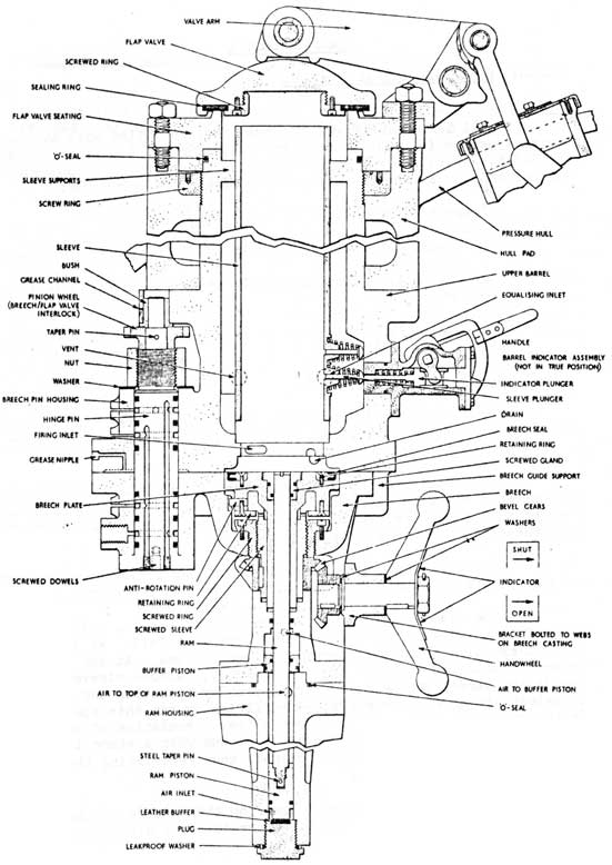
12-4-02 S.S.E. MK 2-(FIG 12-32)
This ejector is designed to discharge pyrotechnics and decoys of U.K. manufacture down to Max. diving depth, silently and without giving visible indication on the surface.
The primary method of discharge was originally intended to be by air operated ram with air "bubble" discharge as a secondary method. At present all stores are suitable for air discharge only and therefore the ram feature is not normally used.
The air pressure in both cases is supplied by a sea operated reducer giving an output of 200 P.S.I. above sea pressure.
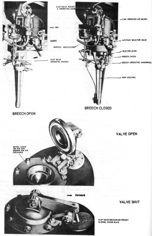
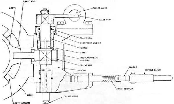
The ejector consists of a barrel with a 6 in. internal diameter which fits on a pad piece welded to the pressure full. At the outboard end a flap valve shuts the barrel off from the sea. At the inboard end is the breech to which is attached the ram assembly. A loose sleeve of 4 in. bore inside the barrel can be raised or lowered by operating the selector valve to select air or ram discharge. When firing by ram this sleeve is positioned in the raised position. This allows a free circulation of water between the sleeve and the barrel to prevent a vacuum when a store is discharged. For air discharge the sleeve is lowered, thus restricting the firing air to the inside of the sleeve.
A plunger operated by a lever on the outside of the barrel gives an indication of whether or not the store has been discharged.
12-66
Fig. 12-32
SSE. MK. 2
GENERAL ASSEMBLY
12-67
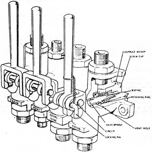
12-4-03 S.S.E. MK 2 ASSEMBLY-(FIG 12-33)
1 MULTI VALVE UNIT
A. group of four lever-operated valves provided to flood , drain, vent and fire the ejector and positioned at least 12 in. below the breech asst'. to facilitate gravity draining.
a. Drain valve. Connected to a pipe from the lower end of the barrel.
b. Vent valve. Connected to a pipe fitted between the barrel and the sleeve with its orifice at the top of the barrel.
c. Equalizing valve. Connected between the lower end of the barrel and a hull valve. Enables the barrel to be flooded up and equalized to allow opening the flap valve.
NOTE.
The construction of the drain valve and equalizing valve operating levers is such that the vent valve is operated on the same movement.
FIG. 12-33
MULTI-VALVE UNIT
12-68
d. Firing valve. This admits air from the firing reservoir to the selector valve which is positioned for air or ram firing.
2 THE RAM
The ram housing is attached to the underside of the breech. The ram rod is positioned in the centre of the breech where it is sealed by an "O" seal. The ram rod is screwed to a piston which works inside the ram housing. Where necessary the ram is made air tight by "O" seals to prevent air escaping from the firing side to the re-cock side and vice versa. A buffer piston is fitted at the top of the ram piston bore to retard the ram movement and to suppress noise. A leather pad is fitted at the bottom of the ram bore to cushion the piston on the re-cock cycle and to prevent noise.
3 THE BREECH
The breech moves horizontally and is pivoted on a hinge Tin secured in a cast projection on the side of the barrel. The breech pin is secured to the breech casting and pivots when the breech is moved. The air supply for operating the ram is channelled through ports in the breech pin which are lined-up only when the breech is properly shut. This ensures that the ram cannot be operated accidentally when the breech is open.
A spring loaded locating pin on the side of the breech mates with a hole in the barrel casting and ensures the breech is properly aligned when shut. The pin is removed by a lever to free the breech for opening.
In the centre of the breech plate is a short sleeve which is moved up or down by a gear and handwheel assembly. This sleeve is moved upward against the bottom of the barrel to form a seal when the breech is shut, and moved downward to release the breech for opening. Around the outer edge of the sleeve is a neoprene seal that forms a watertight joint when the sleeve is forced against the bottom of the barrel.
4 FLAP VALVE-(FIG 12-35)
A cast-steel dish-shaped cap with a neoprene seal secured to its inside perimeter mates with the top of the barrel and is referred to as the flap valve. This flap valve is operated by a gear and link mechanism interlocked with the breech to prevent both from being opened at the same time. The flap valve operating gear is constructed to allow any excess pressure in the barrel to escape when the flap is shut. The flap valve operating mechanism is fitted with a remote shutting release to shut the flap in the event that the operator cannot use the normal method.
12-69
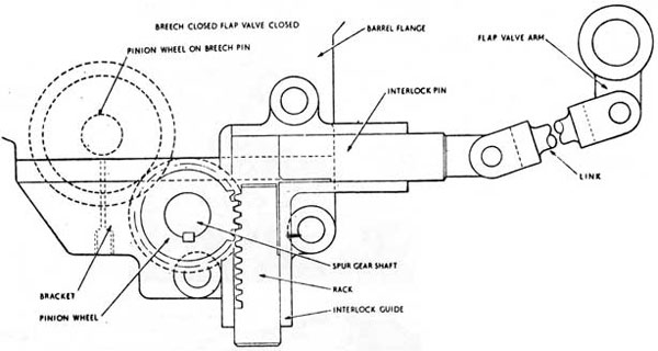
5 INTERLOCKS
a. Cam operated interlock valves. Two poppet valves operated by the flap valve operating mechanism. One of the valves ensures that air cannot be supplied to the firing lever until the flap valve is fully opened. The other valve opens as the flap valve is shutting and supplies air to ensure that the ram is returned to the housed position before the flap valve is fully shut and the breech free to open.
b. Mechanical interlock between the breech and the flap valve permitting only one to be opened at a time.
c. Breech hinge pin air ports. These ports supply air for operating the ram only when the breech is fully shut.
Fig. 12-34
Breech/Flap Valve Interlock
12-70
FIG.12-35
SSE. MK.2
BREECH & FLAP VALVE
12-71
12-4-04 OPERATION OF S.S.E. MK 2
1 PROCEDURE FOR FIRING BY AIR.
a. LOADING.
i. Move selector valve handle to the AIR Position
ii. Charge the firing reservoir
iii. Check ejector drained down.
iv. Open the breech and inspect the bore.
v. Insert the pyrotechnic
vi. Shut the breech, ensure that the locking pin
vii. is engaged, screw the breech seal up tight.
viii. Check the Equalizing Hull valve open. (Should be opened during Opening up for Diving).
ix. Open the Equalizing valve on the Multi valve unit, until a full bore of water comes from the vent, then shut.
x. Report, "Forward S.S.E. loaded with a ______.
b. FIRE
At the order "Fire the Forward S.S.E.", repeat the order and;
i. Open the flap valve
ii. Pull the firing valve
iii. Operate the indicator plunger to check that the store has been discharged.
iv. Report "Forward S.S.E. fired".
c. DRAINING DOWN
i. Shut the flap valve
ii. Move selector valve handle to RAM position and operate the drain/vent handlever.
iii. When drained down, open the breech, remove the pyrotechnic baseplate and then inspect that the bore is clear.
iv. Report "Forward S.S.E. drained down, bore sighted clear."
NOTE
The baseplate on most pyrotechnics are fastened to the body by small lead sheer pins. When the pyro is fired the lead pins shear off allowing the pyro to float clear. Small bits of lead from these shear pins accumulate on the breech plate and in the breech area causing leaks during flooding-up operations. Care should be taken to ensure that these bits of lead are removed after firing.
12-72
2 FIRING BY RAM- (FIG 12-36)
a. LOADING
i. Move selector valve handle to RAM position.
ii. Charge firing reservoir.
iii. Check ejector drained down.
iv. Open the breech, check the bore clear.
v. Insert the pyrotechnic. Ensure that it is a type suitable for RAM discharge.
vi. Shut the breech, ensure locking pin engaged.
vii. Operate the equalizing/vent handlever. When equalized open the flap valve.
b. FIRING
i. Pull the firing lever, listen for the ram.
ii. Operate the indicator plunger and ensure that the pyrotechnic has been fired.
iii. Shut the flap and listen for the ram to return.
iv. Drain down.
NOTE
Observe the same reporting procedure on RAM as used for AIR firing.
FIG. 12-36
SELECTOR ASSEMBLY
12-73
12-4-05 S.S.E. MK 4
The S.S.E. MX 4 is fitted in the ATR of all Canadian "O" class submarines. The model fitted is the MX 4 1B.
This S.S.E. is designed to eject stores by sea-water forced into the barrel by an air-pressure operated water-ram. This method of firing is called "Water-Ram Discharge" and has several advantages over the air impulse method. The Mk 4 can eject stores down to any depth at which the submarine can operate and does not make any indication on the surface such as bubbles. Both U.S. and U.K. manufactured pyrotechnic and countermeasure stores can be discharged. As U.S. stores are 1 in. less in diameter than the bore, a fiberglass (GRP) sleeve is provided for lining the barrel to allow these smaller diameter stores to be used. The barrel is long enough to accommodate any store presently supplied for use in. C.F. submarines.
The MX 4 S.S.E. is shock tested and would be retained aboard in wartime, whereas the MK 2 is not and would have to be landed.
12-4-06 S.S.E. MK 4 ASSEMBLIES.
The S.S.E. MK 4 1B consists of several major assemblies, these are;
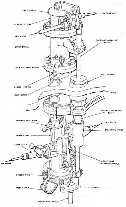
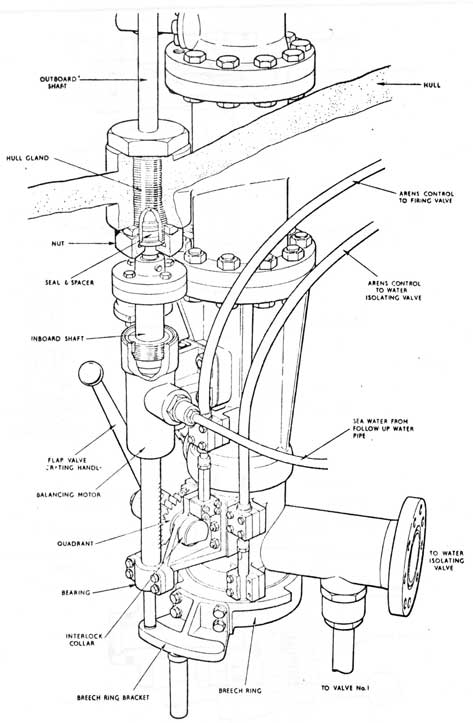
1 THE BARREL ASSEMBLY-(FIG 12-37)
a. Inner barrel, centre section, outer barrel.
b. Breech assembly including breech ring, breech door, operating handle and bracket.
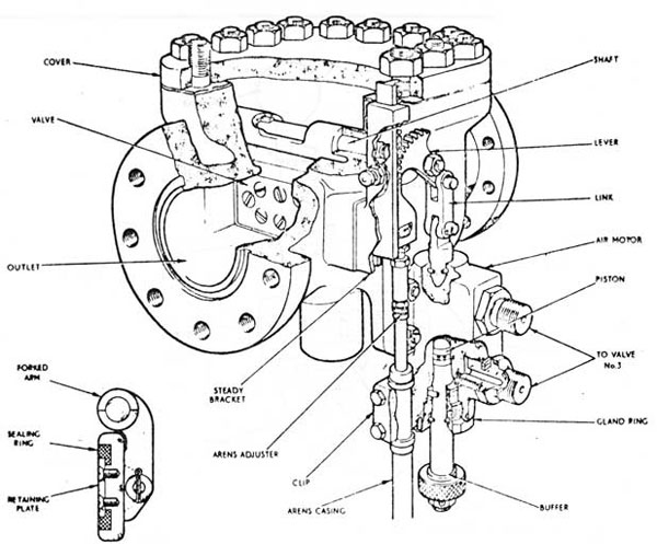
c. Flap valve, operating handle, operating shafting and linkage.
d. Upper and lower indicators, hull gland and shafting. (FIG 12-40)
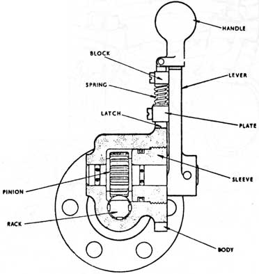
e. Sleeve catch. (FIG 12-41)
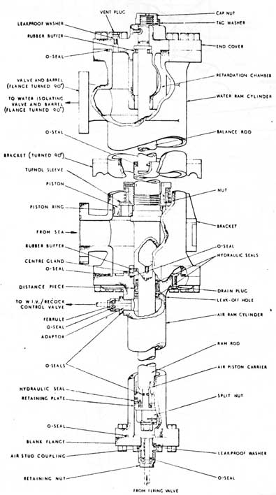
2 AIR-WATER RAM ASSEMBLY-(FIG 12-38)
a. Air-reservoir
b. Air ram
c. Water ram
d. Air and water ram housing
e. Water isolating valve -(FIG 12-43)
12-74
Fig. 12-37
Ejector Barrel Assembly
12-75
FIG. 12-38
AIR/WATER RAM ASSEMBLY
12-76
Fig 12-39
Main Valves
12-77
FIG. 12-40
INDICATORS
12-78
Fig. 12-42
Flap Valve Operating Gear and Interlocks
12-79
FIG. 12-41
Sleeve catch
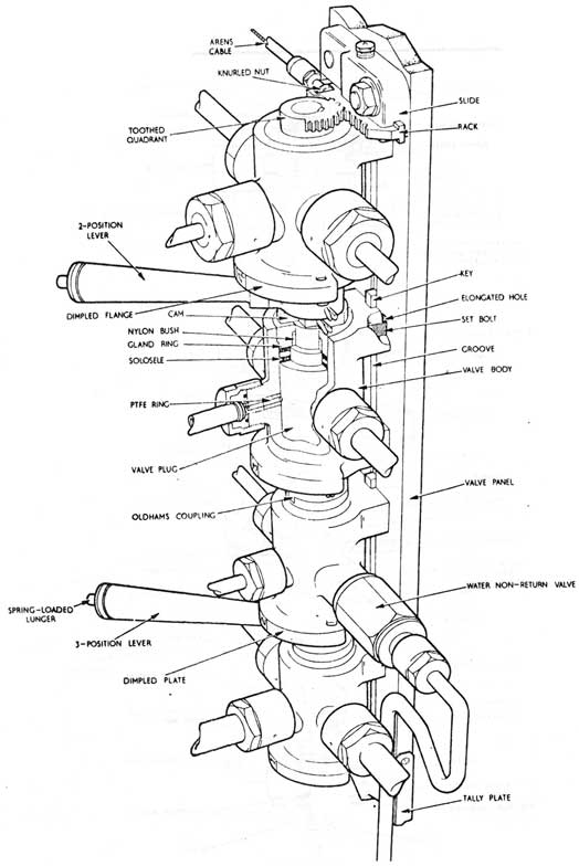
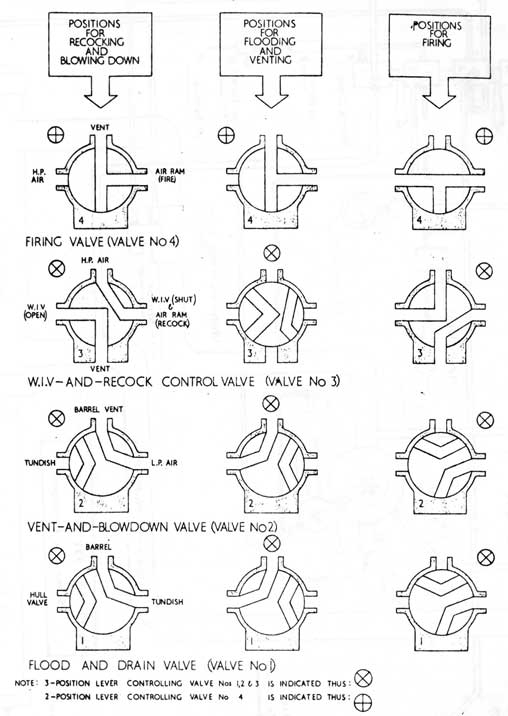
3 MAIN VALVE UNIT- (FIG. 12-39)
a. Valve panel
b. Valve No. 1, flood and drain valve
c. Valve No 2, vent and blow down valve
d. Valve No 3, water-isolating-valve and recock-control-valve
e. Valve No 4, firing control valve
f. Operating handle for valves 1, 2, and 3 and operating handle for valve 4.
g. quick acting stop valve, (blowdown valve)
h. Misfire stop valve
j. Water non return valve
12-80
Fig. 12-43 Water Isolating Valve
4 INTERLOCKS-(FIG 12-42)
Several interlocks are incorporated into the S.S.E. MK 4 13
to ensure safe operation. These are:
a. An interlock between the flap valve and breech to prevent both being opened at the same time.
b. Breech and water isolating valve interlock, provided to prevent both from being opened at the same time.
c. Breech ring lock: prevents the breech ring from moving when the breech door is opened.
12-81
d. Firing valve - flap valve interlock. Prevents the firing valve (No 4) from being moved until the flap valve is fully open, and prevents the flap valve from being shut when valve No 4 is in the "fired" position.
e. A cam is fitted to the top of valve No 3 to prevent the firing valve from moving until valves 1, 2 and 3 are in the correct position for firing. This cam also prevents operation of valves 1, 2 and 3 until valve No 4 has been replaced after firing.
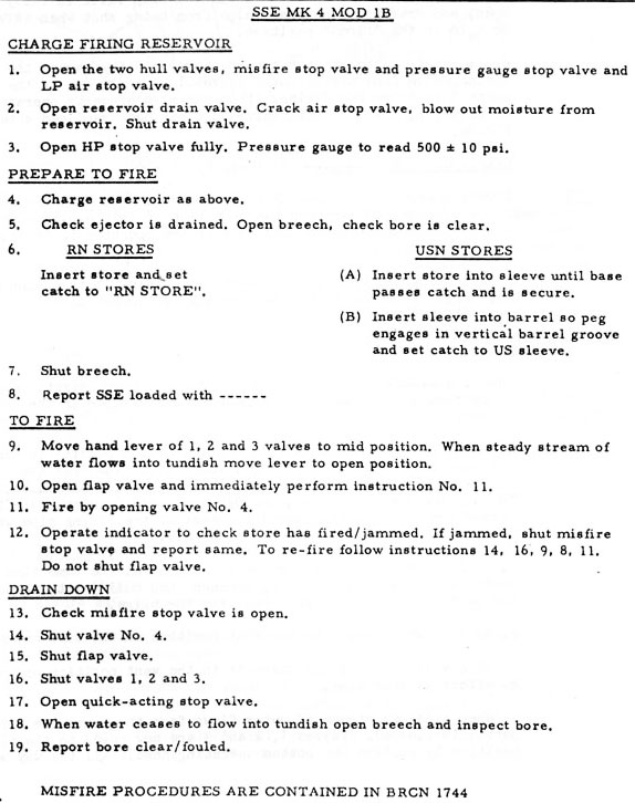
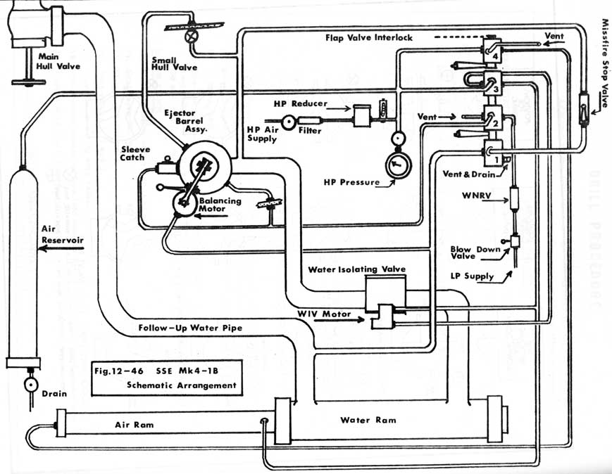
12-4-07 OPERATION OF THE S.S.E.-(FIG 12-44 FIG 12-46)
NOTE Always operate the S.S.E. MK 4 in accordance with the instructions posted near the ejector. Never rush the operation of this S.S.E. except in the case of an extreme emergency and only if the operator is thoroughly familiar with its operation.
For studying the operations described in these instructions use BRCN 1744(2), "Drill Procedure", FIG 1-10(Main Valve Connections) and FIG 1-14, General arrangement.
1 FLOODING UP.
Load the S.S.E. by carrying out steps one through eight. When
step nine is carried out the S.S.E. is flooded and equalized in the following manner:
a. Move the handle of Valves 1, 2 and 3(bottom handle) to the mid position. When this is done; water will flow from the follow-up water pipe, through the branch pipe to No 1 valve, through the now open valve, through the normally open Miss-fire stop-valve and into the barrel by means of the firing pipe which is isolated from the water ram by the WIV.
b. No 2 valve is moved to the vent position at the same time and vents the barrel from the top, through the hull joint, through the vent ports of valve No 2 and into the bilge.
c. No 3 valve is moved to the shut position on the same movement.
No 4 valve, the firing valve is in the vent position and has no effect at this time.
d. When a steady stream of water flows from the vent pipe the barrel is flooded. Valves 1, 2 and 3 are now moved to the firing position by pulling the bottom operating handle all the way across.
12-82
DRILL PROCEDURE
FIG. 12-44
Adjacent to the SSE Mk 4 in the submarine, the following notice
is displayed giving information for the guidance of operating personnel:
12-83
FIG. 12-45
MAIN VALVE CONNECTIONS
12-84
12-85
2 FIRE POSITION
When the valves, 1, 2 and 3 are moved all the way across:
a. Open the flap valve immediately.
b. Valves 1 and 2 are shut
c. Valve No 3 vents the shutting side of the WIV motor to
atmosphere and its other two ports supply air to the opening side of the WIV motor causing the WIV to open. When the WIV opens a link and Arens cable arrangement inserts a lock bolt into the breech ring preventing it from being moved. (WIV-breech interlock).
d. Once the WIV is open the firing valve, No 4, may be operated.
e. To fire, valve co 4 is pulled all the way over to the open position. The valve will admit air from the reservoir to the firing side of the air ram, thus starting the firing stroke. Also, when No 4 valve is operated a toothed quadrant-rack and Arens cable arrangement will insert an interlock bolt into the flap valve operating handle collar thus locking the flap valve open while firing.
When the air-ram begins its stroke so does the water-ram as they are constructed on a common shaft. Movement of the water-ram forces a column of water from the ram housing, through the connecting pipe and the open WIV, into the barrel forcing the store out through the open flap valve. The space created in the water ram housing behind the ram is filled with water entering through the main valve and follow-up water pipe preventing a vacuum from forming during the firing stroke.
NOTE The recocking side of the air-ram is vented to atmosphere through
No 3 valve and the piping of the shutting side of the WIV motor. The vent port is located in the back of valve No 3 as shown in FIGS 12-45 and 12-39 and has no pipe attached to it.
f. When the rams have completed the firing stroke, i.e. "fired", operate the indicator plungers to ensure that the store has cleared the barrel. If necessary carry out the misfire drill as outlined in the Drill Procedure.
Assuming the store has cleared the barrel, shut No 4 valve. This will withdraw the flap valve interlock allowing the flap valve to be shut. In the shut position No 4 valve will vent the firing side of the air-ram to allow it to be recocked.
12-86
3 RECOCKING AND BLOWING DOWN
a. Shut the flap valve. After steps 14 and 15 have been completed;
b. Move the operating handle of valves 1, 2 and 3 all the way back to the "shut" position.
Valve No 1 will drain the barrel
Valve No 2 will allow air from the "quick Acting Stop Valve" to pass through the water non-return valve, valve No 2 and into the barrel via the venting pipe. Opening the Q.A. stop valve (step 17) will put a low pressure blow into the barrel and force the water out through valve No 1 and into the bilge.
Valve No 3 will now vent the opening side of the 417 motor to atmosphere through one pair of forts. The other pair of ports will supply H.P. air to the shutting side of the WIV and, by means of a branch pipe supply H.P. air to the recocking side of the air ram. The air/water ram will recock, the WIV will shut and remove the interlock from the breech ring.
c. After steps 13 through 19 have been carried out, the S.S.E. is again ready for loading.
12-4-08 S.S.E. AK 7-(FIG 12-47)
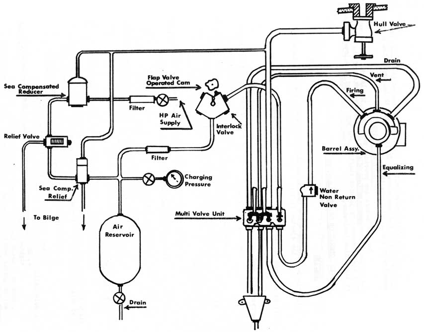
This ejector is designed to eject pyrotechnics and decoys of U.S. design down to maximum depth. The MK 7 is based on the AK 2 and utilizes many of the MK 2 components. The MK 7 uses air bubble discharge only, the air pressure being regulated by a sea operated reducer.
12-4-09 DESCRIPTION
The hull pad, flap valve and flap valve operating assemblies the Mk 2 have been retained. The barrel of the Mk 7 is bolted to the inside flange of the hull piece and extends downward approximately 3 ft. occupying the same space as the Mk 2 barrel and ram assemblies. The bore has been reduced to 3 in. and a sleeve of this dimension extends upward to the flap valve. The breech swings horizontally and is generally similar to that of the Mk 2 without the ram feature. Jointed shafting joins the breech hinge to the breech/flap valve interlock gear, identical to that found on the S.S.E. MK 2.
The flap valve operated cam and poppet valve assembly has been retained. The ram return valve has been blanked off and only the firing air supply valve is used. This valve is opened and shut with the operation of the flap valve and interrupts the firing air supply between the reservoir and handle.
12-87
Fig. 12-47
SSE MK 7
Schematic Arrangement
12-88
The Multi-valve unit is identical to that of the S.S.E. MK 2 and operates in the same manner. It is located 12 in. below the breech assembly to facilitate gravity draining.
Two indicators are provided because of the length of the barrel. One is positioned near the top, the other near the bottom of the barrel. They are connected by jointed shafting and are operated by a lever located at the bottom indicator.
12-4-10 OPERATION OF THE S.S.E. AK 7
1 LOADING
a. Check the flap valve shut and operate the drain to ensure the ejector is dry.
b. Open the breech and sight the bore clear.
c. Insert the required store.
d. Shut the breech, ensure the locking pin engaged and screw the breech up firmly.
e. Open the equalizing valve, flood and equalize the barrel.
f. Report "Forward S.S.E. loaded with a _______.
2 FIRING
a. At the order "Fire the Forward S.S.E.", repeat the order, then;
b. Open the flap valve
c. Pull the firing lever
d. Operate the indicators to ensure that the store has cleared.
e. Report "Forward S.S.E. fired".
3 DRAINING DOWN
a. Shut the flap valve
b. Operate the drain/vent valve handle.
c. When water stops flowing, shut the drain/vent valves.
d. Open the breech and sight the bore clear.
e. Shut the breech and report "Forward S.S.E. drained down, bore sighted clear".
12-89
PART 12 SECTION 5
PYROTECHNIC AND COUNTERMEASURE STORES
12-5-01 PYROTECHNIC STORES.
These stores are fired from S.S.E.s while a submarine is submerged. Both British and USN. types are currently in use. These devices produce smoke or smoke and flame and are used to:
a. Mark the position of the submarine for surface and air units during exercises.
b. Give indication of a submarine in distress or mark the position of a sunken submarine.
c. Represent simulated torpedo and missile fire from a submarine during exercises.
12-5-02 COUNTERMEASURE STORES
These stores are also fired from S.S.E.s while a submarine is submerged. Presently (1974) only USN types are in use. These devices produce a variety of noises or false target effects designed to confuse acoustic search systems.
12-5-03 BRITISH PYROTECHNICS
1 YELLOW SMOKE CANDLE MK N 6(SHALLOW YELLOW)(FIG 12-51)
Can be ejected by air or ram down to 300 ft. and emits yellow smoke for 2 1/2 to 5 minutes.
2 YELLOW SMOKE CANDLE MK N 7 (DEEP YELLOW)-(FIG 12-51)
Similar to MK N6 above and can be ejected down to 625 feet.
3 WHITE SMOKE CANDLE MK N6 (DEEP WHITE)-(FIG 12-52)
Can be ejected by air or ram down to 625 feet and gives off white smoke and a bright flame which lasts a minimum of 5 minutes. Can also be fitted with Carrier, message and fluorescein M4.
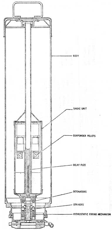
4 HYDROSTATIC ARMING DEVICE-(FIG 12-53)
The Yellow N6 and N7 and White N6 candles are all fitted with a hydrostatic arming device which operates as follows;
When the candle leaves the ejector the lead shear pins shear, leaving the base plate in the ejector. Seawater pressure acting on the diaphragm in the firing mechanism prevents the strikers, from going forward.
12-90
When the candle is approximately 30 ft. from the surface, the spring loaded plunger overcomes the sea pressure and moves forward allowing the ball bearings to fall, thus releasing the spring loaded strikers which move forward, and fire the detonators. The flash from the detonators ignites the primed cambric which in turn ignites the delay fuse in the smoke unit. The delay fuse ensures that the candle has time to steady on the surface before the ignition of the main pyrotechnic composition. The gunpowder blows the supporting disc fitted in the nozzles of the N6 and N7 yellow and the stick in the N6 yellow out through a thin diaphragm in the nose to allow the smoke and flame, as appropriate to escape.
The F.S.S. MK2, MK N3 and MK N4 all use the same arming device except as follows:
The flash from the detonators fires the gunpowder pellets at each end of the "S" shaped fuse. The fuse takes about ten seconds to burn
allowing the FSS to steady on the surface. The fuse then ignites the central pellet which fires the propellant charge in the base of the grenade cup. The grenade signal flare is thus projected out of the tube, breaking through the seal at the top of the tube and is ignited at the same time.
5 WHITE SMOKE CANDLE MK 4-(FIG 12-54
Designed to be ejected by air only down to 300 ft. maximum, it gives off white smoke, displays a bright flame and normally burns for about 15 minutes.
The MK 4 candle is a chemically reactive type with a calcium phosphide filling which, on mixing with seawater, produces phosphine gas. This gas ignites on contact with air giving a bright flame and heavy white smoke.
Firing the S.S.E. pushes the candle up the barrel breaking the brass plug free leaving the plug attached to its base plate in the breech On reaching the surface the candle turns upside down allowing seawater to enter through the ruptured sealing disc. The seawater mixes with the calcium phosphide filling causing the chemical reaction to take place.
6 FLOAT SIGNAL SUBMERGED.(F.S.S.)- (FIG 12-55, 56, 57)
An F.S.S. is a device released from a submerged submarine which, on reaching the surface, ejects a grenade signal flare into the air.
The functioning of all F.S.S.s is identical, the only differences being the depth they are designed to be released from and the type of grenade employed. The functioning of the FSS arming is discussed under HYDROSTATIC arming device.
12-91
6 Continued...)
Three types of F.S.S. are in use:
a. F.S.S. MK 2 - 300 ft. all grenades
b. F.S.S. MK 3 - 625 ft. all grenades
c. F.S.S. MK 4 - 625 ft. fluorescein dye container
Three types of No 65 grenade signals may be fitted into F.S.S. MK 2 or MK 3, these are:
a. Red - emergency only
b. Green - normally used to indicate a simulated torpedo attack.
c. Yellow - used to indicate missile firings or other prearranged exercise event.
The F.S.S. MK N4 is an emergency store and is used to mark the position of a submarine in distress.
Instead of a grenade, a plastic container of fluorescein dye is fitted in the discharge cup. At the top of the tube a cutter is arranged so that the dye container is split open on being ejected.
7 CARRIER, MESSAGE AND FLUORESCEIN M4-(FIG 12-58
This is an emergency store and is designed to be fitted to the
white smoke-candle MK N 6. It consists of a message carrier and a fluorescein dye box.
The message carrier is a 1/2 in. diameter metal tube sealed at one end capped at the other by a screwed plug. A message, written in pencil, on paper, is rolled up, inserted in the tube and sealed with the screwed cap. This provides a means of getting information from a submarine in distress to surface units.
The message carrier is fixed to a circular dye box containing fluorescein dye powder. The dye box has a perforated edge which is sealed by tape until ready for use when the tape must be removed to allow the unit to be fitted in the top of a deep white MK N 6.
12-92
12-5-04 PYROTECHNIC SAFETY PRECAUTIONS
Type of Store
Filling
Action in event of Accidental Firing on loading
Action in event of Accidental Firing in a compt: and gun cannot be loaded immediately
Firefighting equipment Required
Candle Smoke White Mark 4
Calcium Phosphide
Keep dry in secure dry stowage
Keep in secure dry stowage and ditch as soon as convenient
NIL
Candle Smoke White Mk. N6
Red Phosphorous
Load and Fire
Turn face away from candle. Remove metal nose cap. Place nose downwards in bucket. Douse with water but avoid splashes and spillage.
Water or Ansul
Candle Smoke Yellow Mk N6
Smoke Composition
Load and Fire
Remove metal nose cap. Keep pointed away from personnel for approx. 30 secs. until a stick is blown out from top. Cover with foam to absorb smoke or smother using a wet blanket.
Ansul
Candle Smoke Yellow Mk N7
Smoke Composition
Load and Fire
Remove metal nose cap and place nose downwards in bucket (there is no stick) and cover.
Ansul
12-93
PYROTECHNIC SAFETY PRECAUTIONS (CONTINUED...)
Type of Store
Filling
Action in event of Accidental Firing on loading
Action in event of Accidental Firing in a compt: and gun cannot be loaded immediately
Evacuate compt: until after the grenade has been heard to fire. Grenade itself cannot be extinguished. Cover with asbestos blanket and spray any combustible materials within vicinity with water
Asbestos Blanket Ansul
Float Signal Fluoresein Mk.N.4
Liquid Fluorescein Explosive Charge
Load and Fire
Evacuate compt. until after the fluorescein container has been heard to fire
NIL
12-94
FIG. 12-51
YELLOW SMOKE CANDLE
MK. N6
12-95
FIG. 12-52
WHITE SMOKE CANDLE
12-96
FIG. 12-53
HYDROSTATIC ARMING DEVICE
12-97
FIG. 12-54
WHITE SMOKE CANDLE MK. 4
12-98
FIG. 12-55
FLOAT SIGNAL SUBMERGED MK. 2
12-99
FIG. 12-56
FLOAT SIGNAL SUBMERGED MK. N3
12-100
FIG. 12-57
MARINE LOCATION MARKER MK N4
12-101
FIG. 12-58
CARRIER MESSAGE AND FLOURESCIENE
12-102
12-5-05 U.S.N. PYROTECHNICS
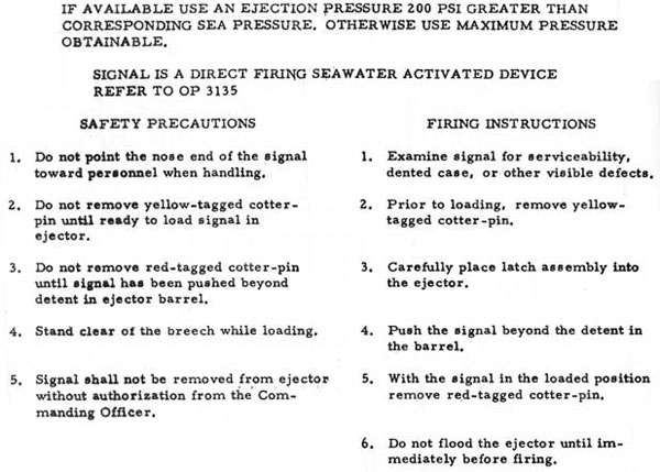
1 SUBMARINE SMOKE AND ILLUMINATION SIGNALS-MK. 66 67 AND 68 MODS 0
a. General
Submarine Smoke and Illumination Signal Mk 66, 67 and 68 are launched from a submerged submarine and are propelled into the air to a height of approximately 400 ft where they produce a parachute - suspended red, green, or yellow smoke and star display, any kind of signaling between the submarine and surface or air units.
b. Description
The signal, Figure 12-59 consists of an aluminum tube approximately 36 in. long and 3 in. in diameter. The ogival nose is secure to the forward end of the tube with four shear pins and is sealed with an "O" ring. The base of the tube is crimped to a hydrostatic fuse assembly. In the tube immediately above the fuse is located a propellant charge of black powder, a delay composition, expellant charge, starter mix for the flare composition with parachute, and starter mix for the smoke composition with parachute, in that order.
c. FUNCTIONAL DESCRIPTION
When the signal is launched, the latch rides in the groove of the ejector and is tripped part way along the barrel (or sleeve). This frees the guide shoe which is raised by the outer valve spring. When the signal clears the ejector its movement through the water rotates the guide shoe to the rear, opening the shunt between the batteries and the squibs. Pressure at depth holds the battery cavity valve shut. At a depth of 5 to 6 ft. below the surface of the water, the inner valve spring overcomes the water pressure awl unseats the battery cavity valve, thus permitting seawater to enter the cavity and energize the batteries, the electrical output of which ignites the squibs. Before the signal is loaded into the ejector and during its travel in the ejector barrel, the guide shoe serves to hold the shunt across the electrical circuits and secures the battery cavity against water entry. The latch in the cotter-pin locked forward position secures the guide shoe, and the safety cotter-pins prevent accidental tripping of the latch.
d. When the signal surfaces, the squibs ignite the expelling charge which ignites the delay charge and propels the upper carrier assembly to an altitude of approximately 400 ft. At this point the smoke and star compositions are ignited and expelled from the tube, where they are deployed on individual parachutes.
12-103
FIG. 12-59
Marine Smoke A illumination Mk. 66, 67, and 68.
12-104
Mk.
Display Display
Buord Assy. Dwg
NATO Stock No.
Explosive Wt (Oz)
66
Red smoke and flame
1332012
l370-00-960-0450
11.5
67
Green smoke and flame
1331987
1370-00-960-0451
11.5
68
Yellow smoke and flame
1332028
1370-00-960-0452
13.95
FIG. 12-60
12-105
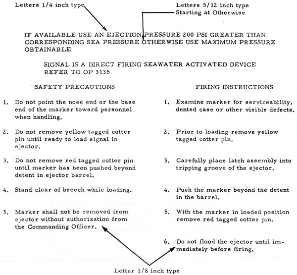
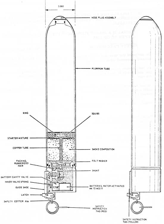
2 SUBMARINE LOCATION MARKER MK. 21, 22, 23 AND 24 MOD 0
a. General
This marker, Figure 12-61 is launched from a submerged
submarine and produces a red (Mk. 21), yellow(Mk. 22), green
(Mk. 23), or black(Mk. 24) smoke display on the surface of the water which may be used for any desired types of signalling or marking purposes.
b. Description
The marker consists of a cylindrical aluminum tube approximately 3 in. in diameter and 18 1/4 in. in length, its forward end is fitted with a nose plug and a hydrostatic fuse assembly is fitted to the after end. The outer case is stencilled to indicate the smoke colour. Net explosive weight is 9.68 ozs.
c. Functional Description
When the marker is launched, the latch rider in the groove of ejector and is tripped part way along the barrel (or sleeve). This frees the guide shoe which is raised by the outer valve spring. When the marker clears the ejector, its movement through the water rotates the guide shoe to the rear, opening the shunt between the batteries and the squibs. Pressure at depth holds the battery cavity valve shut. At a depth of 5 to 6 ft. below the surface of the Ovate the inner valve spring overcomes the water pressure and unseats the valve, thus permitting seawater to enter the cavity and energize the batteries, the electrical output of which ignites the squibs. Before the marker is loaded into the ejector, the guide shoe serves to hold the shunt across the electrical circuits and secures the battery cavity against water entry. The latch in its cotter-pin-locked forward position, secures the guide shoe and the safety cotter-pins prevent accidental tripping of the latch.
d. After the marker reaches the surface of the water, current from the battery fires the squibs which ignite the starter mixture. This in turn ignites the smoke composition, and the gases of combustion force out the nose plug, permitting the smoke to be
emitted.
e. The Safety Precautions.-(FIG 12-62)
The safety precautions outlined in AEM EO 30-510-2 shall be observed at all times during handling and storage of this marker.
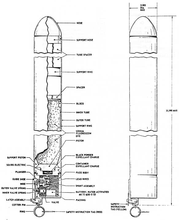
This marker, Figure 12-63 is fired from a submarine ejector and is used to indicate the position of a submerged submarine. On rising to the surface of the water it produces a persistent yellow-green fluorescent colour on the surface of the water.
b. Description
The marker consists of a cylindrical aluminum tube 35.990 in. in length. At the base end of the tube is fitted a hydrostatic fuse similar to that for the marine smoke and illumination signals, Mk. 66, 67 and 68.
Above the fluorescein dye are tube spacers and a support ring and the tube is sealed by an ogival-shaped nose.
12-108
FIG. 12-63
MARINE LOCATION MARKER MK. 28
12-109
c. Functioning
On ejection the device rises to the surface of the water where the squibs on firing ignite the expellant charge which separates the hydrostatic fuse from the aluminum tube and the expellant container from the piston. The piston is then free to fall away allowing the fluorescein dye to spill into the water and produce a yellow-green fluorescent colour.
4 FALSE TARGET, SUBMARINE, MK. 2 MODS 0 AND 1
a. General
The devices described here-in are designed expressly to confuse and disrupt enemy underwater echo ranging by producing, through chemical action, a large cloud of finely divided hydrogen bubbles which return an echo of the same order of magnitude as that returned by a submarine.
b. Description
Each model of this device, shown in Figure 12-64, consists of a cylindrical sheet steel tube, sealed at both ends, containing a lithium hydride-paraffin mixture in separately-cupped increments. Mod 0 is approximately 19.3 in. long and 3.2 in. in diameter; it contains nine increments. Mod 1 is the same diameter but its length is approximately 36 in. and it contains 18 increments of the lithium hydride-paraffin mixture, The cups are separated by aluminum discs and there is a lead weight in the bottom of each CUD to control its attitude in the water after launching from the submarine ejector. A 1 in. metal spacer separates the base of the bottom cup from the end cap of the outer tube, and a coil spring separates the top cup from the end cap on the opposite end.
c. Instructions for Use
The following steps are taken in ejecting this device:
NOTE
This device may be launched either by air pressure or water ram. Because a false target is normally used only after it has been determined that the enemy has made contact, silent operation is highly desirable. For this reason water ramming is recommended the method of launch.
i. Lay the can on a horizontal surface to prevent spilling its inner cups when the end caps are removed.
ii. Pull off the two tear strips and remove both end caps.
iii. Remove the metal spacer and the coil springy from their respective positions within the cal.
iv. Holding the bottom cup with the thumb of one hand to Prevent it slipping out of the can, insert the top end (the end from which the coil spring was removed) into the breech of the
ejector for a distance of approximately 1 in.
v. Place a rammer against the base of the bottom cup and push all of the cups from the can into the ejector until the spring-loaded detent in the ejector drops behind the last cup.
vi. Remove the empty can from the ejector breech.
vii. Close and secure the breech door and flood the ejector barrel.
viii. Open the flap valve immediately and operate the ejector.
WARNING
When the lithium hydride contents of this device come in contact with water, hydrogen is generated almost immediately and in large volume. The flap valve of the ejector must be opened quickly, preferably within 20 seconds after pressure in the ejector barrel is equalized with area pressure. Any delay in opening the flap Vv. will build up an undesirable pressure in the ejector.
ix. Drain the ejector barrel, open the breech door, and reload another submarine false target, if desired, following paragraphs iv. through viii. above. If no further launching is intended, secure the ejector.
WARNING
If the lithium hydride-containing cups of this device are placed in an ejector barrel and are not, for any reason, launched, the flap valve or the water-flooding valve must be opened and kept open for at least 30 minutes before the breech door is opened.
d. The outer case of this device constitutes a waterproof package until the tear strips are pulled. Because the lithium hydride mixture in the cups reacts with water to produce large quantities of hydrogen gas, care must be taken to protect the watertight integrity of the outer case during all handling and storage operations Stowage should be as cool and dry as conditions permit. This device must be stowed apart from any burning or explosive devices such as pyrotechnics and ammunition. If either one or both of the tear strips has been to any degree ruptured, this device must not be kept in or returned to stowage. Instead, it must be placed in an airtight container and kept carefully and completely away from water until conditions permit disposal by throwing over the side.
12-112
WARNING
Hydrogen is explosively combustible in a confined space. Every effort must be exerted to avoid puncturing the outer tube of this device so that water might come in contact with its contents. Tear string SHALL NOT be disturbed until immediately before loading the cups into the ejector.
e. The following special safety precautions are particularly applicable to this device and must be observed.
i. The lithium hydride used with this device releases large volumes of hydrogen gas in the presence of water. The outer case ii1UST NOT LE OPENED until immediately prior to use.
ii. This device rust be carefully protected from water after the tear strips have been removed.
iii. This device must not be thrown, or rolled, or otherwise handled in a rough or careless manner since such treatment could easily destroy its watertight integrity.
iv. Opened cans must be very carefully guarded from all possibility of water contact until they can be appropriately disposed of.
f. FIREFIGHTING
Fires in the vicinity of these devices must riot be fought with water. Sand should, if possible , be used to mother the fire. Carbon dioxide (CO2) extinguishers must not be used because CO2 produces an unfavorable reaction with lithium hydride if the outer can is ruptured.