The various pipe lines are the blood vessels of the power plant, for through them flow the vapors and liquids that are the life blood of the ship.
MATERIALS
Main Steam Line-The main steam line that conveys the steam from the boilers to the main engine is made of copper or steel, depending on the pressure and temperature to be carried. The piping is made up in sections for convenient handling, being joined usually by bolted flanges, although with modern methods a certain proportion of the joints are fusion welded.
Auxiliary Steam and Exhaust Lines are also made of copper or steel and joined together in the same manner, excepting some of the smaller sized piping, which may be joined by threaded connections.
Allowances for expansion and contraction of the piping due to temperature changes must be made, either by a slip joint or an expansion loop. Piping must also be supported by hangers at sufficient points to prevent strain on the piping.
Around the outside of all steam piping is placed asbestos insulation, usually covered with sewed canvas, to hold the heat inside the pipe line.
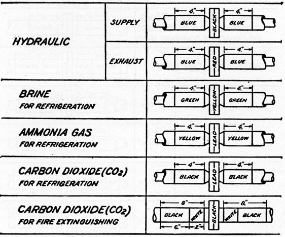
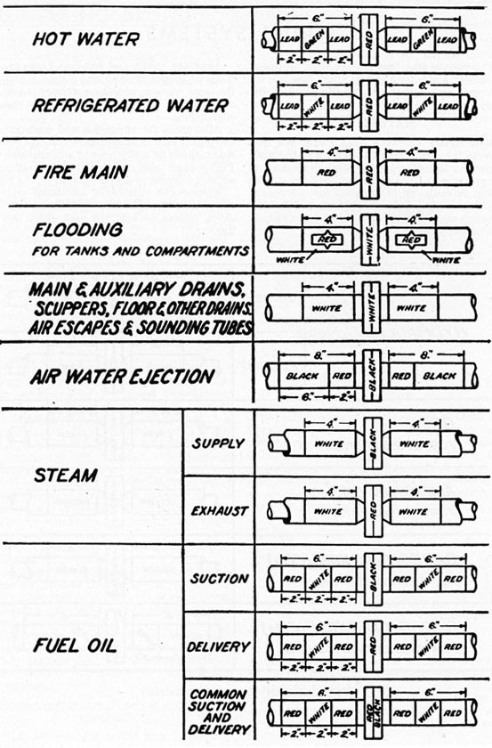
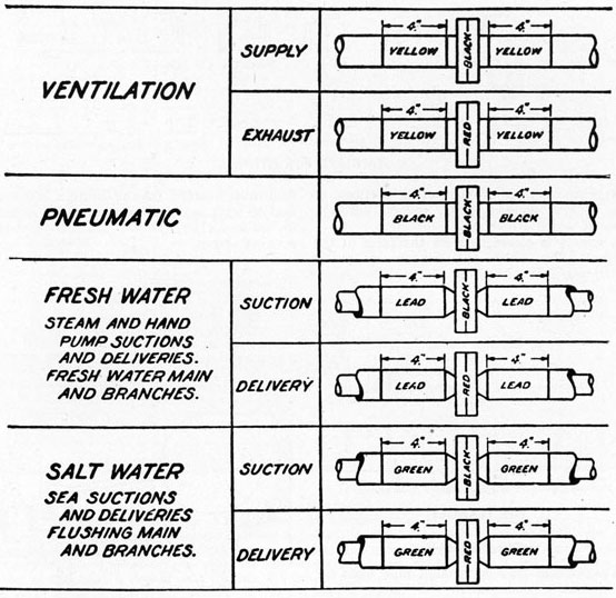
PIPE LINE IDENTIFICATION MARKINGS
108
109
Fresh Water Piping-Piping carrying fresh water should preferably be made of copper or brass to resist corrosion, although galvanized steel pipe is sometimes used.
Salt Water Service-For salt water service brass or copper piping should always be used, as corrosion is severe on steel piping.
Cold water pipes are usually covered with from 1/2 inch to 1 inch of cattle hair felt to prevent condensation forming on the outside of the pipe.
Fuel Oil and Refrigeration-For fuel oil and refrigeration, steel pipe is used.
IDENTIFICATION MARKINGS
In order that the various pipe lines carrying
different substances may be readily identified throughout the ship, a system of markings is used at intervals along the pipe lines. Some shipping companies use their own systems. The standard marking system used on most ships today is listed.
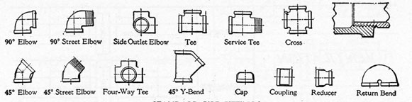
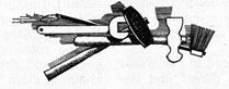
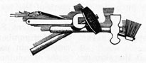
PIPE FITTINGS
Pipe is made in three wall thicknesses-standard, extra heavy, and double extra heavy. When a pipe line is installed, the straight sections of pipe must be joined together. One method is with threaded fittings of which several types are shown. The type to use depends on the combination of piping and angles to be joined. The material of the fittings should in most cases be the same as the pipe.
110
STANDARD PIPE FITTINGS
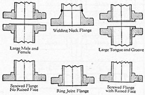
Another method of connecting sections of pipe is with flanged joints, several different types of which are shown.
A gasket is placed between the faces of the flanges, after which the flanges are pulled tightly together with bolts.
PIPE FLANGES
STEAM TRAP
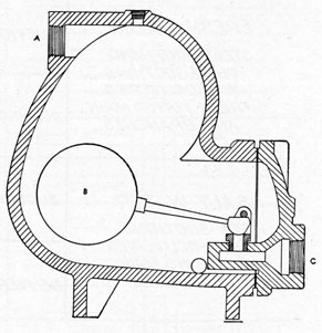
When steam travels through pipe lines for any distance, condensation will occur. When steam is admitted to a cold line, condensation is great. To automatically remove the condensate, steam traps are used.
There are several types of traps, the cross-section sketch being a trap of the float type. From a low point in the steam line a small pipe line connects to the inlet opening (A) of the trap. The condensate and steam under pressure enter the chamber. As the condensate gradually fills the chamber, the copper float (B) rises and through the float lever opens the valve. The pressure forces the condensate through the valve opening and out the discharge (C) to the hotwell. As the condensate leaves, the float drops, closing the valve before the condensate level drops below it, preventing the steam from leaving.
Steam traps are also used in the drains from
feedwater heaters, fuel oil heaters and in connection with any apparatus where it is desired to automatically remove condensate without wasting steam.
STEAM TRAP
VALVES
Valves are used to control the flow of fluids. There are many types of valves, but they are usually one of the following: globe, angle, gate, check, or cock. The working pressure and the kind of service determines the material, weight, size, and design of the valve to be used.
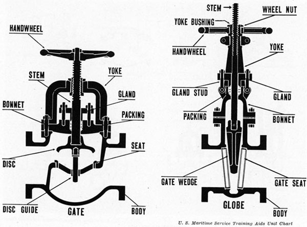
The globe valve is used to control passage of steam, water, etc. It is made up of a body, bonnet, seat and valve disc, stem, stuffing box and hand wheel. The seat may be either flat or beveled; if beveled, usually to 45°. The valve disc is fastened to the stem, which is threaded and turns in similar threads in the bonnet. The body of the valve is usually of cast steel or
111
U. S. Maritime Service Training Aids Unit Chart
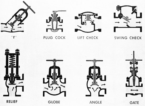
TYPES OF VALVES
The arrows indicate the direction of flow in the more common types of valves used in ship's piping. The check valves and relief valve shown are classified as automatic valves. The globe, angle and "Y" type valves are used where it is desirable to adjust the rate of flow. The gate valve should be either completely open or completely closed, otherwise chattering will result in excessive wear. The gate valve is used where a minimum amount of turbulence is desired since it offers very little resistance to flow. The gate valve shown has a rising stem which indicates at a glance whether the valve is open or closed.
brass. The valve and seat are usually of composition, and if the valve is very large it has a renewable seat, usually screwed into the body casting. On most valves, two inches and over, the threaded part of the bonnet through which the stem passes will be outside or in the form of a yoke. This keeps the threads away from the action of the steam. The yoke is part of the bonnet, the stuffing box being beneath the yoke.
The angle valve uses the same type of seat and valve disc as the globe valve, the difference being that it is used to connect pipes that meet at a right angle. The construction and materials used in the angle valve are the same as those in the globe valve, the only difference being the design. One advantage of the angle valve over the globe is that it offers less resistance to flow.
Check valves are valves that permit fluids to pass through them in one direction only, and are designed to close automatically whenever the flow of the fluid is reversed. They are made in different forms, as, vertical, horizontal and angle check valves. They are also made in swing check valves, where the valve disc is hinged and closes the seat while still at a slight angle, and globe check valves, where a globe type valve disc is provided with guides above and below the seat to keep the disc from tilting sidewise.
Adjustable check valves are of the same type generally as the globe check valve, but the. amount that the valve can lift is governed by a stem and hand wheel. These are used frequently as the feed check valve on boilers.
A cock is a valve which is capable of being
112
VALVE PARTS
quickly opened or closed. Probably the most familiar type is the pet-cock.
Blowoff valves on boilers are usually of the straightway type such as gate or "Y" valves, or of special design. Angle valves are also used for this purpose. These types of valves do not trap sediment.
Gate valves are made either as single gate valves which receive pressure on one side only, or as double gate valves, which may receive pressure on either side. Some forms of double gate valves close off the fluid passage with a solid wedge, others with a box wedge, and others with sectional gates having either parallel or wedge-shaped seats.
Gate valves are advantageous where little resistance to the flow of the liquid is desired, as they leave an unobstructed passage when fully
open. Therefore, they are largely used on water and exhaust steam connections. When throttled, that is, when only partly open, they are hard to regulate and often chatter. In all gate valves, the discs rise into the upper part of the bonnet and leave a straight passage for the flow.
One type of gate valve has the gate threaded, and the gate screws up the stem, the hand wheel remaining at the same distance from the bonnet whether the valve is open or closed. On larger gate valves a yoke is used, the stem being threaded and fitted to threads on the hand wheel. When open, the stem extends through the wheel. This type is advantageous as the threads may be properly lubricated and also do not come in contact with the steam. Gate valves should be installed in a vertical position with the hand wheel on top, if possible.
113
REFRIGERATION
On American ships fresh meat, vegetables and fruits are an everyday fare for the crew even though the ship be traveling a long distance in warm climate. This is made possible by mechanical refrigeration which keeps the meat frozen in the meat box until just before it is to be cooked. The fruits and vegetables are kept in a separate box where the temperature is kept above freezing but cold enough to preserve them until used.
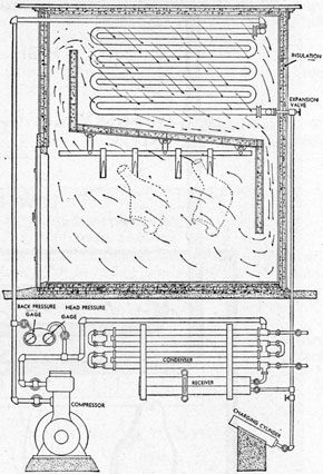
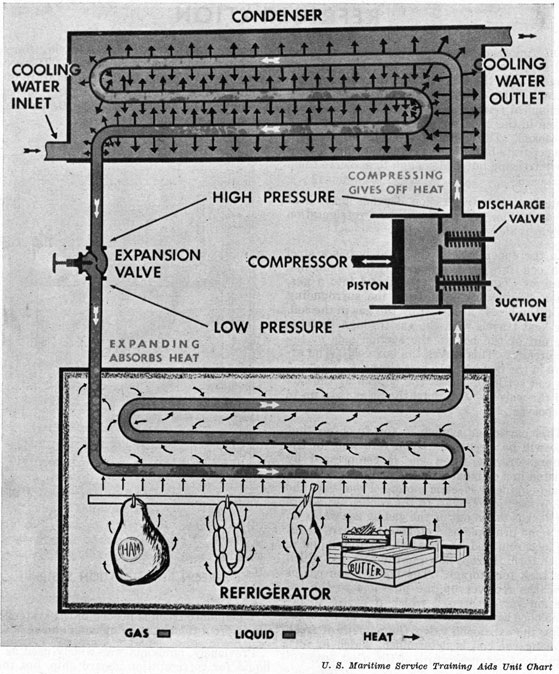
Mechanical refrigeration depends upon heat for operation. A typical modern refrigeration system is shown in the sketch.
In the upper part of the meat box is a steel pipe coil into which liquid, either ammonia, freon, or CO, is allowed to expand into a gas. When this occurs, heat from the surrounding air in the box is absorbed by the gas in the coil. The heat travels with the gas through the pipe line out of the box to the suction side of the compressor. This leaves the box cold. The arrows in the box indicate how the cold air around the coil settles down to the bottom of the box and the warmer air around the meat rises up to be cooled.
This particular system is for freon so that type will be discussed. Upon returning to the compressor, the freon gas is compressed by a piston in a cylinder which is driven by either a steam engine or electric motor. From here the compressed gas travels to the condenser, where the heat is taken out of the gas by sea water on the same principle as a steam condenser. With the heat removed, the gas returns to a liquid in which form it drops down to the receiver, which is a tank for storage. The liquid freon passes from the receiver up the pipe line to the expansion valve, through which it passes to become once again a gas in the box coil. By regulating the expansion valve, the amount of freon entering the coil is determined, which in turn regulates the temperature of the meat box.
The side walls, roof and floor of the box are insulated to keep the outside heat out and the inside cold in.
Two pressure gages are provided just above the compressor. One shows the pressure of the freon gas returning to the compressor usually around 5 to 10 pounds. The other shows
the discharge pressure of the gas leaving the compressor usually around 90 pounds. These pressures vary according to the temperature of the cooling water flowing through the condenser. The hotter the cooling water, the higher the discharge pressure and vice-versa.
FREON REFRIGERATION SYSTEM
When more freon is needed in the system it is put in from the charging cylinder shown.
Previously, ammonia was widely used as the liquid for refrigeration aboard ship, but today practically all new ships are equipped with freon systems. Freon is an odorless, harmless substance, except to the eyes upon close contact. Ammonia is highly injurious to humans, if trapped in a confined space.
When checking the refrigerating system the oiler should note the suction and discharge
114
MECHANICAL REFRIGERATION
pressures. An excessively high discharge pressure is a good indication that the cooling water to the condenser has stopped flowing. This can be serious if the pressure should continue to build up until an explosion results. Relief valves are installed as a safeguard against excess
pressure, but should not be depended upon. The oiler should definitely determine that the cooling water is flowing properly at each visit.
The oiler should check the lubrication of the compressor, and listen for any unusual sounds. Notify the engineer of anything unusual.
115
SAFETY PRECAUTIONS
Working around marine power plants, members of the crew must observe a few safety precautions if they are to escape injury.
The following rules should be thoroughly memorized and lived up to at all times:
Keep a close watch on the water level in the boilers.
Always use a torch when lighting an oil burner.
When blowing down the gage glass, look away from the glass until gage glass drain valve is closed. The glass may break and pieces fly in your eyes.
In passing up and down ladders and along gratings, keep one hand on guard rail at all times. Do not try to carry an object requiring both hands. Remember the ship may roll or pitch unexpectedly, causing you to fall to the deck or into the moving engine. The old saying, "one hand for the ship and one for yourself," is a good one.
Always use safety goggles to protect the eyes when working around flying particles, such as chipping paint or using an emery wheel. Remember you can't see with a glass eye.
When working with tools do not lay them on the gratings. The ship may roll or someone walking along the grating may accidentally kick them off, injuring the man below by striking him on the head. Put tools away when leaving the job.
When oil is spilled, wipe it up immediately. There is nothing that can cause as quick a fall as to step on an oily steel deck plate.
Always keep your arms bare and fingers free of rings when around machinery.
Never enter any kind of an empty tank or boiler until all safety precautions have been taken.
Do not smoke in unauthorized places.
Do not fool or tamper with the machinery.
Notify the engineer of any unusual occurrence, or of anything of which you are in doubt.
Keep your mind on your job.
Know where the emergency escape ladders are. Practice using these emergency ladders frequently.
REMEMBER-CONSTANT VIGILANCE IS THE PRICE OF SAFETY.
116
GLOSSARY OF ENGINE ROOM TERMS
Air Cock. A valve placed on the highest point of a boiler. Opened to allow air to escape from boiler when filling or getting up steam. Also opened to allow air to enter boiler when draining.
Air Compressor. A power-driven pump by which air is placed under pressure and usually delivered to a storage tank.
Air Ejector. The unit by which air and uncondensed gases are removed from the condenser, leaving a vacuum. Generally operated by a steam jet. Usually used with power plants having turbine-type engines.
Air Register. A part of an oil burner. By adjusting the air register the amount of air entering the furnace to mix with the oil is controlled.
Appurtenance. (Boiler)-Any equipment used with or attached to a boiler.
Auxiliary. (Auxiliary feed-auxiliary steam lines)-A duplicate, generally of smaller capacity, which can be used as a substitute or used to assist.
Atmosphere Valve. A valve by which the auxiliary exhaust steam can be released to the atmosphere instead of going to the condenser. Used in the event the condenser is inoperative such as when the ship is in drydock.
Alley Well (Tunnel Well). A deep recess at the after end of the shaft tunnel where water trickling through the stern tube collects to be pumped out by the bilge pump.
Back Pressure. The pressure of the auxiliary exhaust steam. Usually about 15 lbs. per square inch.
Auxiliary Steam Stop Valve. A stop valve placed directly on top of each boiler to cut off the flow of steam from that boiler through the auxiliary steam line.
Baffle, Gas Passage. A wall or partition of heat-resisting material between the boiler tubes to conduct the flow of gases along a definite path among the boiler tubes from the furnace to the stack.
Baffle, Water. A steel plate placed in the water and steam drum of boilers to direct and improve water circulation and prevent water splashing over into the dry pipe.
Ballast Pump. A large pump located in the engine room to transfer water ballast either from one tank to another tank, or from one tank overboard. Ballast tanks are usually filled by flooding from the sea.
Boiler. A pressure vessel used to convert water to steam by applying heat. General types: Fire-tube or Scotch boiler in which water surrounds tubes and firebox. Watertube in which water is carried in tubes which are surrounded by hot gases.
Blowdown. The difference, in lbs. per square inch, between the pressure at which a safety valve opens and the pressure at which the valve reseats, generally expressed as a percentage of the lifting pressure.
Blowdown Ring. A notched ring held in place by a setscrew which extends through the safety valve body. The amount of blowdown can be adjusted by this ring:
turn ring right-raises it and shortens blow-down.
turn ring left-lowers it and lengthens blow-down.
Blow Valves. Used to remove sludge, scum, and to reduce salinity.
Bottom blow-A valve used for blowing sludge, mud, scale etc. from the lowest portion of the boiler.
Surface blow-(Not required where pressure exceeds 350 lbs. per square inch.) Attached at normal water level of boiler to a pipe or pan which collects scum, grease etc. Used for blowing scum or grease from surface of water.
Blower. A power-driven fan by which air is supplied, under a slight pressure, to a furnace.
Bulkhead. A wall or partition on a ship; may or may not be watertight.
Bulkhead Deck. The deck which connects to any watertight bulkhead forming a watertight compartment.
Brickwork. The brick lining of a furnace made up of firebrick, refractory and insulating material forming walls which add to the efficiency of furnace operation.
Bulkhead Stop Valve. A valve located on the engine room side of the bulkhead separating engine and fireroom. Used to control flow of steam in main line.
Bilge. That portion of a ship's compartment between hull plates and floor plates or between tank tops and floor plates.
Bilge Pump. Any pump having the necessary connections to bilges and water bottoms (suction strainer, pipes, mudboxes, basket strainers, manifold etc.) may be attached directly to air
117
pump beam of the main engine or may be an independently powered pump such as the sanitary, ballast, general service or fire pump.
Circulating Pump, Condenser. A pump of large capacity used for the purpose of pumping sea water through the tubes of the condenser, thus cooling the tubes so that the exhaust steam will be condensed. This sudden reduction of volume creates a vacuum which reduces back pressure.
Combustion Chamber. A large space provided in a boiler to allow room for complete combustion to take place. Generally found in Scotch boilers, as the furnace in a watertube boiler is usually large enough to allow for complete combustion.
Condensate. This is the name given to condensed exhaust steam; it is distilled water. Condenser, Steam. A unit in which the exhaust steam from the power plant is condensed into water so as to perform two purposes: First, it reduces the back pressure on the machinery, and second, it makes possible the use of the water over again as feedwater.
Crown Sheet, Boiler. The top sheet of the combustion chamber. Usually found in marine installations using Scotch boilers.
Dampers, Uptake. A pivoted metal plate placed in the uptake or stack of a boiler for regulating draft or closing the stack or uptake. In boilers using oil for fuel, dampers are secured in the open position while the boilers are in use.
Desuperheaters, Steam. A unit by which the superheat is removed from the steam, generally consisting of a series of pipes submerged in the water in the boiler drum through which the superheated steam passes. Desuperheaters are used to protect superheaters by maintaining circulation. Also to supply steam to auxiliaries.
Draft, Stack. The flow of the hot gases from the boiler and the flow of air into the furnaces. NATURAL DRAFT is the natural flow of the cooler air into the furnaces without the aid of any mechanism; FORCED DRAFT is when the air is forced into the furnaces under a slight pressure; and INDUCED DRAFT is when the pressure in the stack is reduced to speed up the flow of air.
Dry Pipe. A perforated pipe running lengthwise in the top of the steam space of the boiler through which the steam must pass before leaving the boiler. The steam in passing through the small holes in the pipe loses most of its moisture particles which otherwise would be carried over from the boiler.
Economizer, Boiler. A feedwater heater located
in the boiler uptakes which receives its heat from the waste gases from the boiler as they pass on their way to the stack.
Evaporators. Units in which sea water is evaporated so as to obtain distilled water or fresh water for boiler feeding, etc.
Feed and Filter Tank. Generally referred to as the Hotwell (see Hotwell). A tank into which the condensate pump discharges the condensate and in which the feedwater passes through filtering material to remove oil and grease. The filtering material generally is made up of loofa sponges.
Feedwater Heaters. A heater through which the feedwater passes between the feed pump and the boiler in which the feedwater is heated by the heat contained in the auxiliary exhaust steam. Some of the auxiliary exhaust steam instead of flowing to the condenser, is led to the heater. BACK PRESSURE is the pressure of this exhaust steam in the feedwater heater, and is the pressure against which the auxiliary machinery must operate. The BACK PRESSURE VALVE is a valve which admits the auxiliary exhaust steam to the condenser, and is the valve by which the BACK PRESSURE can be regulated.
Feed Pumps. Pumps which take suction from the feed and filter tank or the reserve feed tanks and discharge the feedwater into the boilers under pressure above boiler pressure. Generally a vertical, simplex, double-acting, reciprocating steam pump, although some vessels now use centrifugal pumps, or electric driven triplex pumps.
Feedwater, Boiler. Water which is used to make steam in the boilers. Between the feed tank and the boiler, the water is known as FEEDWATER; between the boiler and the machinery as LIVE STEAM; between the machinery and the condenser as EXHAUST STEAM; and between the condenser and the feed tank as CONDENSATE.
FEEDLINE CHECK VALVES. Valves placed in the feedwater line just before the boiler through which the water may pass in one direction only-toward the boiler. Any flow from the boiler causes the valve to close.
Feedline Stop Valve. A valve placed between the feed check valve and the boiler, attached directly to the boiler shell to out off the flow of water in either direction. Both the feed stop and the feed check valves are required by law.
Fire Pump. A pump of large capacity for supplying sea water to the fire mains. Also has, as
118
a rule, a bilge suction connection and a ballast suction connection.
Flareback, Furnace. A dangerous explosion in a boiler furnace due to the ignition of accumulated gases from the fuel. Caused by lighting fires without a torch, leaky burners, etc. Can cause extensive damage to the boiler and result in the death of the fireroom personnel.
Floor Plates. Steel plates which form the decking of the engine room and fireroom.
Foaming, Boiler. The creation of bubbles or froth on the surface of boiler water, caused generally by impurities in the boiler water. Causes water to be carried over from the boiler into the steam lines.
Fresh Water Pump. A pump by which fresh water is delivered from the tanks to wash bowls, showers, etc., for washing purposes.
Furnace, External. A place in which the fuel is burned to produce the heat necessary to evaporate water into steam in the boiler. External furnaces are outside of the boiler shell and generally form part of the boiler setting. Most watertube boilers have external furnaces.
Furnace, Internal. A space within the boiler shell in which the fuel is burned to produce the heat necessary to evaporate water into steam in the boiler.
Fusible Plug. A safety device used in a boiler to warn the operator of dangerously low water. The plug has a hole which tapers to a small diameter and the water side taper is filled with banca tin 99.3% pure. This tin melts before low water harms the boiler. There are two types-waterside and fireside and they are named because of the way they go in. Example: Waterside plug goes in from the waterside of crown sheet or tube.
Gag, Safety Valve. A horseshoe shaped clamp for locking a safety valve closed. Used during annual Hydrostatic test, often referred to as a clamp.
Generators, Electric. Machines which generate electricity for use on shipboard, driven by some type of power unit.
Governor, Speed Control. A device by which the speed of a piece of machinery is regulated.
Handholes. Openings for cleaning boiler. When large enough to permit passage of a man are referred to as manholes. Special plates are used to seal these holes and great care must be used when closing and tightening.
Hotwell. The name sometimes given to the feed and filter tank. It is also the name given to the reservoir at the bottom of the condenser from
which the condensate pump takes its suction.
Hydrostatic Test. A test put on a boiler with water under a pressure from 11/4 to 11/2 times the safe allowable working pressure of the boiler. Put on by the boiler inspectors, and, while under this pressure, the boiler is inspected for ruptures and leaks.
Ice Machine. The name given to the compressor in the refrigerating system. Driven by some type of power unit.
Injector, Boiler Feedwater. A jet pump by which a jet of steam is used to force feedwater to the boiler. Simple in design, delicate in construction, the injector has been replaced by other types of pumps.
Lance, Hand, Air or Steam. A unit by which a jet of air or steam is directed into tubes of a boiler for removing soot. Operated by hand. Several safety precautions must be observed when using steam lance.
Manifold, Valve. A casting into which a number of pipe lines are led, each pipe opening controlled by a valve.
Main Steam Stop Valve. A valve connected directly to the top of the boiler shell which controls the flow of the steam from the boiler to the main steam line, which supplies only the steam to operate the main engines.
Manhole, Boiler. Generally an elliptical hole to allow the passage of a man's body so that the boiler can be entered for inspection, overhaul, or repairs. Covered from the inside with a plate known as a manhole cover, which is secured from the outside by dogs.
Muddrum, Boiler. A small drum or header located at the lowest point of the boiler into which sediment, sludge, and other impurities of the boiler water precipitate, and from which they are removed by the bottom blowdown valve.
Pressure Gage, Boiler. A gage by which the steam pressure in the boiler is registered. The pipe which connects this gage to the steam space of the boiler is fitted with a valve directly connected to the boiler shell.
Priming, Boiler. An action taking place in a boiler which causes water to be carried over into the steam lines.
Propeller, Screw. A device which, when rotated, causes a vessel to move through the water. Often referred to as the wheel or screw.
Reduction Gears, Speed. Due to the fact that some main engines, such as turbines, are most efficient at high speeds, and that the propeller is most efficient at fairly low speeds, the use of
119
gears to reduce speed of screw is necessary.
Refractory, Furnace. Plastic and molded heat-retarding and insulating material used mostly for furnace linings.
Reducing Valve. A valve by which a varying high steam pressure can be automatically reduced to a constant low pressure.
Retarders. Flat, twisted strips of steel usually found in the tubes of firetube boilers, feed heaters, etc. to slow down the flow of the heating agent, so that there is time for more heat to pass through the tube.
Safety Valves, Boiler. Spring loaded valves which are set to open at the safe working pressure of the boiler. Used to relieve excess pressure in the boiler so that the boiler will not explode.
Salinometer Cock. A small cock or valve by which a sample of boiler water can be taken from the boiler for test as to acidity, alkalinity, or salinity.
Sanitary Pump. A pump which delivers sea water to the "heads" for sanitary purposes.
Saturated Steam. See Steam.
Scale, Incrustation. Formations on the plates and tubes of boilers due to the impurities in the boiler water.
Skin Valve, Sea Cock. A valve at the skin or side of the vessel; generally refers to the one on the blowdown lines used to prevent sea water from backing up to the boilers.
Soot Blowers. Mechanical devices attached to the boiler casing through which a steam jet is directed against the surface for removing soot deposits.
Spring Bearings, Main Line Bearings. Those bearings which support the weight of the main propeller shaft between the thrust bearing and the stern tube. They also tend to maintain the alignment of the shaft.
Staybolts, Boiler. Solid and drilled stays which are used to support the combustion chambers in boilers.
Steam. Steam is an invisible vapor produced by the rapid evaporation of water when heat is applied. SATURATED STEAM is steam in direct contact with the water from which it was formed and has the same temperature as the water. It may contain a light amount of moisture in which case it is known as WET SATURATED STEAM, or it may be 100% dry in which case it is known as DRY SATURATED STEAM. If this steam is led to a separate unit known as a superheater, which is placed in the path of the hot gases, its temperature is
increased above that of the water from which it is formed, and it is then called SUPERHEATED STEAM.
Steam Generators. Steam generators is the name given to the combination of the boiler, superheaters, economizers, air preheaters, de-superheaters etc.
Steering Engine. Due to its large area, it is impracticable to move the rudder by hand; instead, the rudder is turned by a power-driven unit which is known as the steering engine. Stern Gland. The stern gland is a packing gland at the inside end of the stern tube which prevents excessive flow of sea water in through the stern tube. This gland should never be tightened so much that there is no trickle of water through the stern tube, except in port, because this water trickle supplies lubrication to the stern tube.
Stern Tube. The tube or bearing through which that part of the propeller shaft (tail shaft) which contains the propeller passes through the stern of the vessel, generally lined with lignum vitae.
Superheaters, Steam. Units generally consisting of a number of tubes through which saturated steam passes, and over which the hot gases of combustion of the boiler pass so that the steam may be heated to a higher temperature.
Superheated Steam. See Steam.
Surface Blow. See Blowdown Valves.
Tail Shaft. The last portion of the propeller shaft, which passes through the stern tube, and onto which the propeller is fastened.
Telltale Holes, Staybolt. Small holes drilled in the ends of staybolts so that if the staybolt breaks or cracks, the steam and water will escape through the hole to the outside of the supported space to give warning of the break.
Throttle Valve, Main Engine. The valve by which the speed of the engine may be regulated by controlling the supply of steam flowing to the engine.
Thrust Bearing, Main Shaft. A bearing on the main shaft to prevent endwise movement of the shaft, so that the thrust of the propeller is transmitted along the shaft to the thrust bearing which transfers the thrust to the hull of the vessel.
Trap, Steam. A unit for allowing passage of condensate but preventing passage of steam.
Try Cocks, Boiler Water Level. Three small valves or cocks connected directly to the boiler shell at the water level so that the accuracy of
120
the gage glass can be checked. One is located above, one at, and the other below the normal steaming water level (approximately).
Turning Gear, Jacking Gear. A unit which when engaged may be used for slow turning of the engine or preventing the engine from rolling over accidentally. Never engaged while steam is on main engine.
Uptakes, Furnace. Passages through which the gases of combustion, on leaving the boiler, are led to the stack.
Water Level Gage. A means by which the water level in the boiler is visible to the operating personnel, generally consisting of a glass tube for low pressure boilers, and a special nonshatterable glass gage for high pressure boilers.
Wet Air Pump. When the condensate and the air are both removed from the condenser by the same pump, the pump is known as a wet air pump. This system does not maintain as high a vacuum in the condenser as when the two pumps are used.