Principle-A boiler is a closed vessel in which steam is generated from water by the application of heat.
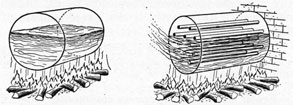
The simple boiler is like a barrel, consisting of a cylindrical steel shell, with the ends closed by flat steel heads. It is partly filled with water and then sealed, after which a fire is started beneath it. The fire and hot gases rise around the lower outside of the shell, the heat being conducted through the steel into the water. This heats the water on the bottom of the boiler first. Hot water being lighter than cold water, it rises, while the colder water in the upper part, being heavier, sinks down to replace it and is in turn heated. These are convection currents, and the process is known as circulation, which goes on continually while a boiler is in service. Circulation is good in some boilers and poor in others, depending upon the design. This is important as will be pointed out later.
The water gradually reaches the temperature where steam is given off, which accumulates in the space above the water known as the steam space. As the steam accumulates, a pressure is built up which would create a very dangerous
SIMPLE BOILER AND SIMPLE FIRETUBE BOILER
condition with the simple boiler. As pressure is exerted in every direction, the flat heads would bulge outward because a flat surface cannot support itself. The boiler would hold very little pressure and would be useless.
The first thing that has to be done with this boiler is brace the flat heads in order to keep them from being pushed out by the pressure. This is accomplished by placing heavy steel rods, called stayrods, from head to head as shown in the next view of the simple boiler, thereby tying the heads together.
The boiler can now safely carry more pressure, but it would still be an unsatisfactory
boiler due to the small heating area. An improvement is made to allow more surface area of the boiler to come in contact with the hot gases of the fire by making some of the stay-rods hollow and directing the hot gases through them after passing along the bottom of the shell. The water surrounding them is heated.
These hollow stayrods are called tubes and as the fire passes through them they are called firetubes, hence the name, firetube boiler. The tubes are all located below the water level so that they are protected from the heat.
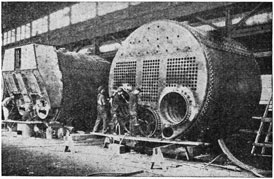
SCOTCH BOILERS UNDER CONSTRUCTION
SCOTCH MARINE BOILER
The only type firetube boiler used aboard ocean-going ships is the Scotch marine. It is a famous boiler, the first one having been installed in a ship in about 1862 and up until around 1900 was practically the only type boiler found aboard merchant or Navy ships. At that time watertube boilers began to come into use but for a number of years the Scotch marine still remained the dominant boiler. With the advent of modern high pressure power plants the watertube boiler became a necessity. However, there are still a considerable number of older American ships with Scotch boilers.
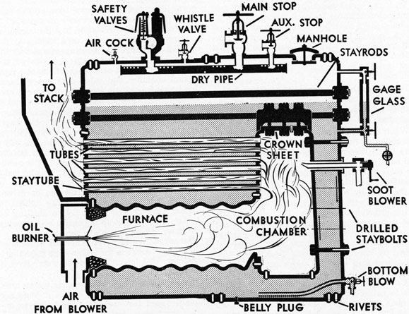
Shells and Heads-In the cross-section side view of a Scotch boiler it can be seen that the boiler has a cylindrical steel shell and flat heads the same as the simple firetube boiler. Also the upper portion of the heads are braced with stayrods in the same manner. A further study, however, reveals that something has been added to the simple boiler.
Furnaces-The fuel in the Scotch boiler is burned in a cylindrical steel furnace located
23
SIDE VIEW SCOTCH MARINE BOILER
inside the water space of the boiler. The furnace is secured by rivets to the front head and is corrugated for strength to resist the crushing effect of the boiler pressure in the water which surrounds it. The number of furnaces depends on the size of the boiler, there usually being three or four.
Combustion Chamber-The furnace opens into a combustion chamber which is simply a rectangular steel box standing on end and surrounded with water.
In the combustion chamber the unburned gases, given off from the burning fuel in the furnace, mix with air and burn.
The flat sides and top of the combustion chamber must be supported the same as the flat heads of the boiler or they will bulge inward from the surrounding boiler pressure. Small stayrods, called staybolts are used for the rear and side sheets and sometimes for the bottom. They are threaded into the sheets and in some cases have nuts at the outer ends.
From the rear sheet of the combustion chamber they extend through the water to the rear head of the boiler. In this manner the lower portion of the rear head is also supported against being pushed outward. From the side sheets the staybolts extend through the water to the shell of the boiler or the side sheet of an adjoining combustion chamber. The bottoms of combustion chambers are usually curved to make them self-supporting in which case staybolts would not be needed as shown. The front or tube sheet is supported by the firetubes which extend through the water space of the boiler to the front head.
The top sheet or roof is known as the crown sheet and is supported by crown bars and crown bolts. The crown bar acts as a bridge span from which the crown bolts hold up the crown sheet. The crown sheet is the highest heating surface in this type boiler and the water level must be kept above it at all times or it will become overheated.
24
It is the usual practice to have a separate combustion chamber for each furnace, although Scotch boilers have been built with all the furnaces opening into one large common combustion chamber. There are also double-ended Scotch boilers where separate furnaces from each end of the boiler enter into one combustion chamber.
Tubes-The tubes are made of seamless drawn steel, a popular size being 3 1/4 inch outside diameter which is the way all boiler tubes are measured.
When tubes are installed they are pushed in through the holes in the front head which are slightly larger than the outside of the tubes, and back through the water space and through the corresponding tube holes in the combustion chamber tube sheet. The tubes are made tight in the holes by rolling them around the inside at each end, with a tube expander which works on the principle of a wedge. This squeezes the tube outward tight against the inside of the hole. If properly expanded the joint will not leak unless the tube is overheated, or is disturbed by improper warming up of the boiler or becomes thin with age and wear. After the tubes are expanded, the projecting ends are bent outward and back against the tube sheet. This is called beading and is done to protect the ends from being burned off due to the heat of the fire. The beading also prevents the tubes from pulling out of the holes in the event they should loosen up.
As the number of tubes in a boiler is large, they provide by far the largest amount of heating surface.
Staytubes-A small proportion of the tubes, scattered among the firetubes, are staytubes. They are heavier tubes and are threaded into the tube sheets to give added support to the flat tube sheets and heads.
Operation-The oil burner and air registers are located in the front end of the furnace. The oil is sprayed into the furnace, mixes with the air and burns. In operation some of the heat of the burning fuel passes through the furnace walls into the water. The remainder is carried by the draft into the combustion chamber, where more of it passes through the sides into the surrounding water. The gases, still at a high temperature, next pass into the tubes where the greatest portion of the heat enters the water. The gases still containing some heat flow out the front ends of the tubes and turn
upward through the smoke box, uptake and stack, from which they are lost overboard.
Circulation-The circulation in a Scotch boiler is poor which necessitates care when starting up cold. The arrows pointing upward in the sketch on page 25, indicate the rise of the water being heated around the furnaces, combustion chamber and tubes. As can be seen, this leaves very little space for the cold water at the top to work its way down. This confliction of currents slows down the circulation.
When firing up a cold Scotch boiler, the water below the furnaces tends to lie there and remain cold. If this is not prevented the water in the upper part of the boiler will be boiling while the bottom will still be cold. This condition places a strain on the boiler, causing leaks at the joints. To prevent this, a small fire is lighted in one furnace. After ten or fifteen minutes it is shut down and a fire lighted in another furnace and so on. This shifting of the fire tends to heat up the entire boiler evenly and start the water circulating.
Dangerous Water Level-When the water level drops out of sight in the water gage glass there is no way of knowing where the water level is in the boiler.
Never assume that because the water level was in sight a few seconds before it could not have dropped far enough in the boiler to uncover the crown sheet.
Never try to bring the water level back into sight by opening the feed check valve wide, allowing water to rush into the boiler. If the crown sheet is overheated, the incoming water striking it may cause it to crack or fail, resulting in a disastrous boiler explosion.
Always shut off the oil burners immediately upon discovering a low water condition and notify the engineer.
Advantages-The Scotch boiler has certain advantages over the watertube boiler.
Due to the much larger amount of water contained in the Scotch boiler, there is a much larger amount of heat stored up which makes for steadier steaming pressure and water level.
The Scotch boiler is somewhat cheaper to build and it can use dirtier water, even sea water if necessary.
The Scotch boiler generally requires less repairs than the watertube due to there being no brickwork in the firebox to keep in repair.
Disadvantages-The disadvantages of the Scotch boiler are such as to have caused its replacement with the watertube boiler in new
25
construction of American ships for a number of years.
Its large size and weight prevents carrying as much cargo as with watertube boilers.
Due to the large amount of water and poor circulation, steam cannot be raised quickly.
All of the stored-up heat energy being contained in one large shell makes for a greater possibility of boiler explosion.
There being a limit on the thickness of steel plate that can be shaped, Scotch boilers cannot be constructed for working pressures much higher than 250 pounds per square inch which prohibits their use with modern turbine plants.
Generally speaking Scotch boilers are not as efficient to operate as watertube.
BOILER FITTINGS AND ATTACHMENTS
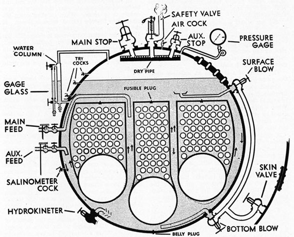
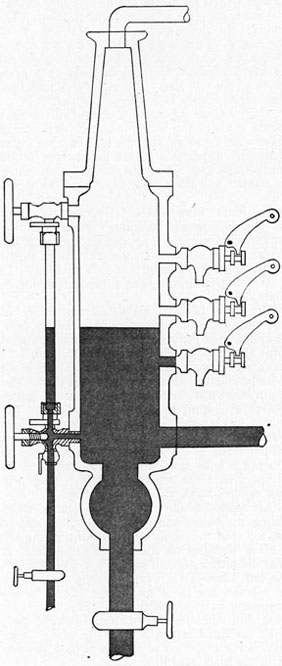
All boilers, regardless of their type or design, require a number of fittings and attachments in order to render them safe to operate. The relative position of these fittings and attachments is shown in the front view sketch of a Scotch boiler.
The fittings and attachments and their purposes are:
Water Gage Glass-As it is impossible to see the amount of water inside the boiler, a small glass tube about 12 inches long, known as a gage glass, is installed outside the boiler, in a vertical position.
The top end of the glass is connected to the top of the steam space of the boiler by a pipe
FRONT VIEW OF SCOTCH BOILER WITH FITTINGS ATTACHED
26
line while the bottom end of the glass is connected to the water space in the same manner. When the water level rises in the boiler, water will flow in through the bottom connection and rise up in the glass to the same level as the water in the boiler.
The fireman and watertender can determine the water level in the boiler by looking at the gage glass.
The position of the gage glass is such that when the water level is at the lowest visible part of the glass there will still be a few inches of water above the top of the crown sheet or in other types of boilers, the highest heating surface.
The water level should never be allowed to drop out of sight in the gage glass. If this should occur at any time, all fires should be shut down at once, and the engineer immediately notified.
The top of the gage glass is considered the high water level point in a boiler where danger of water carry-over with steam appears.
On most ships the water level should be carried at the center of the glass, however, the correct water level should be determined upon going aboard each ship.
The rolling of a ship has an influence upon the water level to be carried.
Shutoff valves which are operated from the fireroom deck plates by small brass chains are located at the top and bottom of the gage glass. When a glass breaks in service these valves are closed by pulling down on the right-hand chain. This stops the steam and water from blowing out into the fireroom.
A new gage glass can then be installed by backing off the gland nuts, removing the glands and soft rubber packing washers along with any remaining pieces of broken gage glass. A new gage glass complete with new washers is installed and the gland nuts carefully tightened. Care must be exercised to make sure the bottom end of the glass does not rest against the bottom fitting, otherwise the glass will crack and break when the steam and water enter the glass.
When the new glass has been installed, the left-hand control chain is pulled down. This opens the top and bottom shutoff valves and the water and steam rush into the glass, again showing the water level.
To remove mud and sediment accumulation which would in time plug the connection to the
glass, especially the bottom one, a drain valve is provided from the bottom of the glass. A drain pipe from the valve usually leads to the bilge. At least once each watch the fireman or watertender opens the drain valve for a few seconds, which allows a small stream of steam and water to blow into the bilge where it is easily heard. This is known as blowing down the gage glass, and is a very important duty which must not be neglected if a true water level reading is always to be had. When the drain valve is closed, the water level should immediately return to the glass. A slow return is an indication of at least a partial obstruction in the connections between the boiler and gage glass and should be immediately reported to the engineer.
To make definitely certain that the top and bottom connections are clear, the following procedure is in order. When blowing down the glass, first the top shutoff valve is closed. If the blowing noise is heard from the drain it is evident the bottom connection is clear. The top valve is then opened and the bottom is closed. If the blowing noise is still heard, it is certain that the top connection is also clear. The bottom shutoff valve is then opened and the drain closed.
The plain round gage glass will break upon becoming thinned from the scouring action of the steam from many blowdowns.
The prismatic type gage glass with which most new boilers are equipped is very unlikely to break and is much easier to read, as the water appears black in the glass while the steam is white.
The water gage glass must be looked at regularly every few seconds, as the water level can change quickly, especially in watertube boilers.
At least one gage glass is required on each boiler. If only one is provided, three try cocks will be required; but if two gage glasses are installed, try cocks will not be required, although some boilers may have them also.
Try Cocks-Another method of checking the water level in the boiler is by "try cocks" shown in the cross-sectional sketch of a water column.
Try cocks are small valves on the outside of the boiler. The lowest of the three is placed on the boiler at a point two inches above the lowest visible part of the gage glass, the center try cock at the center of the glass, and the top one at a point about level with the top of the
27
gage glass. By opening the try cocks one at a time and noting which ones water or steam squirts out of, the water level is determined.
Water Column-Used when gage glass is not connected directly to the boiler.
Consists of a vertical steel cylinder, the top
GAGE GLASS-WATER COLUMN-TRY COCKS
being connected to the steam space and the bottom to the water space.
The gage glass and try cocks connect into the column at the proper level.
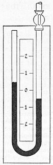
Pressure Gage (I)-To show the pressure in the boiler at all times, a pressure gage is installed. This does not have to be mounted on the boiler proper, but should be located at a point in the fireroom that is well illuminated and easily visible to the fireman.
Some pressure gages are equipped with a stationary red hand which points to the desired operating pressure. The pressure hand or pointer should ordinarily not be allowed to go above this, as to do so may cause the safety valves to lift.
The operation of a pressure gage was explained on page 6.
Safety Valves (D)-If the pressure in a boiler were allowed to increase without restriction, it would become so great that with even the strongest boilers, an explosion would occur. To prevent this happening, safety valves set to open at a pressure far below the bursting pressure of a boiler are required.
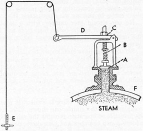
SIMPLE SAFETY VALVE
The cross-section sketch is of a simple safety valve to show the principle of operation.
The safety valve is attached to the top of the boiler shell (F). The steam under pressure from the boiler pushes upward against the bottom of the valve disc (A). The tension in a coil spring (B) pushes down on the top of the disc holding it on its seat which plugs the opening.
28
When the pressure in the boiler pushing against the bottom of the disc becomes greater than the tension of the spring, the disc lifts, leaving an opening through which the steam escapes to the open air. As long as the pressure in the boiler is kept at this point, the valve will stay open permitting the steam to rush out of the boiler as fast as it is made. This, of course, prevents the pressure from building up any higher.
When the pressure within the boiler drops, the valve spring is then stronger than the boiler pressure and pushes the valve down on its seat, which closes the opening, stopping the flow of steam from the boiler.
The pressure at which the safety valve will open is determined by adjusting the spring tension with the adjusting nut (C). The greater the tension on the spring, the higher will be the boiler pressure before the valve opens and vice versa.
To permit opening of the safety valve by hand at any pressure, a hand-relieving gear is provided. A steel cable leads from the relieving gear on the safety valve to within easy reach of the fireman on the fireroom deck plates so that in an emergency, the safety valves may be opened by simply pulling down these cables by turning the wheel screw (E).
No one should ever tamper with a safety valve. It is set by the boiler inspectors and is the only insurance against excess boiler pressure.
Safety valves have been known to stick in the closed position which in some cases resulted in a boiler explosion. To prevent this, two safety valves are required by law, being commonly built in one valve body and are known as duplex safety valves. One valve opens a few pounds before the other.
The modern safety valve is somewhat more complex than the simple one shown, although its principle of operation remains the same. By adding a pop chamber and blow-down ring the modern safety valve is able to remain open until the pressure in the boiler has dropped a few pounds. This prevents chattering of the valve due to repeated openings and closings.
Main Stop Valve-To control the flow of steam into the main steam line leading to the main engine. It is located on top of the boiler and is usually of the non-return angle globe type shown.
When this type valve is in the open position, steam can flow from the boiler but cannot
return. This prevents the possibility of steam entering the boiler through the main steam line from another boiler when it is idle.
It is very important that care be exercised when opening a main stop valve or any other stop valve on a boiler. When opening, the valve wheel should be turned to the left just enough to raise the disc slightly from its seat. The minute the steam starts to flow through, it can be heard. This is known as cracking a stop. Leave the valve in this position until sufficient steam has passed through to build up a pressure in the cold line. The stop valve may then be opened slowly to full open position.
Carelessness in opening these valves may cause some of the water in the boiler to carry over with the steam into the line, causing water hammer, which is a severe hammering action in the pipe line. If severe enough, it can cause a sudden and disastrous failure of the steam line.
Auxiliary Stop Valve-To control the flow of steam into the auxiliary steam line, the auxiliary stop valve is located on the top of the boiler. It is of the same general design as the main stop valve except that it is smaller.
When opening, the same procedure should be followed.
Dry Pipe-Located inside of the boiler at the very top of the steam space is the dry pipe. A simple type commonly used consists of a steel pipe about six inches in diameter in a horizontal position with each end closed. Many small holes are drilled along the top of the pipe. The main stop valve, auxiliary stop valve and safety valves are connected into the dry pipe. The steam leaving the boiler through any of these valves must first pass through the small holes which tends to remove water which might be traveling with the steam. This makes drier steam, hence the word "dry pipe." They will not remove large amounts of water.
Air Cock--To allow the air to escape when filling the boiler and getting up steam and to let air into the boiler when draining, the air cock is installed on the top of the boiler. It may be either a small valve or a cock.
Feed Lines-Two ways of supplying water to a boiler are required and are known as the main and auxiliary feed lines. They are identical, the main feed line being regularly used, with the auxiliary as a stand by ready to go into instant service if trouble should develop with the main feed line.
Usually both lines are equipped with internal
29
feed pipes which discharge the water away from the heating surface.
Main Feed Stop and Check Valves-Located in the main feed line with the stop valve next to the boiler. The operation of these valves is explained on page 12. Reach rods are provided on the check valve so that it may be adjusted from the fireroom floor plates.
Auxiliary Feed Stop and Check Valves-Located in auxiliary feed line in same position as in main feed line. Same construction as those in main feed line.
Surface Blowoff Valve-In boiler operation, certain impurities in the boiler water tend to collect and float on the surface of the water. To remove these a surface blowoff valve is installed on the side of the boiler. It is usually an angle type globe valve and is provided with an internal line and scum pan as shown.
When the valve is opened, the pressure in the boiler sweeps the floating scum with the water through the scum pan, internal line, surface blowoff valve, external blowoff line, and overboard through the skin valve.
Bottom Blowoff Valve-To remove the heavier loose impurities which accumulate on the bottom of the boiler, the bottom blowoff valve is installed near the bottom of the boiler. Blow-off valves may be of the angle globe type or of a type especially designed for blowoff service. In the Scotch boiler, it is provided with an internal line as shown.
When the valve is opened the pressure in the boiler blows the sediment through the internal line, bottom blowoff valve, external blowoff line, skin valve and overboard.
Skin Valve-Although not attached directly to the boiler, the skin valve must be considered, as it is used in conjunction with the surface and bottom blowoff valves. The blowoff lines from all boilers lead to the skin valve. It is always of the globe type. It is attached directly to the inside of the ship's hull, hence the name skin valve.
When blowing down a boiler, the skin valve is opened first and closed last. Its purpose is to prevent flooding of the ship in the event the external blowoff piping between the boilers and the ship's hull should break.
Salinometer Cock-Located on the boiler below the water level for removing small amounts of boiler water for testing purposes. Derived its name from the Salinometer, a crude device for determining the amount of salt in water, which at one time was the most widely used method
for testing boiler water for salt.
Belly Plug-A small metal plug threaded from the outside into a hole in the bottom of the shell of a Scotch marine boiler.
Removed when cleaning boiler, to allow small amount of water lying on bottom of boiler to drain into bilge.
Never attempt to tighten if leakage should occur when in service. The threads may be worn causing the plug to blow out, allowing scalding water to blow out.
Hydrokineter-In some Scotch boilers hydrokineters are installed near the bottom to aid the circulation when starting up a cold boiler. Steam from shore or another boiler is fed to the hydrokineter which consists of a series of nozzles inside the water space. The steam picks up velocity passing through the nozzles into the water. This pushes the water ahead of it from beneath the furnaces as shown. Steam can be raised much quicker on a boiler so equipped.
Fusible Plug-To give warning of low water condition in Scotch boilers fusible plugs are required. They are made of bronze, being round about one inch in diameter and three inches long. A tapered hole in the center extending from end to end is filled with tin which has a melting temperature of about 450° F.
A fusible plug is threaded into a hole in the crown sheet of each combustion chamber from the fire side. Should the boiler water level drop below the crown sheet, the fusible plug will be unprotected by water and the banca tin will melt, leaving a hole through which steam will blow into the combustion chamber and furnace, giving warning to the fireman.
Should a fusible plug melt on you, shut the
fires off immediately and notify the engineer. Fusible plugs are ordinarily renewed once each year.
WATERTUBE TYPE BOILERS
Due to the many disadvantages of the -Scotch boiler, marine engineers began to develop the watertube boiler for marine use, starting around the year 1900. As watertube boilers re quire much purer feedwater than Scotch boilers, their general acceptance was slow for a time due to lack of water-treating knowledge in those days. Many watertube boilers were installed in American ships during the large ship construction program of the first World War and since
30
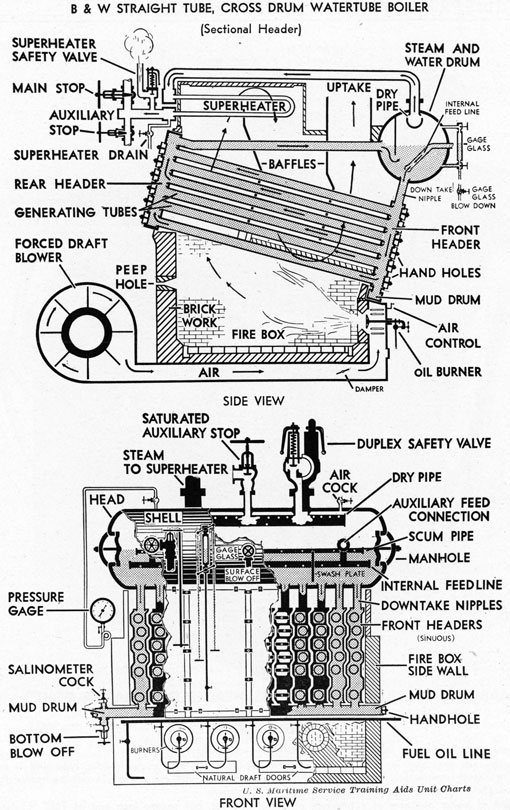
B & W (BABCOCK AND WILCOX) STRAIGHT TUBE, CROSS DRUM WATERTUBE BOILER
that time the majority of boilers installed in American ships have been watertube.
The principle of operation of a watertube boiler is the opposite of a firetube in that the water and steam are inside the tubes while the fire flows around the outside.
There are several different types of marine watertube boilers depending upon the pressure desired, amount of steam needed and the type of ship. A type that is very popular, having been installed in most of the older ships having watertube boilers, and in practically all of the new Liberty Ships and many others, is the B & W "straight tube, cross drum." The cross
sectional sketches are of this type.
The steam and water drum consists of a cylindrical steel shell about 42 inches in diameter and several feet long, the ends being closed with dished steel heads. Downtake nipples (short tubes)-lead from the bottom of the drum into the top of the front headers. Hundreds of tubes in an inclined position lead from the after side of the front headers to the forward side of the rear headers. The top of the rear headers is connected to the after side of the steam and water drum by the return tubes. Below the tubes is located the firebox which consists of four brick walls and a brick floor.
31
32
VICTORY SHIP BOILER
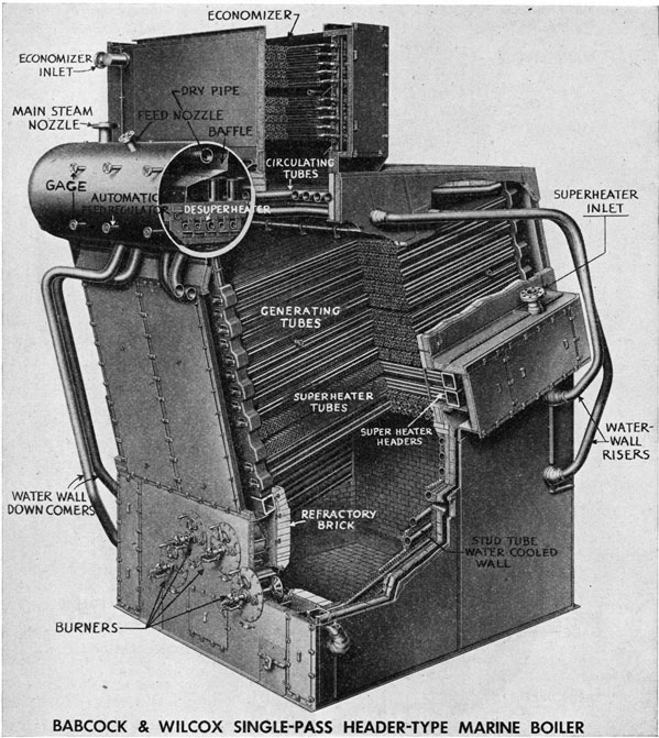
This type of boiler is used in all Victory ships.
Two such units are used in each installation. The boiler is of the sinuous header type and is equipped with an interdeck superheater. Other apparatus includes a stud tube economizer, a desuperheater to supply low temperature steam for auxiliaries; and water cooled walls.
This type of boiler operates at a pressure of about 450 lbs. per square inch and at 750° F. steam temperature.
33
STEAM AND WATER DRUM
The oil burners are located in the front wall of the firebox.
The boiler is filled through the steam and water drum. As the water enters, it flows downward through the downtake nipples, gradually filling up the headers and tubes. Water is allowed to enter until the drum is half filled.
When the oil burner is placed in operation, the fire and hot gases produced in the firebox pass upward around the rear portion of the tubes as shown by the arrows, being directed in their travel by the baffles which are nothing more than partitions between the tubes. The hot gases pass to the top, around the superheater tubes and then turn down passing around the center portion of the tubes. The gases upon striking the top of the horizontal baffle resting on the top of the bottom row of tubes, turn under the bottom of the second vertical baffle and then flow upward around the front portion of the tubes, from there passing into the uptake and smokestack.
This is known as a three-pass boiler, as the hot gases pass in three different directions over the tubes causing the gases to slow down, giving the water in the tubes more time to extract their heat.
As the fire and hot gases pass around the
outside of the tubes much of their heat is conducted through the walls of the tubes into the water inside.
As the water in the inclined tubes is heated it becomes lighter and rises, flowing into the rear headers where it rises to the top and flows to the steam and water drum through the return tubes.
In the meantime the cold water in the drum being heavier sinks down the downtake nipples into the front headers from where it flows into the tubes replacing the water heated. This cold water is in turn heated and rises. This circulation goes on continually while the boiler is in service. As the water is all flowing in one direction the circulation in a watertube boiler is good.
Tubes-The tubes are known as generating or evaporating tubes and are made of seamless drawn steel. Although their size varies in different boilers, the majority are 4-inch diameter in the bottom row and 2-inch for all others. Some of the newest of this type boiler, however, have very small tubes, 1-inch or 1 1/4-inch diameter, being installed very close together, which slows down the speed of the rising gases, making it possible to operate efficiently without baffles. The tubes are expanded for tightness in the tube holes of the headers in the same
34
manner as the firetube boiler. The projecting ends, however, are flared or belled outward instead of beaded as the ends are in water and not exposed to fire. The flaring prevents the tubes from pulling out of the headers in event of loosening up.
Headers-The headers are of the sectional type, being sinuous from top to bottom. This permits staggering the position of the tubes vertically which aids in slowing down the flow of fire and gases. The headers are made of forged steel, their cross section being square. Opposite the tube ends are handholes to permit tube cleaning and repairs.
Muddrum-Attached to the bottom of the front headers by short nipples is the muddrum which is a small square box of forged steel extending entirely across the boiler beneath the headers. This being the lowest point in the boiler circulation, the mud and sediment settle into the muddrum and to protect the box from over-heating, brickwork is installed between it and the firebox. Attached to the bottom of the muddrum at one end is the bottom blowoff valve and to the top the salinometer cock.
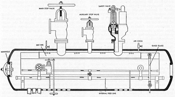
Steam and Water Drum-On page 33 a cross-sectional view of the steam and water drum shows the various valves and fittings. The dished heads at each end are secured to the ends of the shell plate by fusion welding in all modern boilers. In the center of each head is an elliptical shaped manhole opening, about 11 inches by 16 inches in size, which is sufficiently large for the average sized man to enter the drum for cleaning and repair work. The left-hand head has the manhole plate in place with a gasket between it and the head for tightness. The gaskets are the ring type generally of woven asbestos. When installing they should be well coated with a mixture of flake graphite and steam engine cylinder oil, to prevent the gasket from burning fast to the plate and head. Never enter an empty boiler until positive that all valves are closed, sign on front of boiler stating that there is a man inside, and the engineer knows you are entering. Men have been scalded to death from steam or boiling water entering through an open valve from another live boiler.
Attached to the top of the drum are the pipe line to the pressure gage, the main stop valve, auxiliary stop valve, duplex safety valves and air cock.
Inside of the drum the dry pipe may be seen running along the top with the main and auxiliary
stop valves and safety valve connecting into it. A few of the small holes through which the steam enters along the top can be seen.
The small perforated pipe line running along the center of the drum is the surface blowoff scum pipe which takes the place of the scum pan. The surface blowoff valve shown attached in the center of the pipe is actually on the outside of the drum.
The main feed check valve and stop valve are on the outside of the drum near the left end. The check valve is provided with a reach rod to permit its adjustment from the floor plates by the fireman. The feedwater passes into the perforated internal feed line which extends the length of the drum to permit the feedwater to be discharged downward into all the downtake nipples. The auxiliary feed check and stop valves not shown, connect onto the right-hand end of the same internal feed line.
One of the water gage glasses complete with its top and bottom connection shutoff valves, is shown near the right-hand end of the drum. In most of the boilers the water level should be carried midway of the glass.
The downtake nipples lead out of the bottom entirely across the drum, each nipple discharging into the top of a separate front header. Only three of these are shown.
Superheater-The convection type superheater shown at the top rear of the boiler consists of a number of 2-inch tubes bent in the shape of the letter U, which allows the tubes to expand and contract at will. The saturated steam from the steam and water drum passes through the steam line into the superheater inlet header, then through the U tubes into the outlet header from which it passes into the main steam line. The steam passing through the U tubes picks up considerable heat from the hot gases flowing around the outside of the tubes. This added heat gives the steam more energy without increasing its pressure. At the superheater outlet a main and auxiliary steam stop valve and a thermometer and pressure gage connection are provided. (See page 31.)
Other type superheaters are interdeck, installed about midway between the banks of boiler generating tubes; and radiant located near the radiant heat of the firebox. The nearer to the fire the superheater is installed, the hotter will be the superheated steam.
When firing up a cold watertube boiler care must be exercised not to put too large a fire in the firebox, otherwise the superheater tubes will
35
be damaged from overheating due to the fact that there is no steam to flow through the tubes to protect them until steam is formed in the boiler.
Firebox-The firebox walls are of high temperature firebrick to resist and hold inside the 2000° F. or more temperature of the burning fuel. The front wall around the oil burners is formed with special cone-shaped high temperature refractory material. Unless the brickwork is treated properly it will soon crack, crumble and begin to tumble down. This means repair work for the crew in port. Even slight flare-backs (combustion explosions) from careless handling of the oil burners can cause damage to the brickwork. Allowing cold air to blow in on the hot brickwork when shutting down a boiler will also cause damage.
When this type boiler is built to operate at high pressures it is necessary to protect the firebox brickwork from the increased firebox temperatures. This is accomplished by installing waterwall tubes. These tubes are of the same general type as the generating tubes but are located either in an inclined or vertical position in front of or within the firebox brick walls. The tubes are connected into the circulation of the boiler and installed very close together. In this manner practically the entire brickwork is protected from the heat by a wall of water. The heated water in the tubes rises to the steam and water drum and returns to the tubes from the drum by an outside pipe connection. Besides protecting the brickwork, the waterwall tubes provide additional heating surface, making it possible for the boiler to produce more steam.
Baffles-Act as partitions between the tubes to slow down the hot gases and direct them over all of the tube heating surface. Those near the firebox are made of high temperature refractory material to withstand the heat while those between the tubes may be of cast iron.
Baffles can also be damaged by slight flare-backs.
Sootblowers-With the best combustion, burning fuel oil produces some soot, which travels with the hot gases and lodges on the outside of the tubes. Ordinarily this should be removed each day, otherwise the heat has difficulty getting to the tubes, resulting in fuel wastage. Today practically all oil burning boilers are equipped with sootblowers which make an easy job of removing the soot. Four sootblower elements are usually installed in the straight tube cross drum type watertube boiler shown in the two views. A sootblower element consists of a
long pipe extending through one side wall of the boiler, between two rows of tubes nearly to the opposite side wall. Holes are located all along one side of the pipe. Dry steam is admitted from the boiler through the sootblower control valve on the end of the pipe outside the boiler side wall. As the pipe is slowly turned from the outside, the steam escapes through the holes, blowing the soot from the outside of the tubes. An excessive amount of forced draft is used during this operation to carry the loosened soot through the passes and up the stack overboard.
When operating it must be made certain that dry steam is used, as wet steam will mix with the soot, setting up a condition that will cause rapid corrosion of the tubes.
Sootblowers must be kept in adjustment, otherwise the escaping steam may rapidly cut holes in the tubes.
During wartime sootblowers must only be used when authorized, due to the danger of smoke being seen by the enemy.
Scale and Oil-One of the most important things in successful, trouble-free, watertube boiler operation is to keep the water side of the boiler clean. Any appreciable formation of scale or mud in a tube directly over the fire is almost certain to cause overheating with resultant tube failure. Modern methods of treating the water in the boiler practically eliminate this possibility if the treatment is properly kept up.
Oil and grease are almost certain to cause tube failure, especially if the boiler is being forced.
Dangerous Water Level-As in all boilers, the water level in a watertube boiler must not be allowed to drop below the bottom of the gage glass. To do so may leave some of the boiler tubes dry, resulting in their overheating. Although the danger of disastrous explosion may not be as great as in a Scotch boiler, terrific damage has been done to both men and property by a bursting boiler tube. The most important job of a fireman and watertender is to keep the water level in sight and at its proper steaming level.
Advantages-Due to the diameter of the drums being relatively small, watertube boilers may be constructed for very high pressures, at least one boiler having been built for 2,000 pounds per square inch. Since they are smaller and lighter than the Scotch boiler, it is possible for the ships to carry more cargo.
Steam may be raised quickly on a cold boiler. If necessary it may be safely done in an hour with most boilers.
36
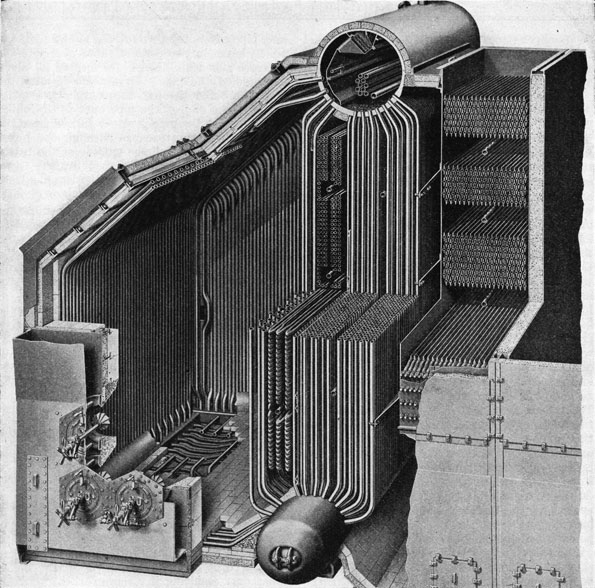
C-E MARINE TWO-DRUM WATERTUBE BOILER
This modern type, high pressure, bent tube boiler, is also known as "D" type. It is installed on some of the high speed tankers and cargo vessels.
Its construction is compact, fitting nicely into the ship's hull.
The oil burners are located in the front of the firebox at the left side. The firebox walls are lined with waterwall tubes, the top ends of which enter the steam and water drum. The bottom ends are expanded info a header, which is connected to the muddrum by floor tubes.
The superheater tubes are of the radiant type, located near the firebox, between the vertical generating tubes.
The economizer tubes are at the lower right-hand corner and above them the air preheater tubes.
In operation the fire and hot gases pass upward around the waterwall tubes and generating tubes nearest the firebox. A vertical baffle directs the hot gases downward around the right-hand section of generating tubes. From here they turn upward passing around the economizer and air preheater tubes to the uptake and stack.
The hottest gases are in the firebox, causing the water in the tubes surrounding it to rise upward from the muddrum to the steam drum. From there it settles down the cooler generating tubes at the right side.
37
Watertube boilers may be forced without harming them.
The water and steam being separated into relatively small sections reduces the possibility of a disastrous explosion.
Watertube boilers may be assembled in the ship, making for easier installation in many cases.
Disadvantages-Due to the small amount of water contained and steam stored it is more difficult to maintain a steady steam pressure and water level, especially when the main engine is being maneuvered. The fireman must act quickly at this time, when lighting off and shutting down burners and adjusting feed check valves.
Watertube boilers must have better water than the Scotch marine.
Watertube boilers cost more to build.
Due to the firebox being constructed of brickwork there is apt to be more repair work.
AUTOMATIC BOILER FEEDWATER REGULATORS
Most modern marine boilers operating from pressure of 400 lbs. upward are equipped with automatic feedwater regulators which maintain a proper water level without the necessity of manual regulation of the feed check valves. Each boiler has its own regulator located in the main feedline just before the feed check and stop valves. Although most regulators satisfactorily maintain the proper water level always remember that, as a mechanical device, it should not be trusted. The water gage glass should be watched as closely as though the feedwater was being regulated by hand.
One type of automatic regulator works on the principle of a float on the surface of the water in the steam and water drum. As the float rises and falls it operates, through a lever arrangement, a regulator valve in the feedline. When the float drops, the regulator valve opens, allowing feedwater to enter the boiler. As the water level rises so does the float which, by closing the regulator valve, decreases the amount of water entering the boiler.
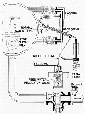
Shown in the cross-sectional sketch is another type of feedwater regulator, known as the Bailey Thermo-Hydraulic Feedwater Regulator, which operates on the thermo-hydraulic principle. This consists essentially of a pressure generator and a feedwater regulator valve. The generator is a metal tube which is surrounded
by a larger metal tube. The upper end of the inner tube is connected to the steam space of the boiler. The lower end of the inner metal tube is connected to the water space of the boiler. The outer is connected by copper tube to a metal bellows in the feedwater regulator valve. The space between the inner and outer tubes is filled with water. The steam in the inner tube causes the water surrounding it
BAILEY AUTOMATIC FEEDWATER REGULATOR
to flash into steam, building up a pressure which forces the water down the copper tube into the bellows. This pressure causes the metal bellows to expand, forcing the feedwater regulator valve open against the tension of the coil spring. When the water level rises in the boiler it also rises in the inner tube taking the place of the steam. As this water is relatively cool from having been trapped in the U-leg, it lowers the temperature of the water between the inner and outer tubes. Contraction of the water in the bellows permits the coil spring to close the regulator valve.
To remove any accumulation of sediment in the water leg, the blowdown valve should be opened once each twenty-four hours.
38
DRAFT
To make steam, fuel must be burned, but before fuel can burn oxygen must be supplied to it as it is the oxygen combining with the carbon in the fuel that results in combustion. Air contains oxygen, so air must be supplied to the furnace or firebox of a boiler and the method of doing this is called draft.
NATURAL DRAFT
The only type of draft known for many years was natural draft. When a fire burns in the open, such as a bonfire, natural draft occurs. What happens is that the hot gases given off by the burning fuel are lighter than the surrounding air and rise upward. The colder surrounding air being heavier sinks down and flows into the fire.
In a boiler the hot gases rise up the stack and the relatively cold air in the fireroom sinks down and flows into the front of the furnace. The hotter the gases in the stack and the colder the air outside, the better will be the draft. The direction and strength of the wind and the ship's course and speed also have an influence on natural draft. It is evident then that the amount of natural draft is for the most part dependent upon several uncontrollable factors, which limit the amount of fuel that may be burned in a boiler. This in turn limits the amount of steam that can be produced. When a greater quantity of steam is necessary some other means of supplying air must be provided. This is known as forced draft.
FORCED DRAFT
Forced draft is used entirely with oil-burning marine boilers and to a considerable extent with coal. There are several types of forced draft, the most popular type being where a large steel-bladed fan known as a blower is used. The fan takes air from the fireroom or engine room and blows it through a sheet metal duct (trunk) to the furnace front which is sealed from the fire-room to prevent natural draft from entering. By controlling the speed of the fan the exact amount of air needed for proper burning of the fuel can be supplied at all times. The blower is driven by a steam engine or an electric motor.
Closed Fireroom-In a few large passenger ships a type of forced draft known as closed fireroom is used. With this type the fireroom is sealed and the blower, which is located above it, forces the air directly into the fireroom, placing
the entire fireroom, including the fireman, under pressure. The furnace fronts around the oil burners are left open, allowing the air to rush into the furnaces. When entering or leaving a fireroom of this type it is necessary to pass through an air lock, otherwise the air pressure would rush out when the door is opened.
Induced Draft-Still another type is induced draft. With this the blower is located in the uptake leading from the boiler to the stack. The blower creates a small vacuum in the furnace, causing the fresh air in the fireroom to rush in through the open furnace fronts. Another method of producing induced draft, no longer used, is a steam jet pointing upward in the stack. The velocity of the escaping steam leaving the nozzle creates a vacuum which causes the air to rush into the furnace. The large waste of heat and water prohibits its use.
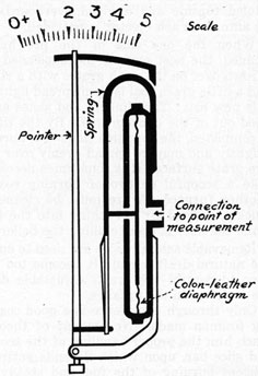
MANOMETER (DRAFT GAGE)
DRAFT GAGE
Draft pressure is so slight that it cannot be measured with an ordinary pressure gage so a glass U tube known as a manometer is used. One end of the tube is connected by a small pipe line to the duct through which the air is being blown to the furnace or to another part of the
39
boiler or uptake. Between the legs of the tube is a scale graduated in inches. The U tube is half filled with colored water. When the blower is started up, the air pressure in the duct becomes greater than the atmosphere and travels down the pipe pushing the water down somewhat in that leg of the U tube. This causes the water to rise up a corresponding amount on the open leg. The distance in inches between the water levels in the two legs is the pressure of draft. When the blower is speeded up the number of inches between the water levels becomes greater. When slowed down they become less. Draft then is measured in inches of water, one inch being equal to about .036 of a pound pressure.
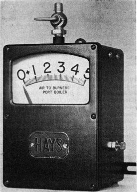
CROSS SECTION HAYS GAGE
Modern marine power plants quite often use the Hays leather diaphragm type gage, which operates on an entirely different principle. In this gage the air pressure enters through a connection from the duct or furnace and pushes
against the side of a slack leather diaphragm. This pushes the diaphragm in and through a series of connected levers, links and springs the pointer is moved over a graduated scale marked in inches. To determine the amount of draft the fireman merely has to note the particular number of inches in front of the pointer.
Draft gages are usually located in the fire-room at a point easily visible to the fireman.
Draft pressure drops rapidly as it flows along a duct or passes through the boiler. In modern boilers draft gages are connected to several points in the boiler and uptakes so that the draft pressure all through the boiler may be known at all times.
HAYS DRAFT GAGE
In wartime it is especially important that the proper amount of draft be carried at all times to prevent a smoking stack. In the daytime a little too much draft is better than too little. At night excess draft may cause sparks to fly from the stack.
40
FUELS
Anything that will burn may be called a fuel. The only kinds used in marine boilers are coal and fuel oil.
COAL
Up until the first world war, bituminous (soft) coal was about the only fuel used in marine boilers, but at that time fuel oil began replacing coal in American ships until today nearly all burn oil. There are, however, a few coal burners left which necessitates a brief discussion of coal and its burning.
Bituminous coal contains on the average about 14,500 B.T.U.'s per pound, and upon analyzing the coal we find that it contains more than half carbon, about a third volatile matter and a small ash and sulphur content. It is the carbon in the coal uniting -with the oxygen in the air that produces the fire.
Handling and Firing Coal-All coal burning marine boilers are hand fired, which means that more firemen are required than when oil fuel is used, and in addition, several coal passers.
Greater time and expense are required to load coal and more space is required for its storage, resulting in less cargo space than with oil fuel. The coal is stored in bunkers (compartments) adjacent to the fireroom, from whence it is removed in buckets or wheelbarrows by the coal passers who pile it on the fireroom deck plates as needed. The firemen, using scoops, shovel it into the furnaces.
The best firing results, with least smoke, are usually obtained by carrying a thin fire. This requires that the fireman shovel in coal in small amounts and often, rather than large amounts less often. This procedure will depend somewhat upon the quality of the coal; however, it is generally found to be the best firing method.
In most cases it is best to spread the coal evenly over one-half of the fire at a time rather than to cover the entire fire with green coal. This alternate firing makes for steadier steaming and less smoke.
As the coal burns, ash and clinkers form within the fuel bed next to the grate bars and must be removed. To remove the ashes, the slice bar is pushed inward beneath the fire on the top of the grate bars. This causes the ash to drop through the grates into the ash pit. This
also breaks up the fuel bed sufficiently to permit air to pass through.
The presence of dark spots in the ash pit indicates that clinkers have formed in the fuel bed. These must be removed, as they reduce the heat of the fire. To do this requires that the fire be cleaned frequently.
To clean a fire, one side of the fire is allowed to burn down until only the clinkers and ashes are left. These are pulled out the furnace front onto the deck plates by the fireman, using a long-handled hoe. The heat of the clinkers falling on the deck plates is quenched by sea water from a hose in the hands of the coal passer. The clinkers and ashes are placed in steel buckets, hauled topside and dumped overboard, unless an automatic ash ejector is provided.
When the one side of the fire has been cleaned, the best part of the uncleaned side is thrown over on the clean grates with a slice bar, and a little green coal is then spread lightly over this new fire. The clinkers and ashes are then hoed out of the unclean side. By the time this is completed, the first side cleaned is burning up brightly and may be spread evenly over the entire grate surface. It is sometimes necessary to take a scoopful or two of burning coal from another furnace. A fire must be cleaned very quickly, as cold air is rushing into the furnace while the door is open, chilling the boiler.
Removable ash pit doors are used to cut down the natural draft, should it become too strong. Also to control the draft, adjustable dampers are installed in the uptakes.
Only through experience is a good coal burning fireman made. No amount of theory can teach him the proper handling of the scoop, hoe and slice bar, upon which depends entirely the efficient burning of the fuel and steady steam pressure.
FUEL OIL
Fuel oil has a number of advantages over coal as a fuel for marine use. Being in liquid form, it is brought aboard through a hose, eliminating much hand labor. It is stored in spaces of the ship not possible with coal, such as the double-bottoms, which means more space available for cargo. Less firemen are required in the handling and burning of coal. The problem of ash
41
disposal is eliminated. The engine compartment and the ship in general can be kept much cleaner. The steam pressure can be kept steadier than with coal. When burning oil it is not necessary to continually open and close the furnace doors, doing away with large amounts of cold air rushing into the furnace and chilling the boiler which often results in leaky tubes.
Although the price of oil is usually higher than coal its many advantages make it more economical to burn in the long run.
Fuel oil is a heavy-bodied oil that is the residue left from crude oil after the various grades of gasoline, kerosene and lubricating oils have been removed at the refinery.
It consists of about 85% carbon and the remaining 15% consists of hydrogen, oxygen, nitrogen, sulphur, sand and water.
The principal measures of the properties of fuel oil are:
Flash Point-The temperature at which the oil gives off vapors that will ignite but will not burn steadily. The oil becomes dangerous at this point, as explosions can occur. When handling and storing, fuel oil must be kept below this temperature for safety's sake. Rules and regulations require that marine fuel oil shall not have a flash point below 150° F. This is to prevent inflammable vapors from forming in the storage tanks under ordinary atmospheric conditions. The flash points of fuel oils vary according to the body of the oil. It can only be determined by test.
Fire Point-is a temperature above the flash
point at which the oil gives off vapors that burn continuously.
The flash point and fire point may be determined by heating oil in an open dish in which is placed a thermometer. An open flame is held above the oil. When spurts of flame occur the temperature of the oil is noted. This is the flash point. When the vapors given off burn steadily the temperature is again noted. This is the fire point.
The temperature of the fuel oil at the burners must be sufficient to permit the oil to atomize thoroughly.
Viscosity-is a measure of the oil's body, which means its rate of flow. A heavy-bodied oil flows more slowly than a light-bodied one.
Temperature affects the viscosity. When an oil is cold the viscosity increases, when hot it decreases.
The viscosity of an oil is determined by passing a sample of the oil to be tested through a viscosimeter. Briefly, a viscosimeter consists of an open dish in which 60 c.c. of the oil to be tested is poured. It is heated to a standard temperature of 70° F. When 70° F. has been reached the oil is allowed to run out the bottom of the dish through a standard-sized opening. The number of seconds it takes for the oil to run through is the Saybolt second viscosity of the oil. The heavier the oil the longer it will take for it to run through and the higher will be its viscosity. The lighter the oil the quicker it will run through and the lower will be its Saybolt second viscosity.
42
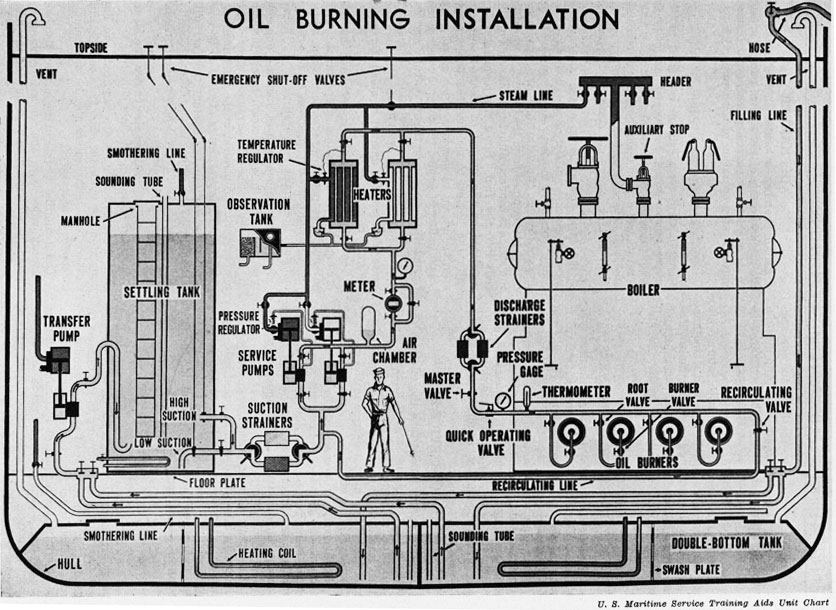
OIL BURNING INSTALLATION
The simple principle of burning fuel oil is to reduce the viscosity to the proper point and place it under pressure so that the oil burner can break it up into many small particles like a mist, in which form it sprays into the firebox or furnace. This permits the thorough mixing of air with the oil, necessary for good combustion, and is known as atomization.
Several pieces of equipment, which are known as the Oil Burning Installation are required for the storing, handling and heating of the oil. The sketch shows the relative location of the various pieces of equipment in a typical mechanical pressure type oil burning system.
STORAGE TANKS
Storage tanks are located in the ship's double-bottoms beneath the cargo holds and wing tanks on the ship's side. Several pieces of equipment are required to be fitted to the tanks.
For filling the tanks a filling line which branches off to each tank is installed from topside. The branch lines are equipped with shutoff valves to control the flow of oil to each tank. The filling line enters the top of the tanks and must extend downward to discharge within 6 inches of the bottom of the tank or be equipped with a gooseneck to discharge the oil upward. When taking fuel aboard constant vigilance must be maintained to prevent one or more of the tanks from being overflowed. Besides wasting the fuel, it is difficult to clean up. If fuel oil should spill into the harbor the ship may be heavily fined by the port authorities.
A vent pipe leading from the top of the tank is required to permit air and any inflammable vapors to escape to a safe point above the ship. The discharge end of the vent pipe is provided with a gooseneck and must be covered with a flame screen. The flame screen is made of wire gauze and its purpose is to prevent flame from burning vapors on the outside traveling down the vent into the tank. The screen must be kept in good condition, never painted and always in place.
Steam heating coils are necessary along the bottom of the tank so that the heavy oil may be heated to lower its viscosity so that it may be pumped. This is especially necessary when the ship is in cold water. The fuel in the tanks should never be heated higher than 150° F. To
go above this may cause inflammable vapors to be given off.
Entering the top of each tank is a fire smothering pipe line equipped with control valve. CO2 (carbon dioxide) is the most popular agent used on modern ships for fighting fire. Previously live steam was used. In the event of fire in the tank the smothering valve is opened allowing the CO2 to flow into the storage tank and extinguish the fire.
A manhole is provided in the top of each tank to permit entrance for cleaning and repairs. A fuel oil tank should never be entered until it has been gas freed and tested for sufficient oxygen. Never enter without a safety line attached and someone tending it on the outside. Men have lost their lives by being careless in this respect. The breathing of oil vapors or the lack of sufficient oxygen will cause a man to be overcome very quickly.
Fuel oil is sold by volume, making it necessary to consider the temperature when purchasing.
Storage tanks are not filled more than 90% full, allowing room for expansion in the event the oil should become warmer after being stored.
TRANSFER PUMP
Transfer pump removes the oil from the storage tanks through the suction valve and line, and discharges it through the discharge line into the settling tanks.
SETTLING TANKS
Settling tanks are located in the fireroom, usually one on each side. Here any water that may have come aboard in the oil is allowed to settle to the bottom. Also there is always the possibility of sea water entering the storage tanks through leaks in the ship's hull.
If water reaches the burners in any quantity the fires will go out. A slight amount will cause the fires to sputter.
The water that accumulates on the bottom of the settling tanks is pumped out through the low suction valve and discharged either overboard or into a disposal tank while the oil for the fires is usually removed through the high suction.
It will, be noted that internal gate type shutoff valves with extension control rods to
43
Oil Burning Installation
44
topside are provided at the high and low suctions. This is required by Rules and Regulations, to prevent flooding of the fireroom with fuel oil in the event of an emergency, such as a fire in the fireroom.
Settling tanks are provided with internal filling line, heating coils, vent pipe, and a smothering system the same as the storage tanks. After the oil passes through the external high or low suction shutoff valves it passes through the duplex suction strainers.
DUPLEX SUCTION STRAINERS
Duplex suction strainers are a basket type strainer of coarse mesh to prevent stones or other good-sized foreign matter in the oil from entering and damaging the fuel oil service pumps. Only one strainer is used at a time, the other being cleaned and kept as a standby. The strainers must be changed and cleaned each watch, otherwise they may become clogged with dirt preventing the flow of oil to the pumps.
FUEL OIL SERVICE PUMPS
Fuel oil service pumps take the oil from the settling tanks and discharge it under pressure to the fuel oil heaters and burners.
At least two pumps are required, one being a spare ready for instant service in the event of trouble with the other.
Regulation of the speed of the pump varies the pressure of the oil and controls the amount of oil being burned. The desired oil pressure for best atomization in most modern burner systems is from 100 to 250 pounds per square inch.
The steam line supplying steam to operate the pumps is provided with a shutoff valve having an extension rod leading to the topside, preferably the boat deck. This makes possible the stopping of the pump from outside the fire-room in an emergency.
METER
The oil leaving the pump under the desired pressure passes through a meter which registers the amount of oil flowing to the burners in gallons. The meter is read at the beginning and end of each watch by the engineer or fireman to determine the amount of fuel burned during the watch. Readings are entered in the engine room logbook. The meter is equipped with a by-pass line in the event of trouble.
AIR CHAMBER
An air chamber is located in the system on the discharge side of the service pumps, acting as a cushion to reduce pressure fluctuation caused by the operation of the pump.
OIL HEATERS
In the oil heaters, the oil is heated to the proper temperature to reduce its viscosity to the point where it will atomize best. This temperature will depend upon the grade of oil being used, and is usually posted in the fireroom.
All fuel oil heaters use steam as the heating agent.
One type heater is a closed steel vessel through which a number of steel coils pass vertically from head to head. As the fuel oil flows upward through the coils, which are surrounded by live steam piped from the boilers, the heat in the steam is conducted through the walls of the coils into the fuel. Since the temperature is regulated by the amount of steam allowed to enter the heater, to increase the temperature open the steam valve wider which allows more steam to flow in around the coils. To reduce the temperature, close in on the steam valve and reduce the amount of steam entering. Remember that when the amount of oil flowing through the heater changes, the amount of steam for heating must be changed.
Generally temperature is regulated by the fireman but some heaters are equipped with automatic temperature regulators which admit just the right amount of steam at all times to maintain the proper temperature.
Another type heater uses just the opposite type principle, in which steam passes through the coils while the oil surrounds them. The temperature is controlled in the same manner.
If the oil temperature is allowed to become excessively high in the heaters the fuel will carbonize in the coils and its heating ability will be reduced. This will also make it necessary to clean the coils.
Excessive temperature also causes the oil to vaporize resulting in the fires pulsating.
At least two heaters are required, one being a stand-by while the other is in service. In most systems both heaters may be used simultaneously if necessary.
The steam line leading to the heaters also has a shutoff valve with control rod reaching to topside for emergency shutoff outside the fireroom.
45
THERMOMETER
Thermometer is installed in the oil line on the discharge side of the heater so that the temperature of the oil is visible at all times to the fireman on watch.
DUPLEX DISCHARGE STRAINERS
Duplex discharge strainers, through which the oil next flows are of the same general construction as the suction strainers except that they are smaller in size.
As the hot oil is thin (low viscosity) it is possible for it to pass through fine mesh strainers which remove fine particles of foreign matter such as sand, which would interfere with the atomization of the oil in the burners. It is important that strainers be changed over each watch and the dirty one cleaned and left ready for the next change.
MASTER VALVE
Located in the branch oil line to each boiler is a master shutoff valve. By closing them the flow of oil to all burners is stopped. Used in an emergency or when a boiler is out of service.
BURNER VALVES
Two shutoff valves are installed in the branch line to each burner providing double insurance against leakage of oil into the firebox when the burner is shut off.
RECIRCULATING VALVE
When starting up a cold oil burning system the recirculating valve at the end of the oil line is opened permitting the cold oil to return through the recirculating line back to the suction side of the service pump. When hot oil reaches the burners this valve is closed and the burners lighted.
46
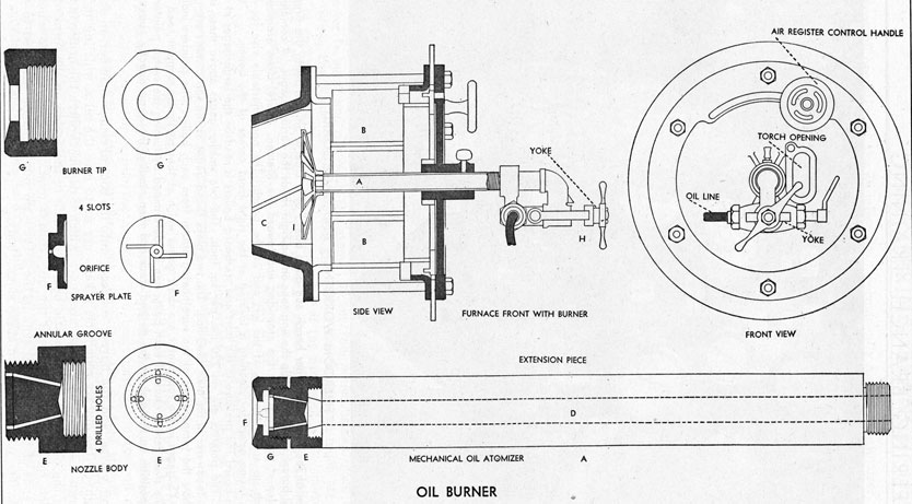
BURNING FUEL OIL
To burn well, fuel oil must be sprayed into the firebox in the form of a mist. This is known as atomization and is accomplished by the oil burner, a cross section of which is shown. The oil enters through the atomizer (A) which is the heart of the burner. The air
enters the firebox around the atomizer through the air register openings (B). The air scoops (C) direct the air into the firebox in the proper direction to mix thoroughly with the atomized oil.
In the enlarged cross-sectional view of the atomizer the fuel oil enters the atomizer from the fuel oil line after passing through the two
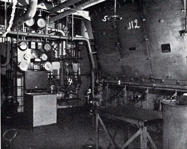
LIBERTY SHIP FIREROOM
This view of the Liberty Ship fireroom shows the front of the number 2 (starboard) boiler. The fuel oil line (1) is across the front of the boiler with two shutoff valves in the branch line to each burner. Directly below (3) is the fuel oil thermometer and master valve. One of the fuel oil service pumps is on the forward bulkhead at (4) while a feed check valve adjustment wheel is overhead at (5).
47
48
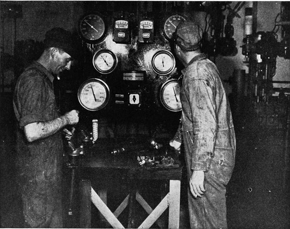
FIREROOM WORKBENCH AND GAGE BOARD
This is a view of the fireroom burner bench and gage board of a Liberty Ship, showing the fireman on the left cleaning oil burner atomizers while the engineer on the right reads the various gages. A complete atomizer lies in the center of the bench with the atomizing end toward the fireman. Spare, clean atomizers with the connection ends up are in the rack at the left end of the bench. The non-adjustable vise for holding the atomizer when taking apart for cleaning is located at the right front corner of the bench.
On the gage board the pressure in the port and starboard boilers is read on the large gages at the bottom of the board. The pointers are on 220 lbs. per sq. inch. The two smaller gages above these indicate the pressure of the feedwater in the main feed line. The two black faced gages at the top corners are temperature gages which show the temperature of the superheated steam from each boiler. The pointers indicate about 440°. The HAYS gages in the top center are draft gages which at that particular moment read slightly less than I inch. The stack temperature of each boiler can be determined by turning the switch pointer at bottom center to the position on the dial for the desired stack and then reading the gage directly above it.
burner shutoff valves, and the burner connection made tight by the quickly removable yoke. Traveling down the inside of the atomizer extension piece the oil comes to the nozzle body through which four drilled holes lead the oil to the outer ends of the tangential slots in the sprayer plate. The oil rushes down these slots
into the conical center chamber, in such a manner as to give the oil a whirling motion with which it passes through the orifice in the sprayer plate to the firebox in the form of a hollow cone of mist. The sprayer plate is held in place by a tip nut which is threaded to the nozzle body.
49
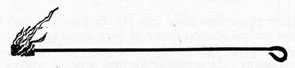
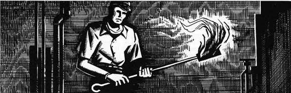
The successful operation of the atomizer depends upon the oil being at the proper viscosity (controlled by the oil temperature) and the oil being under pressure (controlled by pressure regulator on the fuel oil service pumps). Also the sprayer plate and nozzle body must be kept free of all dirt or foreign matter. This necessitates the atomizer in each burner being removed and cleaned each watch by the fireman. To do this both burner shutoff valves and the air register are closed. This stops the oil from entering the atomizer and prevents unnecessary cold air from blowing into the firebox while the burner is shut down. The yoke is then slacked off and the complete atomizer drawn out of the burner barrel first allowing the small amount of fuel oil in the atomizer to drain into the drip pan hanging beneath the burner. A spare cleaned atomizer is then installed by sliding it into position in the burner barrel and connected to the oil line by tightening the yoke. Make sure this yoke is tight otherwise hot oil will spray out into the fireroom when the burner valves are opened. A torch consisting of a steel handle about three feet long with a small ball of braided asbestos soaked in kerosene at one end is lighted. This is inserted through an opening in the front of the burner to permit the flaming torch to be directly in front of the sprayer plate. The burner valves are then opened, permitting the oil to rush through the atomizer emerging in a fine mist where it is ignited by the torch. The air register is then opened wide permitting air from the forced draft blower to enter and mix with the atomized oil. When the burner is operating the air register is always in the wide open position. When shut down it is fully closed. There is no intermediate adjustment.
BURNER TORCH
Always stand to one side of the burner when lighting of and do not look into the firebox. Should a flareback occur flame may shoot out in your face.
To clean the dirty atomizer it is placed in a special non-adjustable vise secured to the fire-room work bench. If it should ever be necessary to place the atomizer in an adjustable jaw vise do not squeeze it too tightly as to do so will
permanently distort the atomizer, ruining it for further use. Back off the tip nut with the burner wrench. The sprayer plate is then lifted off with the fingers and washed in kerosene. Never use anything but a pointed stick or a copper wire for removing carbon or other sticky substance. A knife or steel nail will scratch the metal surface and enlarge the orifice which destroys the effectiveness of the atomizing action. Remember the sprayer plate is an accurately machined part which must remain that way to atomize the oil. After the four holes in the nozzle body have been cleaned the sprayer plate is replaced and the tip nut screwed on and tightened with the burner wrench. The B. & W. oil burner has a small fine mesh strainer in the entering end of the atomizer which must also be removed and cleaned each watch.
Sprayer plates are made in sets, each set having a different sized orifice. The larger the orifice the more atomized oil can enter the firebox, so when the oil pressure is at its highest permissible working pressure and more steam is needed, the burners will have to be shut down one at a time and sprayer plates with a larger sized orifice installed in the atomizers. Size numbers are stamped on the outside face of all sprayer plates, the engineer determines what size sprayer plates are to be used.
In the burning of atomized fuel oil the proper amount of air must be supplied at all times. Not enough air will cause incomplete burning of the fuel which causes black smoke to pour out of the stack. Too much air causes a chilling of the fire, with white smoke coming from the stack. In peacetime smoke is a sign of fuel being wasted. In wartime it can easily result in an attack by the enemy, for smoke rising into the air can be seen for many miles by a prowling enemy submarine. It is most important that the fires be carefully tended to eliminate all smoke.
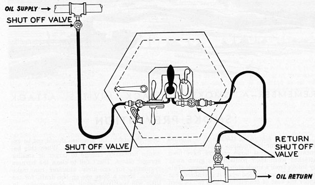
VARIABLE CAPACITY BURNER
Oil Burners in General-Modern burners have two basic parts: the fuel oil atomizer which breaks up the solid oil stream into spray and the air register which controls the air admitted for combustion and directs the flow of air into and around the oil spray. Most burners have changeable tips to provide for changes of load; the variable capacity burner uses one tip for all loads.
50
Variable Capacity Atomizer and detail sketch of sprayer plate.
Variable Capacity Burner-This type of burner is designed primarily for boilers using forced or induced draft. The oil supply is constantly recirculated as indicated by the arrows on the enlarged drawing of the atomizer. The oil enters the large supply tube and flows toward the tip. The oil supply pressure is kept constant.
The orifice plate and the sprayer plate change this pressure to velocity and give the oil a swirling action. Some of the oil is now forced into the smaller outside passages and will return to the day tank if the oil return line valves are open. The oil which is not returned will emerge
from the orifice plate into the furnace in a hollow conical shaped spray of very small particles of atomized fuel oil.
Closing the return oil line shutoff valves stops the flow of oil away from the burner. This increases the amount of oil sprayed into the furnace and, if the mixture of air and oil is proper for good combustion, the capacity of the burner can 'be increased for hard steaming.
When the shutoff valves in the return line are opened, oil flows out of the burner and the air is cut down, reducing the size of the flame. In this manner the burner can be adjusted for any load without changing the burner tip or the pressure on the service pump.
51
Sketch showing oil flow to and from burner.
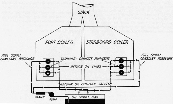
All burners on one furnace can be controlled by one Return Control Valve as shown above.
52
REMEMBER-A SMOKING STACK INVITES ATTACK
SMOKE PREVENTION
In wartime a smoking stack is to be avoided at all costs, for information secured from the enemy reveals that large convoys have been attacked when their position was given away by smoke from a single ship in the convoy. This can be easily understood when it is realized that under the best of conditions a ship can be seen by a submarine from a distance of not more than 12 miles. Under ideal conditions smoke is visible 30 or more miles.
To keep the ship from smoking requires constant alertness on the part of the engine room crew. When burning coal, thin fires should be carried, the coal being shoveled in the furnaces in relatively small amounts. With oil fuel, the temperature of the oil must be kept at the proper degree, for if it drops below any considerable amount, black smoke is sure to pour
from the stack. Oil pressure should not be exceeded one way or the other. When this becomes necessary, change to larger or smaller sprayer plates. Don't fail to clean the burners regularly, for one dirty atomizer can make smoke. Keep a close eye on the draft, for too little will positively result in black smoke. In the daytime it is better to carry a little more draft than necessary than not enough. At night excessive draft may blow sparks into the air above the ship so keep the draft where it should be.
The sootblowers must not be used except when authorized by the engineer as the ship is bound to smoke while this is going on.
Remember-keep a clear stack.
53
FIRE EXTINGUISHERS IN FIREROOM
In all firerooms of oil burning vessels this fire-fighting apparatus is required by law:
Sand-A minimum of ten cubic feet, contained in a metal receptacle, and provided with a scoop. This receptacle should be kept full at all times with sand and the scoop never used for anything except fire fighting.
Hand System-Either of the following: Two 2 1/2-gallon foamite extinguishers or two 15-pound carbon dioxide extinguishers.
Portable System-Either of the following: One 40-gallon foamite extinguisher or one 100-pound carbon dioxide extinguisher.
Permanent System-This consists of perforated piping running under the floorplates through which the fire extinguishing agent passes. This agent may be steam (although steam is now losing its rank among agents), carbon dioxide, or foamite. The fire extinguishing agent is released from some point outside the fireroom; before it is released, all persons
should be warned to leave the fireroom. After such a system has been used, no one should enter the fireroom until it has been found that there is enough oxygen for human existence.
It is the generally accepted theory that water is not good for oil fires. Nor is it good, if played on the fire under pressure and in the form of a powerful stream from a nozzle. However, there is on the market, and has been accepted, a special nozzle which sprays the water in a fine mist in the fireroom. Now, as long as this special nozzle is used water is accepted as an oil fire extinguishing agent. Some vessels use this as their portable system.
When a fire is discovered act quickly, for a small blaze may be easily extinguished by throwing sand on it or using a hand extinguisher whereas a few moments' indecision may result in a conflagration beyond all control. Remember the ship is your world until you are back on land, so take care of it.
54
RAISING STEAM
In preparing to raise steam on a dead boiler it is necessary that the following accessories and valves be closed:
Bottom blow valve
Surface blow valve
Belly plug, Scotch boilers
All feed stops and checks
Salinometer cock
Drain on gage glass or water column
All steam stops
Whistle valve
All manholes
All handholes
The following valves should be opened:
The air cock
Safety valve
Top and bottom connections to gage glass and water column
Valve to steam pressure gage
If there is no water in the boiler, it is put in through the main feed line, if possible, until the water just shows in the gage glass. Then water is put in through the auxiliary feed line to be sure this line is operating properly. After the water is at the proper level the feed stops and checks are all closed again.
Before lighting off an installation of oil burners, the boiler furnaces should be blown through with air to drive out the gases or vapors from the oil which may have accumulated there. This is done by opening the air doors in the registers of several of the burners. Atomizers must be clean, and all valves on pipes leading to the individual burners should be closed. The oil is circulated through the recirculating line until the oil right up to the burner is at its proper temperature, and pressure.
If the temperature of the oil is not high enough to maintain the proper low viscosity, it will be difficult to atomize the oil properly resulting in smoke conditions and carbon deposits in the furnaces. Excessive heating of the oil
above the proper temperature will cause carbon deposits in the fuel oil heaters, waste steam, and will cause the burners to pulsate. Whenever the oil is at the proper temperature and pressure, the burners may be cut in.
The burner nearest the center of the boiler is lighted first. A torch is lighted, the air register closed, the torch inserted into the furnace, the oil turned on, and then the air register is opened again.
The boiler should never be forced, and the burners which are lit should be shifted from center to wing to opposite wing, etc., so as to heat the boiler evenly throughout. Steam should never be raised too quickly in any boiler. In Scotch boilers this tends to distort the entire boiler shell, causing ruptures of the tubes, furnaces, or the shell itself. In watertube boilers, raising steam too quickly is not injurious to the boiler itself, but the rapid temperature changes cause furnace brickwork troubles. The bricks tend to buckle and the walls will soon tumble down.
Never in any event, for any reason, should the fires be lit in any boiler without using a torch to light them. It is imperative never to attempt to light fires from hot brickwork. The results of such practice always lead to flare-backs which, although they may not be serious enough to cause injury to the fireroom personnel, will still cause extensive damage to the furnace walls.
When steam blows out of the air cock it should be closed. Likewise the safety valves. Pressure should start to show on the pressure gage very shortly thereafter. Bring the steam pressure up slowly until equal with the live boilers and cut in on the line by carefully opening the auxiliary steam stop valve.
55
REMEMBER-ALWAYS USE A TORCH TO LIGHT A BURNER
DUTIES OF A FIREMAN
The fireroom watches are of four hours each. This means that in 24 hours there are six watches; the 12-4, 4-8, and 8-12 A.M. and P.M. A fireman stands an A.M. and a P.M. watch, with eight hours off in between.
The oiler on watch rings "two bells" on the engine room bell at ten minutes before the relieving hour. The relieving fireman enters the fireroom at this time and begins his inspection of the plant.
The first and most important thing that the fireman must do on entering is to look at the boiler gage glasses. Make certain that the water in the boiler is at its proper level. If the fireman is responsible for tending the water in the boiler, blow the glasses down to ascertain the accuracy of the water level. The fireman works under the direction of the watertender if one is on watch.
The fireman then makes an inspection of the fires and the burners. Take note of the condition of the tile cone around the burner front to see if there is any carbon built up in front of the atomizer upon which the oil will impinge. Look for oil leaks at the connections of the oil lines and burners. Inspect the fireroom and the tank tops below the floor plates for oil drippings that may cause fires. Make sure that all spots of oil are wiped up on the floorplates and in the pans below the burners. Take note of the pressure gage readings at various points in the oil line to ascertain the conditions of the oil strainers. Check the oil heaters by looking at the thermometer on the oil line to see if the proper temperature is being maintained. Look in the fireroom bilges to see that they are
empty, check the pressure of the oil in line at the gage nearest to the burners, and then the steam pressure of the boilers. After everything is apparently all right ask the fireman who is going off watch if he has had any trouble during his watch, and if there are any special orders for you from the engineer. If all is found to be as it should be, take over the watch, relieving the fireman on duty of all responsibility.
55
The fireman should never be lax or late in his inspection when relieving a watch. Always remember that when you relieve the other man, the full responsibility for the maintenance of the fireroom is yours for the next four hours. Whatever conditions may exist, regardless of who is to blame, the responsibility will be yours alone.
Always allow yourself enough time to make your complete inspection before eight bells ring in the engine room. This marks the beginning and ending of the watches. Never make a man you are relieving remain below after his watch is over unless you find something wrong due to his negligence while he has been on watch. In this case do not relieve him until he has remedied the condition.
After taking over the watch, the next problem is to make sure that everything goes smoothly during your watch. Change over the suction and discharge strainers and clean the ones that have been in use, replacing them in the body of the strainer, and leave the strainer and floor plates around the strainers clean for the next watch.
Next change all burners. These are changed
56
alternately from boiler to boiler and never more than one in a boiler at a time. While a burner is being changed it is out of use for the few minutes that it takes to complete the operation. During these few minutes, there is the same amount of water entering the boiler as before but there is less steam being made. Therefore an excess amount of water accumulates, raising the level in the boiler.
After the burners have been changed and cleaned, the strainers changed and cleaned, and the watch is running smoothly, the fireman's duty is to make an inspection of the plant at definite intervals. Don't just sit down and wait for your relief. Trouble is a thing that will come quickly to the lazy fireman. A small speck of dirt the size of a pin point can stop up a burner to the extent that the direction of the oil spray can be diverted enough to strike the brickwork of the furnace. This oil does not burn but cokes and forms carbon on the brickwork. This carbon continues to build up and in the short period of a half-hour a piece of carbon large enough to completely block the burner opening can form. This will cause improper combustion in the furnace and soot will form
on the tubes of the boiler causing considerable loss of efficiency and a lot of work.
The fireman must watch his plant at all times just as the engineer watches his.
Each fireman is responsible for keeping a part of the fireroom in a neat and tidy condition. The particular part being known as your station. The painting, shining of bright-work, etc., connected with this station is done by the fireman while he is on watch. However, this work is never in such a part of the fireroom that at any time the performance of these duties interferes with the safe operation of the boilers. At all times, the fireman should be at a point where his water gage and steam pressure gage are visible.
A fireman should do everything possible to maintain the boilers in a safe operating condition at all times with a maximum of efficiency. You should be familiar with the pipe lines and auxiliary machinery in the fireroom and know how to prevent and combat fires that may start at any time.
Keep a close watch on the stack for smoke, either by looking at the top of the stack itself or through the smoke density indicator.
57
DUTIES OF A WATERTENDER
The watertender is carried aboard ships which have several boilers and where the tending of the water in the boilers requires constant attendance. Some boilers, such as the Scotch boiler, although they require constant attention do not require that a change in the setting of the check valves be made often. Other boilers require frequent change in the setting of the check valves in order to maintain the proper water level in the boilers.
The duties of the watertender include the following: Be thoroughly familiar with the construction of the boilers, the accessories connected with them, and know their purpose and operation. These accessories include the external and internal feedwater lines, and the stop and check valves that control the feeding of the water to the boiler, the safety valves, the main and auxiliary steam stop valves, the steam pressure gage, the water column and gage glasses, the injector, the feed pumps, try cocks, bottom and surface blowdown valves and piping connected with blowing down the boiler, the hand release on the safety valve, superheater drains and connections, air cock, all valves used in conveying steam from the boiler to all parts of the ship, sootblowers, etc. The watertender must at all times be aware of the hazards incurred from low water and maintain a safe level in the boilers.
Because the firing of the boiler directly
affects the water level in the boiler, the water-tender must direct the fireman ill his duties. He oversees the fireman and as a rule, is responsible for maintaining a steady steam pressure in the boiler.
When the boilers are supplied with automatic feedwater regulators, the watertender should be familiar with their operation, and should never rely entirely on their operation, but still maintain a constant surveillance of the water level.
The watertender must have a thorough knowledge of the engine and fireroom firefighting equipment.
The watertender should be thoroughly familiar with the safe handling and burning of fuel oil. He must be able to properly operate the fuel oil system from the tanks to the burners. This requires a thorough knowledge of all the oil burning equipment including the transfer lines and pumps, valves, manifolds, etc., strainers, service pumps, heaters, control valves, atomizers, and regulating valves.
He should have a good working knowledge of draft, and the particular draft equipment on the vessel on which he is employed, for it is his duty to minimize smoke conditions at the stack, and maintain good furnace conditions.
In short, the watertender should be able to operate and maintain the fireroom watch with as little assistance from the engineer as possible.
58
THE WIPER'S JOB
The wiper is not a qualified member of the engine room in the true sense of the position. He is an all-around worker in the Engine Department of an oil-fired vessel. His is the only position open in that department for beginners and others not qualified in the more responsible ratings. The wiper washes paintwork, chips, scrapes, paints, and performs all those various duties tending to maintain the machinery spaces in a clean condition.
Generally he is a day worker, and is not assigned to a watch. He should, as quickly as possible, familiarize himself with the hazards of using oil fuels, and operating pressure vessels.
Since he is first, last, and always a seaman, he should be familiar with nautical terms. He should realize the importance of emergency drills, know his stations in each, and be able to fulfill his part should the necessity arise to combat fire or abandon ship. As an engine department worker he should have an interest in mechanics, and be familiar with the names and the purposes of all the units in the power plant of the vessel.
Where overhauling and repair work of boilers
and machinery is carried on, the wiper helps in various ways, and it is through the knowledge that he gains while doing this work that he prepares himself for advancement.
The records of all successful men show that they were not afraid to assume additional duties. They were not hesitant about asking questions-nor did they begrudge a small portion of their leisure time for study.
This applies to any line of endeavor and even if the job is temporary, the knowledge gained will always be useful.
Duties aboard ship, particularly in the engine room, are unique in the large number of opportunities available.
The operation of a ship's engine room covers many subjects. There is much to learn that is both interesting and profitable-get as much as you can, make the most of your opportunities. Help the oiler, the fireman, the water-tender, learn the other fellow's job and don't hesitate to do a little extra work. Use at least part of your leisure time every day to read about the equipment around you. Every Chief Engineer was once a wiper who took advantage of his opportunities.