Wooden Lower-masts are made of several pieces, united by dowels or coaks, and hoops.
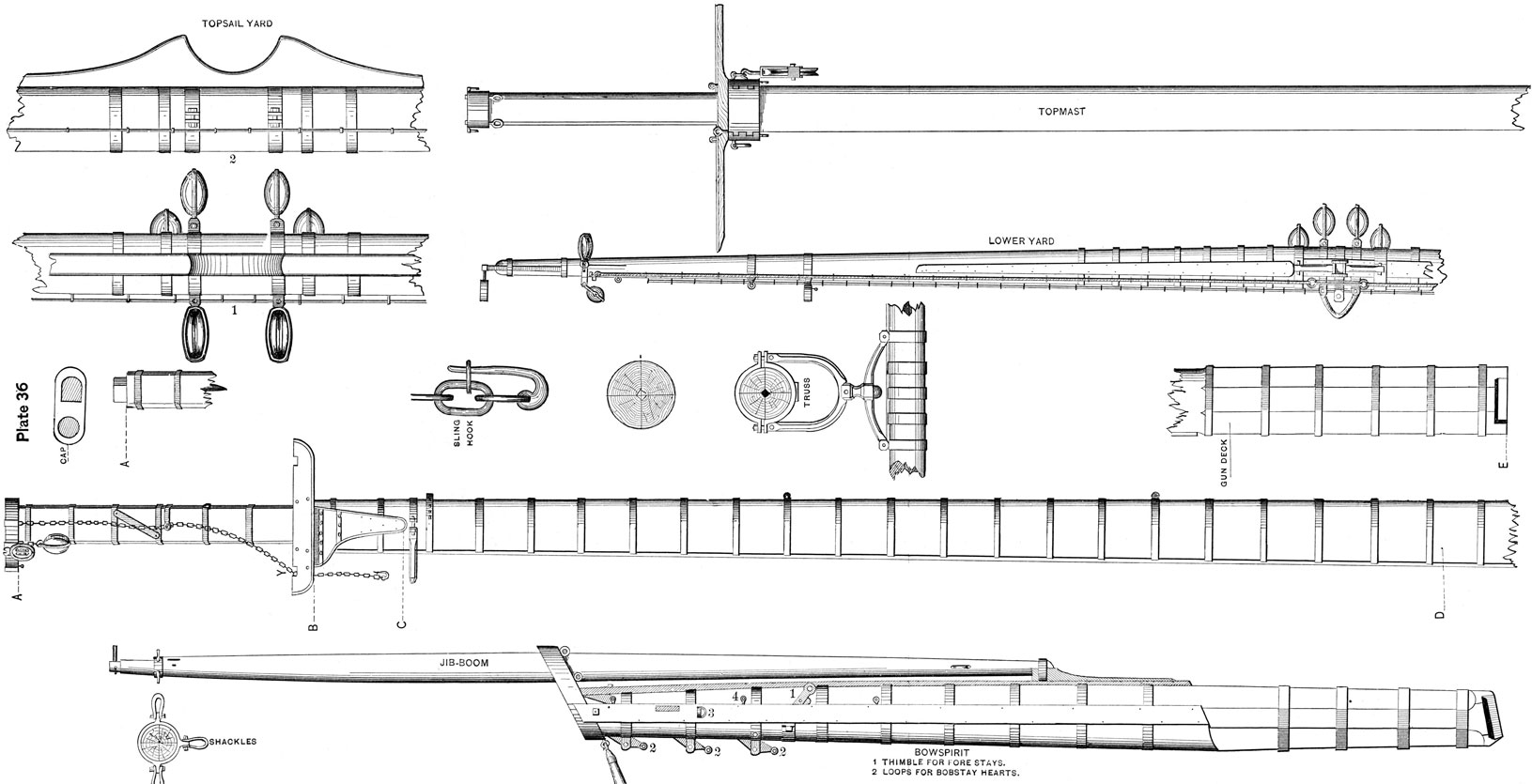
In the United States Navy, the made masts consist of four principal pieces, each of which consists of two or more parts, scarfed together, when a whole piece, of sufficient length, cannot be obtained. These pieces are placed as in Plate 36 P. The inner corner of each piece is taken off so as to leave a square hole extending throughout the whole length of the mast, in its axis. This admits of a closer contact of the parts of the mast with each other when the hoops are set up, and does not take from the strength of the spar. This hole is one-tenth of the diameter of the mast in size.
The hoops are placed from three to three and a half feet apart from each other, and are from four and one-quarter to five inches wide, and from four-eighths to five-eighths of an itch thick, according to the class of ships the mast is made for. They must, however, be kept clear of the wedges at the partners. The scarfings of the piece must be kept clear of each other (that is, the points of junction in one piece must be as far as possible from those in another piece), and equally distributed in the mast. There is a chafing batten on the forward part of the mast, about one-fourth the diameter of the mast in width, and one-eighth in thickness.
The principal parts of a mast are the head, hounds, bibbs, neck, partners and heel.
The head, A B, Plate 36, extends from the upper extremity of the mast to the top of the hounds, and is one-sixth of the whole length of the mast, nearly.
The hounds are the shoulders produced by enlarging the diameter of the mast a few inches at the lower limit of the head.
To the sides of the hounds of the lower masts are bolted, and otherwise secured, fitted pieces of oak, of the shape shown in Plate 36, and called bibbs (B c). These, with the hounds, form the foundation for the tressle-trees. The small part of the mast, just below the bibbs, is called the neck.
Where the mast is wedged, at D, is called the partners; but a more correct definition of the term is given on page 7.
81
The lower part of the mast, E, is called the heel, and the upper projection, A, the tenon.
The doublings of masts are where the head of one mast doubles on the heel of the other.
The yards, booms, and masts are usually made of yellow pine and spruce. The latter is selected for small spars.
Masts are most liable to decay at the heel, partners, and cap.
Masts are most liable to spring at the partners, tail of bibbs and hounds; bowsprits at the cap and on top between the gammoning and cap.
Tops are constructed of two thicknesses of white or yellow pine, with the rim, lubber-band and battens of white oak. The upper cross-trees are fayed down over the battens, and secured to the lower cross-trees by bolts at each end, and by four staples and toggles, so as to be readily removed when it is necessary to lift the top.
The Bowsprit is represented in full length in Plate 36. At the side the bees are shown extending from the cap to the housing, or where the octagonal form commences.
The parts marked 2 are of iron, and to them shackle the hearts for the inner, middle, and cap bob-stays.
The bowsprit cap is iron-bound. To an eye-bolt on the lower side is hooked the dolphin-striker.
Above the strap for the middle bobstay is an eye-bolt, to which hooks the whisker, 3.
Next outside is a sheave for the fore-topmast stay. An iron strap marked 1, containing a heavy, solid thimble, is for the fore-stay. There is one on each side.
Eye-bolts are represented on top of the bees, for bowline blocks, 4.
The eyes to which shackle hearts for bowsprit shrouds are not represented.
The Jib-Boom is represented in its place. The heel is cut to fit in a saddle bolted on the top of the bowsprit, and is clamped down by an iron strap; a short distance outboard is a sheave for a heel-rope.
Just inside the hounds is a sheave-hole for the jib-stay. Over the hounds fits an iron band having three shackles; one for the jib martingale stay, and one each side for the jib-guys. Immediately outside this band is a score for the foretop-gallant stay.
Lastly comes the wythe, a species of iron cap to support the flying jib-boom.
The Lower Mast has the cap on. To an eye in each end of a strap passing over the cap, shackle the chain slings for the lower yard. A back-strap about halfway down the mast-head, gives it a better lead.
The double block, hooked to an eye-bolt in the cap, is for the lower lift. The single block is the top-block for sending
6
82
up the topmast. The chafing-batten is shown on the forward side.
The tressle-trees are in place. Just below the bibbs comes the band for the patent truss, and below it the futtock-band to which shackle the futtock-shrouds.
The Topmast has the cross-trees and cap on.
The forward part of the tressle-trees has a clamp. By opening this the sending up and down of the top-gallant masts is greatly facilitated. The eye-bolts under the tressle-trees are for the hanging-blocks for the head halliards.
One gin-block, for topsail-tye, is represented in its place. It should be hooked to the eye of a strap fitting over the tressle-trees and between the doublings.
In the forward part of topmast cap, are eye-bolts for the top-gallant top-block, and standing part of top-gallant mast-rope. Fitting over the topmast cap is an iron strap with a link in each end for block of topmast studding-sail halliards.
The Lower Yard has in the centre a stout iron span, to which hook the slings.
The two lower blocks are for the topsail-sheets. The two partly concealed are for the clew-garnets and hook on the forward quarter.
On the after side of the yard is nailed a chafing-batten.
Next outside is the quarter-iron for topmast studding-sail boom.
Next comes an iron burton-strap.
Outside of it is shown the eye-bolt for head-earing of the course.
On the yard-arm are the brace and lift blocks, shackled to an iron band.
Outside of all is the "pacific iron" on which fits the boom-iron.
The bending-jackstay (iron) is seen on the top of the yard.
The truss is shown in a separate figure.
The transverse section of the mast P shows the method of joining the principal pieces of which a mast is made.
The Topsail Yard, in two views, shows the jaws, tye-blocks, bending-jackstay, quarter-blocks for topgallant sheets and additional blocks, forward, for top-sail clew-lines.
Over the topmast head is frequently fitted a rectangular funnel of metal with a projecting flange at the base to receive a quarter-round piece of wood, or bolster, upon. which the eyes of the rigging rest.
Round funnels are also fitted for the top-gallant and royal mast-heads, and on them are fitted the eyes of the top-gallant and royal rigging.
Yard-Slings, Y, Plate 36, are of chain, in length twice that of their respective mast-heads; to which must be
83
added half the length of the forward lower cross-tree, that being the distance the yard should hang below the top. The upper section, i.e., above the top, should be shackled together, keckled with a piece of large stuff to make it round, and neatly covered with canvas. The size of the chain necessarily depends on the weight it is required to support.
They hook to the yard by the sling-hook, as represented in the plate.
Preventer Slings for topsail yards, used when preparing for action, are made of chain and go around the mast-head.
Iron Masts. In the equipment of ships one of the modern applications of iron has been its use in constructing lower masts.
An iron lower mast is made up of plates, each bent to form an arc of a circle, usually 120 degrees, and connected at the edges and ends by through-riveted lap-joints or covering strips, the structure being usually stiffened by continuous interior T, or angle-irons.
Iron masts are commonly made of the same diameter as the wooden masts they have replaced, and for large ships are generally lighter than wooden masts of the same dimensions. The iron lower masts used in the British navy are more expensive than wooden masts of the same dimensions, and are of nearly equal weight, but the advantages gained in strength and durability are such as to outweigh the consideration of expense.
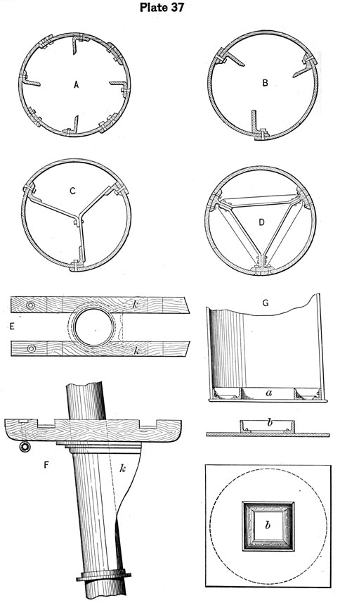
Fig. A, Plate 37, shows the section of an iron lower mast, in which there are four plates in the circumference, connected by double-riveted lap-joints, and stiffened by four continuous angle-irons worked upon the centre of each plate.
Fig. B, Plate 37, shows the angle-iron stiffeners placed so that the edge riveting shall work in as fastenings in the stiffners.
In order to stiffen masts still further, the flanges of the stiffening bars are often connected by braces or horizontal stays. These stays afford a means of climbing up inside the mast for the purpose of inspecting, cleaning and painting it. The stays are placed at intervals of from 4 to 6 feet. Fig. C, Plate 37, shows the earlier, and Fig. D the latest practice in the British service in strengthening the iron lower masts.
Figs. E and F, Plate 37, show the mode of fitting wooden trestle-trees to an iron mast. As there are no shoulders at the hounds, special provision has to be made for supporting the trestle-trees, and this is accomplished by working a plate and a ring of angle-iron around the mast, and fitting plate-knees, k k, which correspond with the bibbs usually fitted below the trestle-trees of a wooden mast. The plan E
84
shows the spread of the knees and the arrangement of the plate and angle-iron below the trestle-tree.
It is usual to work doubling plates upon the lower masts in the wake of the wedging decks. These plates give additional rigidity in wake of the wedges, and also prevent corrosion in the mast-plate Itself.
Fig. G, Plate 37, shows the ordinary mode of forming the heel of an iron lower mast. The end of the mast is dosed by a circular plate fitted against and connected with the outside plating. In the centre of this plate there is a square hole, around which the angle-iron frame a is fitted, the vertical flange of the angle-iron thus forming the sides of a mortice in the heel. When in place, the mast rests on a stepping plate, upon which is riveted a rectangular box-shaped frame of iron b, and the tenon thus formed fits into the mortice in the heel of the mast.
A man-hole is usually cut a few feet from the lower end of an iron mast to give access to the interior and for ventilation; other openings are also made at various heights for the latter purpose.
Iron and steel have also been used in the construction of topmasts, topgallant masts and yards, but in these spars the advantages resulting from the change from wood are not so great as in the case of lower masts. The details of construction for the lighter spars do not differ greatly in principle from those described for lower masts. The plating is usually flush-jointed, and the larger spars have angle-iron, or other interior stiffeners.
Masting. In fitting out our men-of-war, advantage is taken of every facility which a navy-yard affords. The rigging is cut out by the draft furnished by the constructors, using the Equipment Book of Allowances as a guide. The masts are placed by the navy-yard sheers, and the hold stowed by regular stevedores.
When the navy-yard sheers are used, the mast is brought down from the spar-shed and placed with its head toward the ship under the sheers, or masting-derrick, the garland lashed on and the main purchase toggled, the fall being taken to the capstan, or crab, built for the purpose. Convenience determines which mast is to be taken in first. After placing one mast, the ship is hauled ahead, or dropped astern, to bring the other partners plumb under the purchase.
In the following outline of masting, the work is assumed to be done without the conveniences of a yard. The vessel, a frigate, is supposed to be lying in the stream, and her spars, &c., towed off.
Proceed to support the spar-deck for the weight it will have to sustain, by shoring it up fore and aft,* particularly
* Shores are stout pieces of timber or joist, placed under a beam and resting on a block. To give the deck above a proper support, they must be wedged up.
85
those beams immediately under the places to be occupied by the sheers when getting in the masts.
Sling skids outside leading from the gunwale to the channels, and from the channels to the water's edge; block up a half-rounded spar in the hammock netting, the upper surface being well slushed, to lead the parbuckle over, and proceed.
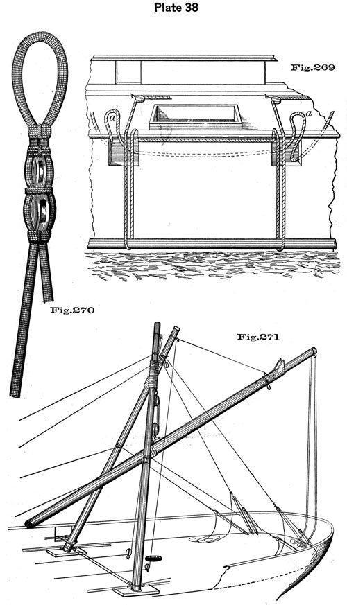
To Reeve the Parbuckle, Fig. 269, Plate 38. The main parbuckle consists of a hawser of a suitable size-say 5-inch-which is middled and the ends rove through the spar deck ports, a few ports apart (the distance depending on the length of the sheer legs), from out, in, leaving the bight outside. The sheer legs having been towed alongside, with their heads aft, pass the after end of the parbuckle down under the head of the first sheer leg, up over the gunwale to the opposite water-ways, where the end is snatched and led forward, having a long luff clapped on it, if found necessary. The forward end of the parbuckle is led in like manner, taking it under the heel of the sheer leg, and thence to the capstan.
The Counter Parbuckles, a a, Fig. 269, are rove in a contrary way, for easing the sheer legs inboard. They are rove through the same ports, from in, out, leaving the centre bight inboard, and the two end bights hanging down inside to catch the sheer leg when it comes over the gunwale; the ends are led down through the gun deck ports and taken around spars lashed fore and aft in the ports, having hands to attend them to ease the sheer legs down. Have a stout spar laid across the gunwale well aft to rest the heads of the sheer legs on when on board.
When ready, clap on the luff, man the bars, and "walk away." When "high enough," or up with the gunwale, "avast heaving," arrange the counter parbuckles under head and heel, and set taut. Now pull up on the main, and ease away on the counter parbuckle, land the heel on the deck, the head resting on the thwartship spar placed for the purpose, roll it over, lift the heel over the capstan and get it in its proper position for forming the sheers; a spar may be placed from the gunwale to the capstan, and the sheer leg got thence to the opposite water-ways. The second sheer leg is got on board in the same manner, and placed for lashing.
NOTE. Instead of using parbuckles, the sheer legs may be got on board by means of a pair of small sheers, raked over the taffrail.
Fore and main topmasts or lower yards may be used for sheer legs; in the latter case, the yard-arms must be well strengthened, or fished and woolded, by lashing around them small spars, or made fishes of stout oak plank, using well-stretched rope, and tautening the lashes by wedges. The lashing around the spar is termed a woolding.
86
The Sheers. The sheer legs being on board, cross their heads (with the port leg uppermost if the masts are taken in on the starboard side), square the heels and spread them about two-thirds the breadth of beam at the mizzen partners, so that when spread out to their full extent, the sheer head lashings may be tautened.
For sheer head lashings, take a piece of good 3 1/2 or 4-inch rope, well stretched, middle it and make one end fast to the sheer leg, near the cross; with the other end pass the requisite number of figure-of-eight turns round both spars and take a couple of half-hitches with the end around one leg. With the first end, pass a number of round turns, filling up the intervals between the figure-of-eight turns, pass frapping, or cross turns, and secure the two ends with a square knot.
After passing the sheer head lashing, spread the heels and place them in the shoes. The shoes should be of stout oak plank, long enough to rest upon at least two of the spar deck beams. A saucer is cut out of the centre to rest the heel in, and on the forward and after side an eye-bolt is placed for lashing the heel to. There are eye-bolts in the forward and after ends, for hooking fore and aft shoe-tackles to, to aid in the transportation of the sheers. Lash the heel to the shoe temporarily. Hook the after heel tackles to straps around the heels and set them taut, and, as an additional security, when raising the sheers, shift the forward heel tackles aft.
The Main Purchase. Lash on the upper block of the main purchase, so that it will hang directly under the cross. It should be a large threefold block, strapped with two single straps and fitted with a large thimble, to hang by a lashing passing over the cross of the shear head.
The straps of the main purchase blocks should be well parcelled and marled. The lower block is double-strapped, with eyes for toggling, Fig. 235, Plate 31. Take the lower block of the main purchase to the bowsprit hole, and toggle it there with a suitable spar.
The fall should be new 5 1/4-in. Manilla rope. Begin with the standing part and reeve it from forward, aft, through the side sheave of the upper block, beginning on the side opposite to that intended for taking in the masts; thence through the corresponding sheave in the lower block, and so on until rove full, when clove hitch it around one of the forks close to the lashing, and stop the end down to its own part. Snatch the fall in some convenient place near
where the lower block has been toggled, and take it to the capstan.
If apprehensive that the upper purchase block will slue in its strap, by the greatest strain coming on one side, the fall may be rove so as to lead from the centre sheave-
87
but this brings a cross in the fall, and is, therefore, objectionable.
The Small Purchase, Guys, &c. The upper block of the small purchase is double, and lashes to the after fork so as to play clear of the main purchase. Lash a single block to each fork above the small purchase and reeve stout girtlines. For sheer-head guys, clove-hitch a couple of stout hawsers over the sheer head, leading two ends forward and two aft, and to each clap on a luff-upon-luff for convenience in setting up and easing off, without surging. Belly guys are put on in the same way, about one-third the distance down each leg, cleating the hitches to prevent slipping, and clapping on luffs. On each sheer leg just above the shoe, put good straps, and hook and set well taut a thwartship tackle to ease the strain on the water-ways; lastly, pass a bulwark lashing either to the bulwark, or to a stout toggle placed outside of the spar-deck ports.
Raising the Sheers. The main purchase fall, being led to the capstan, the heels temporarily lashed to the shoes, and the forward and after shoe and heel tackles, both hooked aft, to prevent the sheers from launching forward as the strain is brought on the main purchase; the thwart-ship heel tackle set well taut, and plenty of hands to take in the slack of forward guys, and others to attend after ones, man the capstan, and heave around, catching the sheers as they rise, by the thwartship spar.
When nearly up and down, or at an angle of about eighty degrees with the spar deck, "avast heaving," lash the heels in the shoes securely, shift the forward heel and shoe tackles, cast off the bulwark lashings, and transport the sheers to just forward of the mizzen partners (having previously wet the deck), by moving one leg at a time. The sheers should have a slight rake aft, and the main purchase hang plumb with the mast-hole. The fall may lead through a block toggled through the ward-room sky-light and thence to the capstan. When the sheers are in position, set up the after head and belly guys, leading to the quarters; and the forward ones, leading well forward; set taut the thwartship tackle, and pass the bulwark lashings, or substitute for it a good tackle-the main object of which is to prevent the opposite heel from rising when raising the mast from the water. Now overhaul down outside the main purchase and toggle to the garland on the mizzen-mast. Fig. 271, Plate 38.
The Derrick. It may occur that the angle of the sheers with the deck, before raising, is so small that the main purchase will not be effective, in which case it will be necessary to start them up with a derrick, as follows:
A small stout spar (say a stump top-gallant mast) is
88
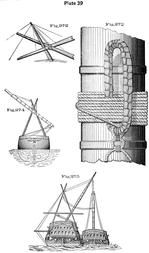
placed between the cross of the sheer-forks, where it is retained by a loose lashing. Hook a stout tackle from the head of this spar to the sheers, and attach two other (canting and heel) jiggers together with head-guys, as in Fig. 272, Plate 39. With these, get it erect, slushing the spar and the forks at their points of contact. Now, with the assistance of the tackle, the head of the sheers can be elevated to a considerable degree, and the main purchase made to act, at an angle sufficiently great, to raise the sheers without further difficulty.
Getting in the Lower Masts. The mizzen mast is taken in first, because the breadth of beam is less aft, and the sheers, as they are transported forward spread the heels and tauten the sheer head lashings; and for the reason, that getting in the foremast last, the sheers may be better secured and raked for getting in the bowsprit.
The Garland, Fig. 273, if used, should be of good four-inch rope, made selvagee fashion, marling it with small stuff. It is lashed on the forward side of the mast about six-tenths from the tenon, so that the mast will hang a little heel heavy. The distance from the heel must in any event be such that the garland may not take in the partners before the heel is landed. The garland lashing is passed as in Fig. 273. After passing enough turns, dog the ends down the forward part of the mast and seize them together. The garland should be lashed on before the mast is put in the water, not only for the greater convenience, but the subsequent wetting tautens the lashings very considerably. If the small purchase is used-as in getting in the main and foremasts, its garland is placed on the mast as far above the main garland, as the small purchase block is lashed on above the main. If practicable, the lower purchase blocks are lashed to the mast and the garlands dispensed with.
To take in the Mizzen-Mast, Fig. 271. Tow the mizzen-mast alongside with the head aft. Having overhauled down the main purchase abaft, shove the two eyes of the lower block strap through the garland and toggle it, using a small lashing to guard against slipping.
Man the capstan and "heave around," observing that the skids and mats, or whatever has been placed to protect the ship's side from chafing, are properly adjusted. When the mast-head is up with the gunwale, "avast heaving," lash a couple of stout single blocks to the tenon, one on each side, and reeve girtlines, taking the precaution to knot the ends together to prevent unreeving. Put a couple of good straps around the mast, just above the futtock band, for pendant tackles, and bend the canting girtline, from the sheer-head to the mast, just below the bibbs; sway up again until high enough; ease the heel inboard by a jigger, coming up the belly guy, which must be set up again. Pull up on the canting line and point the mast fair for stepping,
89
wipe the heel dry, and white-lead the tenon and mortise, have hands on the gun-deck to keep the mast on the right slue, and carpenters on the berth-deck to attend at the step, lower away and step the mast. Sway up three pendant tackles and hook them to the straps about the masthead-the two at the side set up in the channels, and one fore-and-aft to act as a stay; set taut the tackles and wedge the mast temporarily. When nearly stepped, a stout strap and heaver may be used to get the mast on the right slue.
Come up the purchases and take off the garlands. Cast off the bulwark lashing, man the guys, shoe and heel tackles, and transport the sheers, one leg at a time, observing to wet the decks and come up the thwartship tackle in the wake of obstructions; get them a little forward of the main partners, rake and secure them as before.
If the sheers are high enough or can be made available by spanning the fork above the sheer-head lashing, send up the tressle-trees, &c., of each mast, before transporting them to take in the rest.
Take the main and foremast in, in the same manner, with the additional use of the small purchase.
Should the sheers prove too short, the fork above the lashing may be spanned by a stout rope and the upper block of the small purchase lashed to the span. If the garland takes in the partners before the mast is stepped, the heel may be rested on blocks, or stout planks, the mast steadied by the guys and the garland shifted higher. Should the sheer-legs be found too slender and to complain, a spar may be lashed across from one to the other, in the wake of the guys.
When both purchases are employed in getting in heavy masts, a good plan, and one which obviates the necessity of heavers on the heel, is to lash the garlands, a little on each side, and not in the same right line with the axis of the mast. Then, by slacking one purchase and holding on the other, it may be slued at pleasure. The position of the small garland should be at the distance of its purchase block, from that of the large one, on the sheers, above the main, so that the falls cannot come two blocks except at the same time.
When, in dismasting, a mast is jammed in the step, a gentle roll given to the ship will start it.
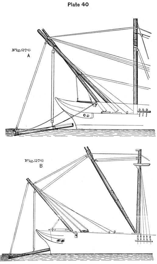
To get in the Bowsprit, Fig. 276 A, Plate 40. Transport the sheers as far forward as the bows will permit; send a hand to the sheer head, bend a girtline to the small purchase block and light it up; unlash and shift it to the forward side of the sheer head. Pass a strap around the foremast head, to which hook the double block of a large tackle; the other block take aft and set well taut. Lash a couple of large blocks to the foremast head; middle a hawser
90
and clove-hitch it around the sheer head, reeve the ends through the blocks at the foremast head, lead them aft and set them up; take aft the forward head-guys, which, with the after ones, are to be set up, and the forward belly guys to the cat-head; hook the after-shoe and heel-tackles forward and set them taut. Rake the sheers over the bows so that the main purchase will clear the billet-head.
The bowsprit is towed under the bows, with the head forward, the cap on, and the main garland lashed on a little over one-third its length out from the heel, or so that it will hang head heavy. The small garland, lash on just inside of the cap. Have guys or whips from eye-bolts in the cap to the cat-heads, and an eye-bolt in the heel for the bedding tackle which leads from the bitts on the gun-deck out through the bowsprit partners.
In getting in a bowsprit in modern vessels, the thrust of the heel, owing to the necessary lead of the purchases may be so great as to push the heel inboard too soon, before it is pointed fair for placing. To diminish the thrust and get the spar on the right slue use a fore-and-aft outrigger (stunsail yard) with one end against the neck of the strap on the lower purchase block, and the other controlled by two heel tackles.
Sway away on the main and small purchases, steadying the spar by the guys. When the heel is high enough, hook the bedding tackle. Wipe the tenon dry, and white-lead it and the mortise. Keep fast the small purchase; ease away on the main and bowse on the bedding-tackle and cat-head guys, and get the bowsprit in its place. Come up the purchases and guys, and unlash the garlands.
The bowsprit rests on the stem head, between the knight-heads, and steps in the bowsprit partners-on the gun-deck in a frigate and on the spar-deck in a sloop-of-war. It comes inboard about one-third its length. If the cap was not on, it may be shipped by means of a small pair of sheers, stepped on the bees.
If, by taking the forward head guys well aft, and setting them up, the support is found sufficient, the hawser at the sheer head may be dispensed with.
To Dismantle the Sheers. Proceed now to dismantle the sheers. Take the after heel tackles aft, come up the bulwark lashing, and rouse the heels aft, easing away the forward heel tackles, the head guys and the hawser, and lower away until the sheer heads rest on the knight-heads; strip the sheer legs, cast off the sheer head lashing and get each leg aft in the gangway; unreeve the hawser from the foremast-head and send down the single blocks. Put straps on the ends of the sheer legs and hook the fore and main pendant tackles to them, having the opposite tackles set well taut. Hook to the same straps, jiggers leading in from the channels. Pull up on the
91
tackles, rouse out by the jiggers and lower the sheer leg overboard, taking care to have skids in the proper places to prevent chafe, or the spars taking against the dead-eyes in the channels. Or, the sheer-legs may be got down by lashing their heads separately to the lower mast, casting off the cross lashing and lowering them by means of the pendant tackles.
In masting or dismasting with one's own resources, it is necessary to measure the lengths for slinging the masts very accurately, so as to make sure of carrying the heel clear of the upper deck, and yet avoid, if possible, top-heaviness. When the spars are short for the work (as in the case of the topmasts of a high ship), the masts must be slung so low as to make top-heaviness unavoidable. In going out, when the heel of the mast is near the upper-deck partners, tackles are put on above from each side of the upper-deck, and one strong and long one, led from below through the lower mast holes, is lashed to the heel, and well cleated each way. The tackles are tautened until, the heel being clear of the partners, they are eased away, and the mast lowered head foremast overboard, Fig. 274.
In coming in, the mast is slung above the balancing point and hoisted with an extra tackle alongside the sheers; the purchases are then lashed low enough down, and the heel is confined to the side by the turns of a greased hawser passed through the ports; or, in a merchant ship, through the ballast-hole. When the heel is nearly up to the highest bight, deck-tackles are lashed on from all sides, which are cleated in their place. These are tautened as the mast rises, and guy the heel, when high enough, into the mast-hole.
In handling a bowsprit with your own resources use the jibboom and spare topmast for sheer legs; or, if the fore-topmast is sent on deck, it may be used as one of the legs. The sheer head may be supported by the foretop pendants thus: Each pendant is taken through its top block at the lower mast head, thence through a top block on the upper side of each sheer head in wake of the lashing, and made fast at the foremast-head. The after ends of the pendants have the top tackles clapped on to them, led from as far aft as possible. Take the usual precautions in shoring the decks, etc. Bring the inner purchase as close in to the heel of the bowsprit as the housing permits, and the outer purchase well inside the cap. Use the spar above described to counteract the thrust in coming in. The position of the purchase blocks on the bowsprit is determined by the length of the sheer legs, which in this case would be comparatively short. The bowsprit might have to come up athwartships, when suspended, to clear the billet head. This slueing is effected by the tackle from one of the catheads; the tackle
92
from the opposite cathead will slue the spar fore and aft again when above the billet head, the heel tackle being previously hooked to assist in placing the bowsprit.
A long topgallant forecastle will make it difficult to handle the bowsprit with improvised sheers alone, as they are too short to get sufficient cant and make the main purchase clear the billet head. In that case the sheers may be assisted by a topmast used as a derrick. Fig. 276 B, Plate 40, shows such a derrick, the sheers being represented as formed of two lower yards, fished.
Vessels with long topgallant forecastles such as the "Omaha", and class, are likely to have comparatively light head booms and short bowsprits. In such cases a topmast alone, used as a derrick, might suffice to get in the bowsprit.
A neat performance in the history of Masting on one's own resources was in the case of an English line-of-battle ship, which, having lost her own mainmast, helped herself in one operation to that of a captured frigate. Sheers were formed of the main-topmasts, whose heads were supported by guys set up to the fore-topmasts, which were rigged out through the main deck ports on the off-side. A derrick was made of the main yard, which was secured at its lower quarter to the sheer leg on the working side, the pressure at this point being relieved by an athwart-ship spar, thrusting outward, by means of a tackle led across the deck. The purchase on the upper arm of the derrick took the mast out, the frigate was dropped astern, the mast lowered until the sheer purchase "looked" well up and down, when that tackle brought it in. Fig. 275, Plate 39.
Besides carrying duplicates of some of the important spars, vessels of war are supplied with iron fishes of various sizes. With these and the heavy planking, &c., furnished in the outfit, there is a large amount of material available for effecting repairs to the spars and masts when necessary, or for rigging jury masts and yards.
THE RUDDER.
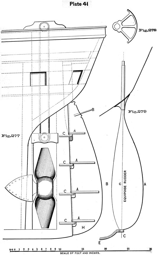
Fig. 277, Plate 41, represents the ordinary form of rudder of men-of-war. Around the pintles, A A A, the wood is removed so as to allow the rudder to ship on the gudgeons, C C C. In all but the topmost space the wood is removed so as to leave a vacant place, as shown in the figure, but by the topmost pintle the wood is cut square, as seen in the figure at d. This is in order to admit a small piece of oak under the upper pintle after the rudder has been shipped. This piece of oak is called a wood lock (d), and is intended to prevent the rudder from unshipping. Under the second
93
gudgeon a strong cleat is sometimes placed, on which the pintle partly rests. This relieves the gudgeons of much strain.
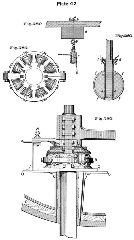
To Ship the Rudder.-First Method. Bring the rudder under the stern, hung to a scow. Bore a hole through a beam over the rudder case (i.e., the hole in the stern into which the rudder head is inserted), and drive an eye-bolt up; put a washer on and key it. In Fig. 280, a represents the key, b the washer, d the beam, F the eyebolt and E a top block. Bore a hole through the rudder head, if one is not there already, and drive an eye-bolt through and key it in the hole for the tiller. Then reeve a pendant through the top block, take it down through the rudder case and hitch it to the eye-bolt in the head of the rudder. To the thimble in the other end of the pendant hook a deck tackle. Take a hawser and make an overhand knot near the middle, reeve the hawser through the hole in the rudder H, Fig. 277, and on the side of the rudder opposite to where the overhand knot brings up make a marlinespike hitch, through which shove a toggle; make a laniard fast to this toggle long enough to reach the deck. Take the ends of the hawser forward to each gangway to act as guys; sway up, guy the rudder fair, so that the pintles are fair for entering the gudgeons, then lower away, fit the wood-lock and bolt it. Come up the purchase, unreeve the guys (hauling the toggle out by the laniard, jerking the hitch adrift and hauling the hawser through on the side of the knot), ship the tiller, reeve the wheel ropes, shackle the rudder chains, and stop up the pendants.
The tiller of a sailing vessel is shipped in a mortise in the rudder-head. Two pieces of iron, a a, Fig. 281, are put on each side of the mortise before the rudder is shipped. The pieces of iron are prevented from coming out by the two shoulders, b b. The ends, c c, of these pieces, are put through holes in the small vertical projections, d d, and are set up with nuts, e e. These pieces, called flanges or dogs, prevent the tiller from unshipping.
The band, f f f f, around the rudder-head, is of iron.
Second Method. The rudder for sailing and screw ships differs in the construction of the head; that for the latter being often shaped to receive an iron yoke, Fig. 278. Should there be no beam wherein to place the eye-bolt for the top-block, a pair of sheers, or a stout spar, lashed across the rail over the rudder-hole, may be substituted.
An improved method of securing the rudder chains, is to shackle them to the eye in the extremity of a stout iron bar projecting from the rudder as at B, Fig. 277.
During the Exploring Expedition, the rudder-head of the "Vincennes" becoming so much decayed that the tiller was useless, stout pieces of oak were bolted to the rudder on either side, so as to project similar to B. These "out-
94
riggers" were connected, by means of luffs, to spars lashed on the quarters, and the vessel steered in that way.
EQUIPOISE RUDDER.
Since the introduction of the screw-propeller and very long ships, the effort has been made to increase the water surface of the rudder with a view to an improvement in steering. The objection to some of these inventions is that the great increase of resistance brings too much strain upon the rudder-head and tiller, rendering the former liable to be twisted off. Still, where the draft is light in comparison to the length, an increase in the breadth of the rudder, over the old pattern, is indispensable.
The most successful design, so far, and one in which the difficulty just stated is overcome, seems to be the pattern known as the equipoise rudder, Fig. 279, Plate 41. In that figure, C E represents the after portion of the keel, D the screw, and A B the rudder, made of iron and working at one-third its breadth, on an iron spindle, or after-stern post c. Now, if the helm be put a-starboard, for example, then A C, two-thirds of the entire breadth, present the desired surface to the action of the water, but the strain on the tiller is diminished by the one-third, B C, which acts in conjunction with it, by the water acting on the surface from B to C.
A rudder, unprovided with the usual pintles and gudgeons, whether it be equipoise or of the ordinary type, must be fitted with some arrangement for taking its weight inboard, the spindle at the heel being merely intended to steady it.
One method of taking the weight of the rudder inboard is shown in Fig. 283, Plate 42.
The four aftermost vertical frames support a horizontal platform, O O, and a circular forging, Q, is secured to the platform, forming a table whose upper surface is beveled, as shown in the figure.
The diameter of the rudder-head is reduced so as to-receive upon it a forging, S, and to leave a shoulder above and below that forging. By means of this shoulder the weight of the rudder is transmitted by S to friction rollers underneath it, on a band, R, Fig. 282, so that the working of the rudder is rendered easy.
The after part of the forging S may be formed in such a manner as to overlap the forward edge of a locking plate, V, where, by means of a locking pin, W, the rudder can be fixed at any desired angle.
It has been found that the great area of an equipoise rudder, while adding to the maneuvering power of a vessel under steam, tends to destroy her way when tacking, causes
95
her to miss stays, &c. Equipoise rudders have, therefore, been designed where the fore part may be locked in its amidship position, leaving the after part alone to act in steering the ship when under sail.
Back-Chains. It is frequently necessary for steamers to back against the helm, but in doing so the strain brought on the rudder and its fitments is immense.
Tug-boats guard against such accidents by using back-chains. These are chain pendants which attach to the after-part of the rudder and to some point under the counter, one each side, and of such a length as to give ample support to the rudder when backing with the helm hard over.
Instead of these chain pendants, many tugs and small steam craft have chocks bolted to the rudder-post on each side, and of such shape as to limit the motion of the rudder to an angle of 45° in either direction.
CHAPTER VIII.
STANDING RIGGING.*
The rigging of a ship consists of a quantity of ropes for the support of the masts, yards and booms.
Each mast is supported from forward by stays, from aft by backstays, and sideways by shrouds. The foremast is supported in a great measure from the bowsprit, therefore the bowsprit has a number of extra stays, called bobstays. These, and such ropes as are stationary, constitute the standing rigging.
The standing rigging of modern vessels is composed of wire rope, iron wire rope being in general use, although the substitution of steel wire, owing to its greater strength and lightness, can only be a question of time.
Wire rope now in use in the U. S. Navy for standing rigging, is right-handed, of six strands, each strand having an untarred hemp heart, and another heart in the centre of the rope. The individual wires forming the strand are of a size (larger or smaller) corresponding to the full size of the rope.
In the Navy, all wire rope is measured and designated by its circumference, but bridge builders, and others than seamen, often use the diameter to designate the size of wire rope.
Wire rope is reeled for stowage or transportation on strong wooden reels. To take wire rope off a reel, cast loose the outside end, which is secured to the reel, and make it fast to a bolt in the floor or deck. Place the reel on its edges, with the rope end underneath, roll the reel along the floor to a point a little beyond the length required, then clap on a strap and tackle near the reel, leaving enough space between the strap and the secured end to measure off the required length. Haul the rope taut along the floor, place a mark close up to the secured end. Then measure off from the mark at end the number of feet and inches required. Make allowance for end enough to work either for splice or to turn up, and place within an inch of each other two strong bindings or whippings to keep the ends of wire in place when it is sawed off.
* For much of the information concerning wire rigging, our Thanks are due to Boatswain John A. Brisco, U. S. N.
97
If the wire is to be served the full length, it would be better to get it on a stretch before cutting, but if the ends are to be spliced into eyes, then with a hack-saw, kept well oiled, saw the wire in two between the whippings, secure the end of the rope to the reel and put it away.
Should it be required to take all the wire from the reel, then the reel will be rolled as far as circumstances admit, back and forth, till all the rope is off. The rope can then be taken up and put on stretch just as it lies upon the floor without taking turns out for stretching.
A piece of 3/4-inch iron chain, about 3 feet long, with a ring in each end, one ring sufficiently large to let the other reeve through it, is the best strap to be used in putting heavy wire rope on a stretch. Plenty of protection should be put on the rope to prevent the chain from injuring the wire. To apply the chain strap, pass a turn around the rope with one end of the strap, and pass the other end through the ring, and jamb it into place by hand. If it is to be a very heavy pull, a half-hitch can be taken, hook on to the unconfined end and heave taut.
Wire rope, not galvanized, is best protected from weather and wear if painted with boiled linseed oil and red lead, well mixed, and filled well into the lays, wormed and parcelled with cotton sheeting, so cut and laid on that the overlapping will give two thicknesses over all the rope, then painted again and served tight and close over all. If properly done, this will keep out water for years.
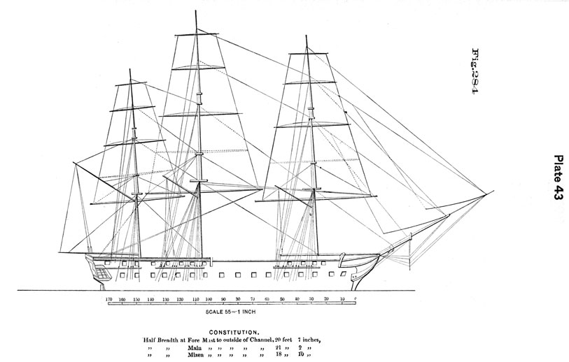
Cutting Ribbing by Draft. Having an accurate draft of the hull and spars of a ship, Fig. 284, Plate 43, the measures may be readily taken and the rigging cut and fitted so that it can be sent aloft as soon as the masts are ready to receive it. It not unfrequently happens that a gang of rigging is completed and triced up out of the way, in the rigging loft, long before the ship is ready to take it.
Rigging drafts are usually made on an 1/8-inch scale (one-eighth inch-one foot). This scale is most convenient, because the ordinary two-foot rule can be used as well as any more complicated measure, and the drawing made on an eighth scale is of a convenient size. The largest ship will require a sheet of paper not more than 2 1/2 feet by 3 feet.
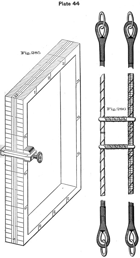
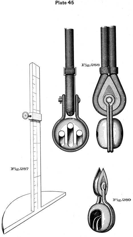
The half beam at each mast is usually noted on the draft at the respective channels, but the location of dead-eyes seldom, and therefore the rigger must get the measurements from the vessel. As no beam draft is now furnished, an adjustable beam scale, Fig. 287, Plate 45, is employed (which is graduated to the same scale as is the draft) with a sliding rest and set screw. Another adjustable beam scale, Fig. 285, is in the form of a hollow square of metal, graduated on its four exterior sides to different fractional parts of an inch. The sliding rest for the point of the dividers may be applied
7
98
to any one of the four sides to correspond with the scale used in the draft.
Before working on the draft scale, measure carefully the square of the mast-head just in line with the upper side of bolster. The measure of the square is used to fit the pendants, but for eyes of the lower rigging, five square of the actual girth measure is used. The mast-heads are rounded for wire rigging, iron or composition plates being let in and secured on each corner of the mast-head to round it off.
Lower Mast-head Pendants. Should be fitted long enough to hang one foot below the futtock band, and both legs are now fitted the same length, with an iron thimble and large link in each end. Fig. 286, Plate 44. The thimble is usually spliced in as close as possible, and for a time it is neat and answers well, but when the service becomes rotten or worn, and requires repairing, the splice is liable to injury in removing the thimble. It would be better to fit the ends with a long eye, so that the thimble can be moved in repairing, and secured in place by a good. seizing. In measuring for lower mast-head pendants, find the distance from top of trestle-tree to one foot below futtock band, add one thickness of trestle-tree, and half square of mast-head, which, doubled, will be the combined length of starboard and port leg; add the half length of the round of thimble or length of eye, and a due allowance of end for splicing. Now paint worm, parcel, paint again and. serve, and double serve with spun-yarn in the place required for the thimble, splice in the thimble, tucking once whole, once two-thirds, and once one-third. Hammer the splice into a smooth taper, and get the pendant on a stretch by hooking tackles into the links; break off the wire ends close into the lays, give the pendant a good painting, worm from and parcel toward, the centre, serve with spun-yarn, and double serve from centre to a distance equal to one-half the mast-head, together with the thickness and depth of trestle-tree.
With tarred flax parcelling head up from nearly the end of the double service to the centre, and marl on with strong marline, the hitches not more than half an inch apart, being careful to leave a space without hitches at the mark for the cross-lashing, which is to be ascertained and marked before the marling is put on. Having the two pendants spliced, served, headed up and carefully marked for the cross-lashing, let down. From the centre mark of each pendant, lay off and mark each way one half the square of the masthead. Take two pieces of wood about three inches wide and one inch thick, equal in length to one square of masthead, lay the two pendants side by side to verify the marks, then spread them apart till the pieces of wood can be placed across and from pendant to pendant, just outside the marks
99
where the cross-lashing is to go, allowing room to comfortably work the lashing. With a piece of strong seizing stuff with a long eye, proceed to put on a regular round seizing from pendant to pendant, being careful to keep outside of the mark, or the square will be too small to go over the mast-head. Having passed the riding turns of the lashing, secure its end. Then around the cross-lashing close up to the pendants put a good seizing of houseline, being careful to bring all parts of the cross-lashing close together, and marl the lashing together, parcel with thin stuff and woold with a strand, then with tarred flax parcelling protect the lashing, cover well the turns around the pendants and marl all down. Leave the wooden strips in till the pendants are about to be put over the mast-head.
A link is put into the end of the pendant because it is so much easier hooked into than the thimble in the stiff wire, alone.
The mizzen pendants being made of smaller rope than the fore and main, can be fitted in the same manner, excepting where they are fitted with a cut splice or spanned to a pair of odd shrouds, as is sometimes the case. When pendants are to be fitted in the latter way, the same rules hold good, for the odd shroud and pendants spanned together go on the mast-head first. The odd shroud is fitted straight and passes over the bolsters from side to side abaft, as if it were an after-pendant, and the span is fitted as above described for double pendants. In small vessels, and when there is no odd shroud, the mizzen pendants are fitted with a cut splice, the cut eye to be one foot longer at each end than the eye for a shroud, with good seizings at the proper places. The eyes are purposely made too large to prevent injury to the splice in opening the eye.
To Measure for No. 1, or First Pair of Shrouds. These comprise the swifter and next shroud, or, as called by riggers, "forward leg" and "after leg," and they go over the mast-head next after the pendants and always on the starboard side.
The beam-scale, Figs. 285 or 287, being adjusted to the mark representing the half-beam of the vessel, minus half the diameter of the mast, place it on the draft just at the upper edge of channel at the dead-eye of the first shroud. Place one point of the dividers at the top line of trestle-tree near the forward side of mast-head and the other point on the beam-scale at the mark indicating the half-beam, apply the dividers to the rule and observe the number of feet and inches it gives according to the scale on which the draft is made; this will give the length of the forward shroud, or "forward leg," of No. 1 pair, without the eye. Then proceed to measure for the next shroud or after-leg in the same manner, moving the beam-scale to the second dead-eye. There will be very little difference in the length of the two
100
first legs, and if any, the after leg will be a little shorter on account of the rake in the mast and the shroud being more perpendicular. Having the length of both legs of No. 1 pair of shrouds, take their sum and add five squares of the girth-measure of the mast-head, plus the diameter of the lower mast-head pendants, as the shrouds will "pile," or rise, that much on the mast-head. This will give the extreme length of No. 1 pair.
Having the rope on a stretch, hang it, with tricing lines at short intervals to prevent sagging. Commence measuring from a mark near the strap on the end, the length of the forward leg. Then continue along to measure five square of mast-head, being careful to leave at the centre (which will be the centre of eye) a special mark, usually a long strand. Then measure and mark the after-leg, and in the same manner measure and mark all the other shrouds, not forgetting to add for the second pair of shrouds twice the diameter of a finished eye; for the third pair three times the diameter, &c., as each succeeding shroud must "pile" that much in rising above the others on the mast-head. The first pair of shrouds, or No. 1, being on stretch, measured and marked, worm it and paint from end to end with red lead and boiled oil, being particular to fill well in the lay. Over the worming parcel with new cotton sheeting. In putting on this parcelling commence from the end of each leg, working towards the centre of eye. The parcelling should be so put on that the rope will be protected with two thicknesses at every point; now paint again over the parcelling, and serve from end to end with spun yarn, commencing to serve from the centre and serving in the opposite way to which the parcelling was put on. Measure off from the centre mark each way the half eye (the half of the five square), which gives the place for the upper turn of the eye seizing. Start two feet below these eye-seizing marks, on each leg, and parcel with tarred flax canvas to the centre of eye, and serve over with roundline. Double serve the end of each shroud from the place of the quarter-seizing for its dead-eye. Now let down the shroud and saw off; bring the two ends together and break the eye around till the two eye-seizing marks come firmly together. Mark one foot below the eye-seizing on each leg, and with strong flax parcelling put on the heading, which is just the same as parcelling, always commencing below and working up to the centre on both legs so that the edge of the "heading" will overlap and form a "shingling," which it is often termed. Use the selvage edge of parcelling stuff for shingling, leaving the selvage out; this makes smooth work that will not fray out. Secure the heading in place by marline hitches, which should be on top not more than one-half inch apart, leaving a space for the eye-seizing without hitches.
101
Should there be an odd shroud in the fore or main rigging, it is fitted with an eye-splice, and goes over the masthead last, the eye to be spliced one foot longer than the eye of a pair of shrouds, and seized together above the splice so as to have the same size as it would have if of a pair; the eye to be double served and headed in the same manner as all the others.
Mizzen Rigging is fitted in the same manner as the fore and main, excepting in the case of an odd shroud, which is fitted "straight," passing over across the masthead abaft and forming one leg on each side, being spanned at the mast-head with the pendants, of which the mizzen has in this case but one on each side. In large ships the mizzen lower mast-head pendants are often fitted with four legs, in the same manner as is the fore and main.
Sword mats are substituted for service on the swifters (forward shrouds) of lower rigging.
Bowsprit Rigging. Bobstays are now made of iron chain shackled into the cutwater and set up with four score hearts. To find the length of bobstays, measure from the band under the bowsprit at the place prepared for the upper heart, to the bolt or link in cutwater, then find the number of feet and inches the two hearts will occupy and the drift of laniard, add together and subtract the sum from the extreme length; the remainder will be the length of the chains required for the bobstay. Care should be taken that the bobstays have the same drift of laniard, as it adds to the trimness of the head gear.
Bowsprit Shrouds are fitted of wire and lead well down on the bows, shackled to eye-bolts and set up with three scored hearts. To find the length by draft, measure from the band on bowsprit at the place marked to the place in the bow, and from the extreme measure deduct the drift of laniard and one heart. The reason of but one heart being deducted, is that the measure of the other allows for the "carry out" of the shroud. Too much care cannot be taken in fitting the gear and securing the bowsprit, as it not only has all the head booms to support, but in a great measure the foremast with its topmast and topgallant mast, together with the main topmast and topgallant mast.
Fore Stays are fitted with lashing eye collars and set up with laniards and four score hearts. Measure for fore stays from the after-side of foremast head, about one foot above the trestle-trees, to the place where the lower heart is to be.
To form the collar of the stay, allow, in cutting, for twice the length of the intended collar.
When cut, unlay one-half (three) of the strands to the mark for the crotch of the collar, keeping each set of strands together. One of the sets will contain the
102
heart. A heart must be laid in with the other three strands.
Form the eye in each leg of the collar by turning back the strands and working two of them down to the crotch. The third strand of each set is spliced around the eye and the surplus end cut off.
We then have each leg formed of five strands; each eye formed of three strands.
The length of the collar is usually equal to the length of the mast-head, but may be reduced if necessary to keep the fore yard, when sharp up, from taking against the collar.
Paint, worm, parcel and serve with spun-yarn, parcel again with flax, and double serve with round-line; fid out each eye and insert a strong hard-wood toggle. Get the stay on stretch by lashing the toggles to posts four or five feet apart, get a strong tackle on the end, heave it up straight and trim the splices. Paint, worm, parcel, paint again, and serve with spun-yarn from end to end, being careful to have a good piece of parcelling laid through the crotch to shed the water. Then, from four feet below the crotch, parcel with tarred flax parcelling to eyes of collar, and leather over the parcelling, serving over the ends of the leather and over the splices. Having both stays double served and leathered, place one over the other, being careful to keep the crotches fair and even. Then seize both stays together with one good heavy seizing close up to the crotch, and smaller ones at every two feet along the collars. Parcel and leather over the seizings. Double serve the ends of fore stays to eight feet above the nip around the thimble.
Main Stays are fitted in the same manner as fore stays, excepting the double service on end, which is only from quarter seizing around thimble to end. Sometimes if the smoke-stack, when up, is near the stays, a piece of chain is shackled into the stay just over the stack. The main stays generally set up with four scored hearts, the lower heart being secured to iron straps made for the purpose, one on each side of the foremast. The iron rods or straps lead down to the berth deck, frequently passing through the bitt standards and setting up with a nut on the forward side.
Mizzen Stays are always single, with the collars fitted and lashed, same as fore or main stays. On some vessels the end is split into two legs to admit the main trysail mast, and each leg fitted with a thimble to set up by laniard to bolts on each side of main-mast. On others the end is turned up around a thimble and set up with three score hearts to the after-side of main-mast.
The ends of all stays turn up under the standing parts.
The ends of all shrouds turn up inside the standing parts.
Futtock Shrouds are made of rod iron set up with turn-buckles. The required lengths are best obtained
103
by actual measurement after the top is on. In small ships futtock shrouds are rattled down. Futtock shrouds are set up independently to the top rim, and not to the plates of the topmast dead-eyes. The lower ends secure to the futtock band.
NOTE.-In the above measurements for shrouds it is assumed that by measuring from the place of the lower dead-eye, on the channel, enough allowance is made for turning up the shroud around the thimble of the upper dead-eye. But if the drift of the laniard added to the diameter of both dead-eyes does not allow enough shroud to turn up, extra length must be added for that purpose to each measurement taken.
The amount allowed for turning up is six feet for the forward shroud of large rigging, a proportionately smaller amount for smaller rope. After shrouds have somewhat more turn up than forward ones, in order to bring the ends themselves parallel to the sheer.
Upper dead-eyes are usually in line with or below the rail.
When lower rigging has been set up for some time, or after a ship has experienced heavy weather, it will be found that the shrouds will not lie exactly above one another, but settle, the necks of the eyes working partly inside of each other. The effect is to slacken the rigging, particularly the after shrouds, which settle most, and which may require turning in again to keep the dead-eyes in line, a difficult operation with wire rope. If the allowance for piling were two-thirds of a diameter of the shrouds, instead of a whole diameter, as at present, it is believed that much of this inconvenience could be avoided, although a few of the after dead-eyes might not come quite to their places when the shrouds are first set up.
Topmast Rigging. To measure for topmast shrouds from the scale draft, proceed on the same principle as for lower shrouds. Set the beam scale to one-half the spread of the top from the side of the mast, allowing for the rounding of the top; place the beam scale on the draft abreast of the proper dead-eye, and measure the distance with dividers from the top of the sliding rest to the top of the trestle-tree. Add for each pair the spread of the trestle-trees, and make the usual allowance for turning up from the nip of the dead-eye thimble.
Topmast rigging is fitted in the manner known as "straight," with one eye formed out of two pairs of shrouds, which gives two "lifts" or thicknesses on the mast-head, with four shrouds on each side, making a snug and neat mast-head.*
* This answers very well for ships intended to do most of their cruising under steam; but cannot be recommended when sail is to be carried to any extent. All the strain comes on the seizing.
104
It should be painted, wormed, parcelled, painted again, and served the entire length. The shrouds double served from centre of eye to three or four feet below the futtock-staff. The length of heading from centre of eye down to one foot below the eye-seizing is put on the same as for the lower rigging.
Catharpins are of wire rope, wormed, painted, and parcelled, and double served throughout; fitted with eyes in each end, and go abaft the mast and seize together in the centre.
The topmast-head (burton) pendants are wire rope, fitted with a shackle in one end and a link in the other; the shackle connecting to a link under the trestle-trees. Each topmast has four pendants, two forward, and two abaft the rigging. The lower ends of pendants hang six inches below the catharpin legs.
Pendants are fitted the same as topmast rigging, without double service, except around their thimbles.
Sword mats are substituted for double service on the swifters of topmast rigging.
Topgallant Shrouds. The easiest way to measure for length of topgallant shrouds is to draw a figure to scale, showing the top, the position of the futtock-staff, and position and spread of cross-tree. Measure on that draft from the topgallant mast-head to the horn of the cross-tree, thence to futtock-staff and into the top, where the shroud sets up. Allow for each pair enough for a neat eye around the funnel, and ends for turning up.
The shrouds are painted, wormed, parcelled, painted again, and served the entire length, and go over the funnel on the mast-head. They are fitted in pairs, with eyes formed like the eyes of lower rigging, and seized so as to fit snug over the funnel.
The forward legs are double served from the centre of eye to one foot below the futtock-staff of topmast rigging; the after leg is double served from centre of eye, three feet down; then from a point one foot above cross-trees to one foot below the futtock-staff: both legs are leathered in the wake of cross-trees, and set up in the top with dead-eyes.
Royal Shrouds, Stays and Backstays. Measure for each to where it leads and sets up, allowing enough end to turn up in the wake of the thimble.
Fore.-Are painted, wormed, parcelled, painted again, and served the entire length, and fitted to an iron funnel or band, which has three eyes at equal distances apart, one on each side and one forward. The shroud and backstay are one piece, rove through a side eye of the band and seized around a thimble there. Double service one foot down on the shroud and backstay from centre of eye, double service on the shroud, leathered in the nip of the jack. The stay is spliced around a thimble on the forward eye of the band
105
double served and leathered in the nip of the flying jibboom, in the clamp on the dolphin striker, and also where it reeves through the bees on the bowsprit.
Royal shrouds set up in the top with a purchase; stays and backstays with dead-eyes.
Main.-Fitted and set up the same as the fore; double service and leathered at the nip of the chock in the fore-topmast trestle-trees.
Mizzen.-Fitted and set up the same as the main; double service and leathered at the nip of the chock in the main-topmast cross-trees.
Fore-topmast Stays. Measure from after part of topmast-head to the bees, thence to place of setting up; make allowance for turning up. They are fitted separate; single service throughout; collars the same as fore and main; double service from ten feet above the bowsprit to one foot inside of the leader under the bees; leathered over double service from four feet above the bees to eight inches inside the leader, under the bees. Set up with three-scored hearts.
The service on the port (spring) stay is omitted in the wake of the stay-sail hanks.
Jib Stay. Measure from after part of topmast-head to where it leads and sets up. To be fitted like fore-topmast stays, with split collars, lashing-eyes, &c.; served from four feet above the boom to the end where it sets up; double service and leathered in the nip of the clamp on the dolphin-striker, and also where it goes through the bees, leathered over the surface from four feet above to eight inches below the boom; collars of jib and topmast stays seized together below the crotch around the stays, seizings parcelled and leathered. Set up with three-scored hearts.
Main-topmast Stays. Measure and fittings similar to fore-topmast stays; in long ships, with great distances between fore and main masts, they may be brought directly to the deck near the foremast;* but in short ships they pass through chocks between the fore trestle-trees, and. set up on deck with three-scored hearts. Nips double served and leathered; collars seized together in the loft.
Mizzen-topmast Stay. Measure and fittings similar to main-topmast stays, and set up in the main-top with three-scored hearts.
Fore-topgallant Stay. Measure to where it leads and sets up, allowing for neat eye-splice around funnel. Painted, wormed, parcelled, painted again, and served the entire length; double served on the eye around the funnel, and from twelve feet above to one foot below the jib-boom; also in the wake of the nip of the clamp on the dolphin-
* It would be better if this lead could be adopted in all ships, but the smokestack frequently interferes.
106
striker, and where it reeves through the bees, or leader under the bees. All nips to be leathered. Stay set up with dead-eyes.
Main-topgallant Stay. Measure and fit like the fore, and set up with dead-eyes in the fore-top. Double served and leathered at the hole in the fore-cap through which it leads, also leathered about three feet below the crotch of the eye-splice.
Mizzen-topgallant Stay. Measure and fit as above. Served, leathered, and led through a hole in the main-cap and set up in the main-top.
Flying-Jib Stay. Measure and fit with an eye-splice, similar to topgallant stay. Double served; served and leathered three feet below the crotch of splice, in all other respects fitted like the jib stays. Set up with dead-eyes.
Jib Guys are of wire rope, painted, wormed, parcelled, painted again, and served the entire length; double served and leathered in the wake of whiskers, over which they fit with horseshoe cringles; outer ends shackle to a band on the boom end; set up to the bows, or cat-head, with three-scored hearts.
Flying-Jib Guys are of wire rope, fitted, set up to the bows, or cat-head, with three-scored hearts, and connected with the boom, same as jib guys; reeve through thimbles in a strap out on the whisker yard-arms. Double served and leathered in the nip of the thimbles.
Whisker-Jumpers are of wire rope; painted, wormed, parcelled, painted again, and served throughout; fitted with an eye-splice, double served and leathered, to fit over the whisker-boom end; the inner end leathered in the nip, and set up on its own part through a bull's eye connected to a bolt on the cut-water.
Back Ropes are fitted of hemp, served throughout, hooked or shackled to the dolphin-striker, and set up at the bows with three-scored hearts.
Jib Martingale-Stay is of wire rope, wormed, parcelled, and served the same as guys. Fitted with shackles and thimbles in each end, with double service around the thimbles. Shackles to the dolphin striker and to the band on jib-boom.
Flying-Jib Martingale-Stay. Fitted the same as the jib martingale, of wire; double served around the thimbles in the outer in the wake of the sheave on the dolphin-striker, and where it reeves through the bees, or leader. Sets up with dead-eyes.
Fore and Main Topmast Backstays. Fitted and measured off the same as the after-shrouds of the fore and main rigging.
Mizzen-Topmast Backstays are fitted with horseshoe eyes, or, properly speaking, a span. Measured like the fore and main.
107
Fore, Main, and Mizzen Topgallant Backstays are painted, wormed, parcelled, painted again, and served throughout. Fitted with spliced eyes, which are double served, without outside parcelling. Measured from the funnel to the place of setting up in the channels, with allowance for the eye and the usual allowance for turning up.
For the rules for finding size of shrouds, see Appendix C.
Boat-Davit Topping Lifts, Spans and Guys, are of wire rope, and served throughout. Spans to which topping-lift pendants are attached are leathered in the middle.
Dead-Eyes. The dead-eye now used in the Navy is shown in Fig. 288. Plate 45.
The end of the shroud passes around a heavy iron thimble, which is confined by a pin to the lugs of the iron strap of the upper dead-eye.
Dead-eyes are made with one hole without a score on the inboard face, the edge being left square so as to present a solid shoulder to the knot of the laniard.
The shroud being passed around the thimble is secured by five seizings-throat, quarter, middle, upper and end seizing.
The two lower turns of the throat seizing are racking turns, over these come riding turns. The seizing is crossed and hitched in the upper part.
The quarter, middle and upper seizings are riding seizings.
The end seizing is flat, crossed and hitched, and holds into place the canvas cap placed over the ends of all standing rigging.
Lower dead-eyes connect with the chain plates by bolts, so as to be readily unshipped. The bolts are fitted with forelocks.
In setting up stays and some other portions of the standing rigging, scored hearts are used instead of deadeyes. These hearts have iron straps, and the upper ones are supplied with iron thimbles similar to those around which a shroud is taken. Fig. 289, Plate 45.
Care must be taken in turning the ends of shrouds or stays around their thimbles that it is done properly, as, in the event of a change becoming necessary, it is difficult to get the old nip out of the wire.
All wire rigging in the Navy sets up with hemp laniards, which impart all the "give" necessary.
Topmast rigging of fore and aft vessels may be set up on end.
For turning in old-fashioned dead-eye, see Appendix C.
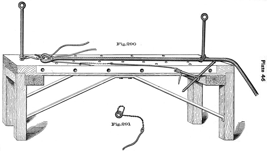
The Splicing Bench, Fig. 290, Plate 46. For convenience in handling wire rope, some rigging lofts are supplied with splicing benches, which are large tables of hard wood, plated with iron on the top and sides.
108
The top of the bench is pierced with holes, into which may be set steel standards or "normans," by which the rope is steadied on a stretch. Similar holes are made in the sides of the table to receive smaller pins.
In splicing, for instance, a link and thimble into a large wire rope, the rope itself is steadied between two normans at opposite ends of the bench. A hook, fitted with a ring which slips over the norman head, is hooked into the link of the thimble around which the rope is to be spliced.
When a strand has been stuck once, a small chain strap, Fig. 291, Plate 46, with a ring in the chain end and tailed with manilla rope, is clapped on to the strand. The strap leads off to the side of the bench in the direction to be taken by the strand. The rope end of the strap is there taken around one of the projecting pins and hove upon, by converting the pin into a Spanish windlass.
A like purchase is used on every strand after sticking, varying only the lead of the strap. As the sides and top of the bench are pierced with suitable holes, the lead of the strap can be changed in a moment by shifting the position of the pin used.
In Fig. 290, some strands are omitted to avoid confusion.
A turning in machine for wire rope, Fig. 292, Plate 47, is supplied in rigging lofts and aboard ships to shape wire rope when turning in thimbles, or wherever it is required to make a short nip.
In splicing wire rope proceed as with hemp, sticking once whole, once two-thirds, and once one-third; get it on a good stretch and break off the wires close to the rope by working them quickly backwards and forwards.
In splicing an eye with more than three strands, the second left-hand strand is tucked from right to left under the first convenient strand.
Take the precaution when the marlinespike is entered under the strands where you wish to put in the first tuck, to beat the strands on either side of the spike with a hammer, so as to keep them open until the strand is entered.
To splice a thimble in wire rope. Red lead, parcel and serve the rope in wake of the thimble. Break the rope around the thimble, stop the parts together, pass seizings around the rope and through the thimble to hold the latter in place. Then open out and splice.
Besides the marlinespike; pincers, files, cold chisels and saws are useful in the manipulation of wire rope.
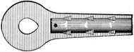
Metallic Splices. A new method of splicing wire rope is being introduced by which the end of the wire rope is inserted into a metallic socket and there secured by pouring a strong fusible metal around it, filling all the spaces in and around the rope, and forming a solid and firmly united structure.
109
The sockets may be terminated by any kind of device commonly used in connection with wire rope. A round-eye socket is used to replace the eye-splice around a thimble, and similarly sockets with bull's-eyes, sister-hooks, or deadeyes are made for use in connection with this process of splicing.
In the figure is shown a longitudinal section of a round eye socket, showing an arrangement of inside notches into which the filling metal sets, increasing the strength and safety of the splice.
This method of splicing has been favorably reported upon, the results of tests showing that the patent splice is stronger than the common splice, and stronger than the rope itself; also that it is durable, more quickly and economically made, and that it presents a neater appearance.
To make the Metallic Splice.
First, Measure the depth of socket and cut the same length from the hemp heart of the rope.
Second, Have a sufficient quantity of filling metal being melted.
Third, Insert the end of rope into the socket, and hold it in a horizontal position over a strong heat until a piece of the filling metal will melt when held on the upper side of socket, and until the rope becomes too hot for the hand at three inches distance from the socket. Have the filling metal hot enough to ignite a shaving or piece of paper when brought in contact with it.
Fourth, Place the splice with the rope inserted in an upright position and pour the socket full, and let it remain in position until cool, when it is ready for use.
The Kind of Filling to Use. Pure tin, or a compound of half lead and half tin, or the latter compound with two per cent. of antimony added.
The following tests of the metallic splice were made at the Watertown Arsenal, August 22, 1881:
SOCKETS
STEEL WIRE ROPE
ULTIMATE STRENGTH.
Malleable Iron
Two inch
20,900 lbs.
"
Three inch
45,700 lbs.
"
Four inch
73,000 lbs.
The rope was broken in every case and the splices were uninjured.