In this online version of the manual we have attempted to keep the flavor of the original layout while taking advantage
of the Web's universal accessibility. Different browsers and fonts will cause
the text to move, but the text will remain roughly where it is in the original
manual. We have not attempted to correct any errors found in the original document. However, this text was captured by optical character recognition and then encoded for the Web which has added new errors we wish to correct.
I apologize for the uneven photographs of the plates. The change notices on page iii are illegible, and the bottom of page 23E is covered by change notice. Please report any typos, or particularly annoying layout issues with the Mail Feedback Form for correction.
Richard Pekelney
Webmaster
CONFIDENTIAL
This book is the property of H.M. Government.
It is intended for the use of the Officers generally and may, in certain cases, be communicated to persons in H.M. Service below the rank of Commissioned Officer who may require to be acquainted with its contents in the course of their duties. The Officers exercising this power will be held responsible that such information is parted with due caution and reserve.
CONFIDENTIAL
Attention is called to the penalties attaching to any infraction of the Official Secrets Acts.
C.B. 4112 B.R. 1634(8)(45)
HANDBOOK
ON THE
USE OF RADAR FOR
GUNNER PURPOSES
VISUAL/RADAR
TARGET INDICATION
1945
ADMIRALTY, S.W. 1
GUNNERY BRANCH
Illegible revision history.
iii
ADMIRALTY, S.W.1.
17th October, 1945.
G.05997/45.
C.B. 4112(8)(45)-Handbook on the Use of Radar for Gunnery Purposes, Visual/Radar
Target Indication, 1945, having been approved by My Lords Commissioners of the Admiralty,
is promulgated for information and guidance.
This book should be inserted in C.B.4112 (G.B. and I.)-Guardbook and Index for Handbook
on the Use of Radar for Gunnery Purposes.
C.B. 4112(8)-Handbook on the Use of Radar for Gunnery Purposes, Visual/Radar Target Indication, 1944-is hereby superseded and all copies should be destroyed in accordance with Article 42, B.R. U.2.D. (1945).
By Command of Their Lordships,
To Flag Officers and Commanding
Officers of H.M. Ships concerned.
(C50071) B2
iv
CONTENTS
Foreword
Paragraph
CHAPTER I
Introduction
General Objects of the T.I.U. How the Objects are Attained Where the T.I.U. is Fitted Limitations Accuracy Performance I.F.F. Communications Other Publications
1-29
Page iv, CONTENTS, Introduction. Delete and substitute:
General-Objects of the T.I.U.-How the Objects are Attained-Where the T.I.U. is Fitted-Limitations-Accuracy -Performance - I.F.F. -Communications -Other Publications-Armament Broadcast System
Description of T.I.U Marks IIA and IIB
The T.P.I.-Working Controls-The T.I.U. Box-Principle of Operation of the T.I.U. Box-Description of the T.I.U. Box-Sector Selector Switch-Interrogator Aerial Transmitter Drive-The Projector Unit and Optical System-Ranging Outfit R.T.B.-R.T.U. 53-Indicator Outfit J.H.I. (I.F.F. Panel 43)-Close Range Armament
PART II-Battleships, Cruisers, Aircraft Carriers-A.A. Target Indication.
Selection of Target Indicating Position-Target Indication by the A.D.O.-Target Indication by the P.C.O.-Target Indication by the T.I.O.-Target Indication for Close Range Weapons by T.I.O.
PART III-Battleships, Cruisers, Aircraft Carriers-Surface Target Indication.
Target Selection-Surface Target Indication by the T.I.O.-Separate Main Armament Target Indication in Battleships and Cruisers-Duties of Gunnery Liaison Officer (G.L.O.)-Use of Starshell-Positions for Target Indication Switches
PART V-Setting-up Details.
Initial Setting up of the T.P.I.-Centring the Trace-Adjusting the Pre-set Controls Setting up the Trace-Lining-up the T.P.I.
Adjustments and Tests
Erection Adjustments and Tests-Lining-up and Checking when Closing up-Checking Connection of Aerial Repeater Motor-Checking Connection of Compass Repeater Motor-Lining-up of the T.I.U.-Workshop Lining up-Installation Lining-up on board and Adjustment of the Optical System-Magslip Alignment-Sectoring Switch Alignment-Sectoring Switch Adjustment-Hunter Adjustment-Procedure for Dismantling a T.I.U.
Appendix-I-Functions and Positions of Target Indication Change-over Switches ("Battle" Class Destroyers; not applicable to Leaders)
23
Appendix H-Coverage Diagrams for A.U.J., A.U.R., A.Q.R.
APPENDICES. Delete and substitute:-
Appendix I.-Functions and Positions of Target Indication Change-over Switches ("Battle" Class Destroyers; not applicable to Leaders)
Appendix V.-In Destroyers and Small Ships. Action Information Intercommunication System. Armament Broadcast System. Action Intercommunication System. Radar Reporting Line. Requirements of Microphones and Speakers
An essential prelude to the consideration of the subject of Visual/Radar Target Indication
is a thorough understanding, by officers and men concerned, of the capabilities of the various
types of Radar and associated equipment. These have been specially adapted to meet the
various requirements of different ships and it will thus be possible to have many combinations
of Radar equipment.
A short précis of the equipment most likely to be encountered is appended and this will
enable the reader to obtain a clear picture of the functions and the limitations of the equipment.
Radar Sets
W.S. Type 276.-This set has been developed from Types 271/273 and is much more
powerful. It provides continuous all-round warning of surface targets and will detect low flying
aircraft but not high flying aircraft. The aerial, which normally rotates continuously, is
stabilised in azimuth, and has a beam which at half amplitude is roughly 6 degs. wide in the
horizontal plane and 20 degs. in the vertical plane with a reliable range of 25,000 yards on aircraft. This set may be fitted to work with the T.I.U. for target indication purposes at low
angles of sight.
Note.-All Type 276s in service are being converted to Type 293/M.
W.C. Types 293 and 293/M.-These sets are also developments of Types 271/3, being
Type 276 with different aerial arrays. They provide continuous all-round warning of surface
and aircraft targets, but the surface cover is not as good as with Type 276, this being reduced
to enable the sets to detect high flying aircraft. The aerials, which normally rotate continuously, are stabilised in azimuth and have beams which at half amplitude are roughly
5 degs. wide in the horizontal plane, 65 degs. in the vertical plane for Type 293, and
45 degs. in the vertical plane for Type 293/M. They have reliable ranges on aircraft of at
least 15,000 yards and 18,000 yards respectively. The normal function of these sets is target
indication in conjunction with the T.I.U. and Target Position Indicator (T.P.I.). In small
ships and carriers they combine T.I. and tactical warning purposes.
W.C. Type 293P.-An improved 293 set will soon be available for fitting in certain ships.
This set will incorporate modifications which will give it improved performance over Type
293/M with a greater reliability.
W.S. Type 277.-This set is also a development of the Type 271/273 marque. It provides
continuous all-round warning of surface and low flying aircraft targets with provision for
measuring angle of sight. The aerial, which normally rotates continuously, is stabilised in
azimuth and in the vertical plane, and has a narrow beam which at half amplitude is roughly
6 degs. wide in the horizontal plane and 6 degs. in the vertical plane with a maximum reliable
range of 80,000 yards on aircraft. The angle of sight is measured by elevating and depressing
the aerial (which has to be stopped rotating) and is shown directly on a Height Position
Indicator (H.P.I.).
W.C.H. Types 980/1.-This is a F.D. (Fighter Direction) set, still under development. It
is intended to give good all-round continuous warning and accurate height finding. It will
only be fitted in carriers.
W.A. Types 79B and 281B/BM.-These sets are the original high-powered air warning
sets converted for use with one mast only. Type 79B aerials are hand controlled and
281B/BM aerials power driven. Ranges up to 100 miles can be obtained on high flying aircraft
but the low flying cover is not reliable. Types 281B/BM can work in conjunction with P.P.I.s
and Skiatrons but arrangements are not normally made for it to work with T.P.I.s.
Fitting Out Policy
It is intended, when fitting out is complete, that ships should have the following Radar
warning sets for the functions shown:-
TYPE OF SHIP
W.A. SET. LONG RANGE AIR WARNING
W.C. SET. TARGET INDICATION
W.S. SET. SURFACE WARNING
Battleship
281B or 79B
293/M
277
Carrier
281B and 79B
293/M*
277**
Cruiser
281B or 79B
293/M
272 or 273 or 277
Destroyer
291
293/M
The above schedule is only a typical layout and must on no account be taken to indicate
which sets are fitted in a particular ship.
* In carriers and destroyers Types 293/M is the W.C. and W.S. set.
** W.C.H. Type 980 Will be added when available and will replace Type 277. In carriers these sets are used
for F.D. purposes.
(C56071) B3
vi
Display Equipment
Plan Position Indicator.-This is more generally known as a P.P.I., and is a cathode ray
tube displaying a plan picture. The trace commences at the centre of the tube and moves
radially outwards, at the same time rotating in synchronism with the aerial. By placing true
and relative compass rings round the tube all targets detected are shown in "plan." The range
of targets shown on the P.P.I. tube can be measured off against a rotatable transparent cursor
which covers the P.P.I. The cursor has three range scales marked on it in triangular fashion
and by aligning the appropriate scale to a "paint," its range call be ascertained. Alternatively,
calibration pips can be superimposed on the P.P.I. and ranges obtained by comparison. The
P.P.I. can be used with Types 271/2/3/6/7, 291/3 and 281 and variations, as well as with
other sets.
Target Position Indicator.-This is more generally known as a T.P.I. It is exactly similar
in appearance to the P.P.I., but owing to the large angles of sight of some targets the presentation does not present a true plan, and the name T.P.I. is used. Similar range scales on a transparent cursor are used. When the T.P.I. is used in conjunction with the T.I.U. another type of
range scale is used. This takes the form of lines of light which carry equidistant range nicks,
and as the lines of light are projected on to the T.P.I. and can be rotated to align with a target,
the approximate range of the target can thus be estimated from the projected range nicks while
bearing is being transmitted away. Accurate ranges are transmitted from a Panel L.37 (part
of Ranging Outfit R.T.B.). The T.P.I. is normally used with Types 276 or 293/M but may be
switched to work with Types 277 or 291 (if fitted).
Height Position Indicator.-This is more generally known as an H.P.I., and is used to find
the height of aircraft targets. Outwardly it is similar to the P.P.I. but has a different transparent
cursor and no compass rings are fitted. To enable the height of an aircraft to be ascertained, the
aerial array must he stopped rotating, trained on the bearing of the target and elevated through
the target angle of sight which will give a "paint" on the H.P.I. Continued elevation and
depression of the aerial through the target angle of sight will give a continuous "paint" and
to this is aligned the transparent cursor from which the aircraft height can be directly read off.
The H.P.I. can only be used with Type 277.
Photograph 1. TARGET INDICATION UNIT, MARK IIB.
Frontispiece C56017
1
CHAPTER I
INTRODUCTION
General
Although the fleet relies upon its fighters as the first line of defence against air attack, it
is inevitable that in some conditions a proportion of the attacking aircraft will penetrate the
fighter defence, and reach the second and third lines of defence- the long and close range
armament.
Page 1, paragraph 2. Delete and substitute:-
2. The co-ordination of the long-range A.A. defence of a fleet with its fighter defence is as essential
as the co-ordination of the different groups of the A.A. armament of a ship, and calls for the closest
co-operation between the Direction Officer, the Target Indication Officer and the Air Defence Officer.
The Fleet Target Indication Officer is also in communication by R/T with the T.I.O.s of the Fleet
or Squadron.
(G. 06692/47.-C.A.F.O. P.84/47.)
2. The coordination of the long range defence of a fleet with its fighter defence is
as essential as the coordination of the different groups of the A.A. armament of a ship, and calls
for the closest cooperation between the Fighter Direction Officer, the Target Indication Officer and the Air Defence Officer.
3. In aircraft carriers, battleships and cruisers, the main display plot, in addition to
being the centre of the ship's fighter direction organisation, is also (together with the A.D.P.s)
the nerve centre for the distribution of fire from the ship's A.A. armament, and it is at the Plot
that the essential co-ordination must be achieved.
4. Due to the rapid development of Radar and the development of air warfare, it has
become increasingly vital to have all possible tactical and enemy information fed to one centre,
so that this information may be plotted, filtered and passed out to the various control centres
and authorities who require to take action on it. This centre is known as the Action Information
Centre. It consists of various offices and includes the Aircraft Plot and the Gunnery Target
Indication Room.
5. The Action Information Centre can be described as the nerve centre of the ship, and
from there also the L.A. and H.A. armaments of the ship can be directed on to unseen targets.
The Aircraft Direction Room, besides being the centre of the Fighter Direction Organisation,
is also (in Battleships and Cruisers, where the T.I.U. is in the A.D.R.) the centre for the blind
distribution of gunfire. The A.D.R. is one of the main rooms in the A.I.C.
6. The A.D.O. decides from prevailing conditions whether target indication will more
profitably be from the T.I.U. or the A.D.O.'s sights, and positions the T.I.U./Sight changeover
switch accordingly. In either case the T.I.O., who is the gunnery link with the Plot, must work
in the closest co-operation with the A.D.O. As the T.I.O. will need to be forewarned of raids
detected by the long-range W.A. set and out of range of his guns and Types 293/M, he must also
work in close co-operation with the F.D.O. This becomes very necessary when raids come
within range, so that pursuing fighters may be directed to keep clear, or alternatively, fire can
be withheld if the fighters are on their tails.
7. In ships where the Target Indication Officer is in a separate office from the Plot, the
Gunnery Liaison Officer stationed in the Aircraft Direction Room is the gunnery link. It is his
duty to keep the T.I.O. informed of the situation as regards aircraft targets.
8. To enable the T.I.O. to carry out his duties he is provided with the necessary communications and target indication gear. Target indication unit Mark IIB (Photograph 1) and
Mark IIA (Photograph 2) have been designed for this purpose and provide target bearing and a
means of indicating it to a number of selected positions, according to the class of ship. The
whole unit can be fitted in the Aircraft Direction Room or installed in a separate office; in
both instances it will be in the charge of the Target Indication Officer. One operator is required
to work the T.I.U., Mark IIA, and two for the T.I.U., Mark IIB. In addition, one operator is
required for each Ranging Outfit R.T.B. associated with the unit.
Objects of the T.I.U.
9. The object of the T.I.U. is, in conjunction with Radar W.C., Types 293/M, to detect and
display all gunnery targets within the range of the Radar sets, so that selected targets can be
indicated to different sections of the armament, and the A.D.O.'s and P.C.O.'s sights, with
sufficient bearing and range accuracy for them to be picked up by the individual fire control
Radar sets. Watch can be kept for targets outside the range of the W.C. set which may have
been located by the long-range W.A. set, and once they come within the range of the W.C. set,
their bearing and range can be indicated in the above manner.
Page 1. Insert new paragraph 9(a):-
9 (a). An alternative though less efficient T.I. system, known as the interlinking unit, is fitted in
some small ships. It is designed to transmit bearing from Radar warning sets to R/F directors fitted
with Type 285 via the R.T.U. and thus enable a target to be indicated to the main armament. Detailed
information of the interlinking unit is given in B.R. 1634 (5).
(G.06692/47.-C.A.F.O. P.84/47.)
How the Objects are Attained
10. The Radar W.C. set has a continuously rotating aerial system, and targets on any
bearing within the range of the set will be detected. The receiver of the W.C. set feeds into
a 9-in. Target Position Indicator (T.P.I.) the trace of which is rotating in synchronism with the
aerial system. Therefore all targets detected will be plotted on the screen and become visible
as a small sausage shape (called a "paint") extending over a small arc of bearing which will
compare with the width of the beam from the W.G. set. The centre of the "paint" is the
true bearing of the target.
(C56071) B4
3
11. The T.P.I. display is in terms of true bearing, obtained from a fixed true bearing ring,
north always being at the top. Own ship is at the centre of the T.P.I. Relative bearings are
shown by a compass-controlled relative bearing ring, with an indicator showing ship's head
against the true bearing scale.
12. The aerial array is rotating at a speed between 61 and 15 revolutions per minute
(depending on the control table fitted and the speed setting in use) and the screen of the T.P.I.
has a fairly long "after-glow," so that the "paint" from a target is only just fading when the
next "paint" occurs. On to the T.P.I. a projected line of light can be aligned over the centre
of the "paint," and in so doing the relative bearing of the target is transmitted away to a
selected position where it is indicated on a magslip receiver. In the long-range H.A. director,
when the trainer follows this indicated bearing, he automatically transmits back to the T.I.U.
the bearing on which he is trained and hence enables the operator at the T.I.U. to see that the
director is following his indication. The approximate range of the target can be read off as the
projected line of light has range nicks marked on it: For more accurate transmission of range
it is necessary to use the R.T.U. 53, two of which are fitted in each Ranging Outfit R.T.B.
13. A ranging outfit has been designed for this purpose, known as Ranging Outfit R.T.B.
One outfit is fitted with each T.I.U. IIA and two outfits with each T.I.U. IIB, and each ranging
outfit is controlled by an operator. Each Outfit R.T.B. displays two separate traces on a
Panel L.37 showing Radar echoes, and, associated with each signal trace, a ranging strobe trace.
The positions of the ranging strobes (finger type) ace controlled by R.T.U.s 53 and each Outfit
R.T.B. is thus capable of transmitting the range of two targets. Transmission of range is
vital for Type 262; it is also transmitted to Type 275 and Type 285 to assist them in picking
up the target.
Where the T.I.U. is Fitted
14. As detailed in C.B. 3090, most classes of ships fitted with fire control Radar and hence
capable of blind fire will eventually be fitted with a T.I.U., Mark IIA or B. Normally it will be
fitted into the Aircraft Direction Room, and if this is not possible it will go in an entirely separate
Target Indication Room which must be sited as close as possible to the Aircraft Direction Room.
(Operations Room in destroyers and sloops.) When a separate office is used, a G.L.O. must be
stationed in the A.D.R. to keep the A.D.O. and T.I.O. informed of the situation as regards
long distance air warning and fighter directions. Otherwise, the T.I.O. acts as a liaison between
the F.D.O. at the Main Display Plot and the A.D.O.
Page 3. Insert new paragraph 14(a):-
14 (a). Besides this liaison an auxiliary aircraft plot is part of the standard equipment of the
air defence position in capital ships, cruisers and aircraft carriers, upon which filtered information,
given by the air teller line, is plotted. To enable relative bearings to be quickly read off, a dummy
ship dial operated by the gyro compass is fitted-a hole being cut in the centre of the plot.
(G. 06692/47.-C.A.F.O. P.84/47.)
15. In carriers the T.I.U. will always be sited in a separate target indication room, because
of increased fighter direction requirements and the importance of reducing noise level. When-
ever the T.I.U. is sited in a separate office it is advisable to have a replica of the Main Display
Plot, which can be kept up to date by a "teller" line. Diagram I shows the layout of the
Aircraft Direction Room of a battleship. Diagrammatically, the position of the T.I.U. can be
clearly seen, with the sector display panels (Panel L.37) on either side and the full operating
team consisting of the T.I.O. and four operators. A 3-section T.I.U., Mark IIA, will be
fitted in small ships and a 5-section T.I.U., Mark IIB, in large ships.
Paragraph 16. Delete and substitute:-
16. Typical transmissions from a 5-section T.I.U. (T.I.U., Mark IIB) are as follows:-
No. 1 section, to port after director, A.D.O. sight and close-range weapons in port after
"corner" of the ship.
No. 2 section, to port forward director, A.D.O. sight and close-range weapons in port forward
"corner" of the ship.
No. 3 section, to the P.C.O.'s sights, T.S. and interrogator aerial.
No. 4 section, to starboard forward director, A.D.O. sight and close-range weapons in starboard
forward "corner" of the ship.
No. 5 section, to starboard after director, A.D.O. sight and close-range weapons in starboard
after "corner" of the ship.
With reference to Section 3 of the T.I.U., a bearing matching receiver is fitted in the T.S. over the
A.F.C.T., to enable the table to be tuned to T.I.U. bearing.
(G. 06692/47.-C.A.F.O. P.84147.)
16. Typical transmissions from a 5 section T.I.U. (T.I.U. Mark IIB) are as follows:
No. 1 Section; to port after H.A. director, A.D.O. sight and closer-range weapons in port
after "corner" of the ship.
No. 2 Section, to port forward H.A. director, A.D.O. sight and close-range weapons in
port forward "corner" of the ship.
No. 3 Section, to the P.C.O.'s sights, T.S. and interrogator aerial.
No. 4 Section, to starboard forward H.A. director, A.D.O. sight and close-range weapons in starboard forward "corner" of the ship.
No. 5 Section, to starboard after H.A. director, A.D.O. sight and close-range weapons in starboard after "corner" of the ship.
17. This layout is applicable to 4-cornered carriers and battleships and, in general, is the
standard arrangement for cruisers. In certain cruisers, where the armament is more suitably
dealt with by an ended arrangement, the layout is arranged to suit. In small ships where a
3-section T.I.U. (T.I.U., Mark IIA) is fitted, the following arrangement (1942 "Battle" Class,
not Leader) is typical.
No. 1 Section, to both port Bofors mountings.
No. 2 Section, to the Director, Tallboy and Interrogator Aerial and by power to the T.I. Sight.
No. 3 Section, to both starboard Bofors mountings.
(See also Plates 4 and 5.)
18. The above layouts may, of course, have to be altered to suit the individual ships and
provision is made to do this. Each T.I.U. section has a blank plate near the handwheel so that
on installation, the positions it controls can be engraved on the plate.
4
Limitations
19. The rotation speeds of the aerial array are fixed at installation, but alternative speeds
are available by changing the gear ratios inside the aerial control table (6 2/3 or 10 revolutions
per minute, 10 or 15 revolutions per minute, or 7 1/2 or 15 revolutions per minute). With these
speeds very close range targets with a high bearing rate will be difficult to follow on the P.P.I. screen; furthermore, when the ship is rolling lack of full stabilisation will result in a bearing
error which may differ with successive "paints" due to the cant of the aerial array.
The speeds available are 6 2/3 or 10 r.p.m. for Control Table 20J, 10 or 15 r.p.m. for 20G,
7 1/2 or 15 r.p.m. for 20H, and are designed to allow all types of target to be followed and plotted
down to fairly close ranges. Control Table 20H which will eventually supersede the other
control tables, is instantly switchable from 7 1/2 to 15 r.p.m. and vice versa, so that advantage
may he taken of the lower speed for detection at greater ranges and of the higher speed for
following fast moving targets at close ranges.
20. The T.P.I. has a 9-in. screen but only 8 in. can be usefully employed for display
purposes which gives a range scope between 1,000 yards and 15,000 yards. By means of a switch
on the T.P.I. the upper limit of the range scope can be varied to 30,000 yards and 75,000 yards.
It can be switched to operate from the Types 277 or 291 (if fitted) as an alternative to
the Types 293/M.
Accuracy
21. Types 293/M have a very narrow beam in the horizontal direction which at half
amplitude is roughly 5 degs. wide in the horizontal plane and 65/45 degs. respectively
in the vertical plane. It is capable of detecting and fixing for slant range and bearing all
surface and high flying targets within the range scopes mentioned in the previous paragraph at
distances varying with the size and nature of the target and at elevations between 20 mins.,
and 65/45 degs. This is a very general statement, but a more accurate idea of
the capabilities of the set will be obtained if reference is made to the coverage
Diagram (Appendix II). (A.U.J. for Type 276, A.U.R. for Type 293 and A.Q.R. for
Type 293/M.)
22. The bearing discrimination which it is possible to achieve on the T.P.I. is approximately 5 degs. but this will depend to a large extent on the type of targets detected. Range
discrimination is approximately ±400 yards. The degree of bearing accuracy which it is possible
to obtain from the T.P.I. will depend upon and vary with the rate of change of target bearing.
It varies from roughly 1/2 deg. when bearing rate is 1/2 deg./sec. to roughly 2 1/2 degs. when bearing
rate is 3 deg./sec.
Paragraph 22. Add:-
The bearing accuracy is affected by the wander of the electrical centre of the T.P.I. trace,
which may be considerable. The transmitted bearings are further affected by the error in the optical
system due to the curvature of the T.P.I. and the angles of projection from the projectors.
The wander error can only be kept to a minimum by adjustment of the T.P.I. The error in
transmitted bearings should not exceed ±22° at maximum range if the lining-up instructions in the
amended paragraphs 182 to 186 are carried out. Errors at the lower, and more important,
ranges will be considerably less than this amount.
(G/G.D. 225/46.-C.A.F.O. P.120/46.)
23. This variation of accuracy is due to the fact that the last visible "paint" on the T.P.I.
lags behind the present bearing of the target and the lag will be greatest at high bearing rates.
Performance
24. The maximum working ranges on which it is possible to keep track of targets on the
T.P.I. when working with Types 293/M are expected to be approximately as follows:-
293
293M
Aircraft
15,000 yards
18,000 yards
Cruisers
25,000 yards
28,000 yards
Carriers
27,000 yards
30,000 yards
Battleships
29,000 yards
32,000 yards
I.F.F.
25. As at present fitted it is not possible to give direct indication of I.F.F. on the T.P.I.
and separate interrogation is thus provided.
26. An Indicator Outfit, J.H.I., will be fitted beside the T.I.U. adjacent to the T.P.I. The
trace displayed is controlled by the handwheel of the T.I.U. centre section (Section 3 in T.I.U.,
Mark IIB) which operates the sector selector switch in that section. To interrogate a target the
handwheel of the centre section is turned until the projected line of light is aligned with the
desired "paint" on the T.P.I. So doing will bring the target echo into view on the cathode
ray tube of Panel L.43 and direct the interrogator aerial at the target. When a switch is made
indication of I.F.F., if present, is given on the J.H.I. (see paragraphs 102 and 103). To avoid
the L.A. armament necessarily imagining that a target is being thus indicated to them, a lamp
and switch are fitted to tell them when to follow.
Communications
Page 4, paragraph 27. Delete and substitute:-
27. The T.I.U. operator, by means of the telephone switch provided on each section of the T.I.U.,
can link into the A.D.O., group concerned. The T.I.O. has a telephone with a C.O.S. which enables
him to link into either operator's group. Each section of the T.I.U. has an alarm switch incorporated
which operates the check-fire bells and lamps in the H.A. director and guns controlled by that section.
Lights are provided in each section of the T.I.U. to indicate to the operator when the H.A. director
is "ON" visually or by Radar. The close-range weapons controlled by each section have "switch and lamp boxes" above that section, each of which contains a switch which operates the check-fire
bells and lamps and a light which combines the duties of visual and Radar "ON". The main line of
verbal communication is the armament broadcast system; a typical arrangement of this for a cruiser
is shown in Plate 6. In destroyers and small ships fitted with a T.I.U., a 3-in. V/P is fitted between
?? sight(c) on the compass platform, terminating in bell mouth over the T.I.O. chair.
(G. 06692/47.-C.A.F.O. P.84/47.)
27. The T.I.U. operator; by means of the telephone switch provided on each section of the
T.I.U., can link into the A.D.O., group concerned. The T.I.O. has a telephone with a C.O.S.
which enables him to link into either operator's group. Each section of the T.I.U. has an alarm
switch incorporated which operates the check-fire bells and lamps in the H.A. director and
guns controlled by that section. Lights are provided in each section of the T.I.U. to indicate
to the operator when the H.A. director is "ON" visually or by Radar. The close range weapons
controlled by each section have "switch and lamp boxes" above that section, each of which
contains a switch which operates the check-fire bells and lamps and a light which combines
the duties of visual and Radar "ON." The main line of verbal communication is the armament
broadcast system; a typical arrangement of this for a cruiser is shown in Plate 6.
5
Other Publications
Page 5. Delete paragraphs 28 and 29 and line 15 "30-40" and substitute:- Armament Broadcast System in Capital Ships, Cruisers, Aircraft Carriers and Monitors
28. An armament broadcast system is fitted to enable officers in general control of the armament,
or responsible for indicating targets, to pass orders quickly and emphatically without an intermediary
communication number. In capital ships, cruisers generally and monitors, it comprises a P.C.O.'s
group and an A.D.O.'s group. In aircraft carriers and A.A. cruisers, both are combined into a single
group.
Particulars and requirements of the system are given in subsequent paragraphs and Appendix IV,
but in general, the P.C.O.'s group enables the P.C.O. to address the whole of the main surface armament,
and the A.D.O.'s group enables the A.D.O. (or his assistants) to address the whole of the anti-aircraft
armament.
The respective target indicating officers, viz., the G.L.O. at the main armament T.I.U. in the
ops. room (if fitted) and the T.I.O. at the target indicating unit, Mark II, in the T.I.R. or A.D.R.,
can also speak on the appropriate groups. A change-over switch is provided in the T.I.R. so that the
T.I.O. may also connect his microphone to the P.C.O.'s group and address the main armament alternatively to the A.A. armament.
In addition to the A.A.D.O.s normally stationed in the A.D.P., provision is made in capital ships
and large cruisers for an after A.A.D.O. The after A.A.D.O. has, in the after A.D.P., a change-over
switch which enables him to connect his microphone to the main system, or to isolate the after group
of A.A. weapons from the main A.D.O. group, so that they are directed only by himself.
In all cruisers with a surface armament and a separate long-range A.A. armament, the assumption
is made that the A.D.O. directs the A.A. armament when in surface control, as well as in A.A. control.
To enable the P.C.O. to give general directions to the A.D.O. regarding the A.A. armament against
surface targets and for starshell, speakers on the P.C.O.'s group are fitted in the A.D.P. This serves to
keep the A.D.O. "in the picture" in a surface engagement, and enables the P.C.O. to issue his
instructions to all sections of the armament by the same microphone.
29. In capital ships with a dual purpose A.A./surface secondary armament, it is also possible to
change over the loud speakers at these guns, and those in their directors and H.A.C.P.s to the P.C.O.
group, by means of a switch in the A.D.P. In these ships also, speakers on the P.C.O. group, fitted in
the A.D.P., permits direction of the secondary armament for surface firings by the A.D.O. under the
general direction of the P.C.O., as for the A.A. armament of cruisers.
30. The term T.I.R. is used to indicate the target indicating officer's position, although, in the
majority of ships, it is within the aircraft direction room instead of being a separate target indication
room. This should not he confused with the main armament T.I.U. in the ops. room.
Loud and Quiet Speakers
31. A loud speaker is one which effectively covers the whole of an area or compartment. They
are provided to carry messages of over-riding importance.
A quiet speaker is one whose message is intended only to reach a man stationed in its immediate
vicinity. It may be provided to serve as a loud speaking telephone or as a monitor at a microphone
position of a loud speaking system. The siting of quiet speakers depends on the manning of the area
or compartment and in some cases it may be necessary to site two, three, or more quiet speakers to
serve a number of operators in that area, e.g., the A.D.P.
Any particular pattern of speaker may be loud or quiet, according to its volume adjustment and
the position in which it is fitted.
28. This book gives a detailed description of the Target Indication Unit and its "Correct
operation and maintenance but only lightly touches the ancillary apparatus associated with the
problem of target indication.
29. For fuller information on the technical side of the equipment and ancillary apparatus
or on drill procedure reference should be made to the following publications:-
H. 546 Preliminary Notes on Types 276/277/293. Parts I and II.
H. 546 Preliminary Notes on-Types 276/277/293. Part III (diagrams only).
B.R. 984 Radar Operating Procedure. Part II. Drill for Gunnery Radar Sets.
C.B. 4364 Handbook on the Universal Sight.
C.B. (R) 4298 Handbook on the P.P.I. and T.P.I.
C.B. 4291 Handbook on Type 242.
R.H. 649 Preliminary Handbook for Ranging Outfits R.T.B./R.T.E. (includes
Panel L.37 and R.T.U. 53 (old name R.T.U. design 3) ).
32. Outfits of armament broadcast equipment will be referred to as:-
Outfit ABS
Armament broadcast capital ship.
ABA
Armament broadcast aircraft carrier.
ABC
Armament broadcast cruiser.
ABM
Armament broadcast monitor.
Appendix IV gives some details of microphones, loud and quiet speakers, change-over switches,
amplifiers, etc., in a broadcast system.
33.
Action information intercom. system.
} } In destroyers and small craft. }
Armament broadcast system.
Radar reporting line.
"Tribals" and later classes of Fleet destroyers, "Hunt" class, "Black Swan" sloops, "Bay" class
A.A. frigates and fast minelayers are fitted with the above systems of communications. In "River" and
"Loch" class frigates and "Castle" class corvettes it is approved to fit an action intercom. system which
combines the functions of the action information intercom. and the armament broadcast systems.
34. The Action Information Intercom. System enables the rapid passing of information from all
sources to the command, operations room and other positions. Similarly, filtered information from
the operations room can be passed rapidly to the command and control positions for action.
35. The Armament Broadcast System enables the rapid passage of fire distribution orders to the
gun armament either from the compass platform or the T.I.R. Orders can be given to torpedo tubes'
crews, depth charge positions, ahead throwing weapons, and repair parties. Additional microphones
and speakers are positioned so that reports of possible surface and air targets can be made from the
upper deck aft and low down.
36. The Radar Reporting Line consists of a sound-powered telephone group and serves as a means
of passing Radar information to the plot, and also provides a link for target information to the gunnery
Radar operator and the T.I. position. A telephone handset on the compass platform enables the bridge
to listen in. In the event of failure of the action information intercom. system, the Radar plotting
line together with existing telephones and V/Ps can be used to maintain communication.
37. Short titles are used for the various systems in destroyers and small craft as follows:-
Action Information Intercom. Systems
Outfit A.I.D.
For destroyers.
A.I. SL.
For A.A. sloops and frigates.
A.I. ML.
For fast minelayers.
Action Intercom. System
Short title.
Outfit A.I.S.S.
Armament Broadcast System
Outfit A.B.D.
For destroyers.
A.B. SL.
For A.A. sloops and frigates.
A.B. ML.
For fast minelayers.
Other Publications
38. This book gives a detailed description of the target indication unit and its correct operation
and maintenance, but only lightly touches the ancillary apparatus associated with the problem of
target indication.
39. For fuller information on the technical side of the equipment and ancillary apparatus or on
drill procedure, reference should be made to the following publications:-
B.R. 1769.
Preliminary Notes on Types 276/277/293. Parts I and II.
B.R. 1769(A).
Preliminary Notes on Types 276/277/293. Part III (diagrams only).
B.R. 984.
Radar Operating Procedure. Part II. Drill for Gunnery Radar Sets.
B.R. 1709.
Handbook on the Universal Magslip Sight.
B.R. 1561.
Handbook for Indicator Outfit J.E. (P.P.I. Gramophone Company Design).
B.R. 1439.
Handbook for Type 242.
B.R. 1506.
Preliminary Handbook for Ranging Outfits R.T.B./R.T.E. (includes Panel L.37 and R.T.U. 53 (old name R.T.U. Design 3)).
B.R. 1512.
Preliminary Handbook for Indicator Displays, J.H.1, J.H.2 and J.J.1. (Panel L.43.)
(C.06692/47.-C.A.F.O. P.84/47.)
6
CHAPTER II
DESCRIPTION OF RADAR, W.C., TYPES 293/M, AND W.S., TYPE 276
Equipment in the Office
41. The office for Types 293/M is situated as near the aerial array as practicable and also
if possible adjacent to the target indication room. The layouts of individual offices may differ
slightly but will contain the Types 293/M transmitter and receiver and -also the Type 242
equipment.
42. In front of the operator is the Types 293/M control table. On the front of the table
are fitted the aerial bearing indicator, the main training handwheel, the Type 242 training
handwheel and the Types 293/M emergency training handwheel. This latter is normally kept
in the stowed position. A P.P.I. is also fitted in the office.
The Aerial Arrays
43. The aerial array used with Type 293 is designated A.U.R. and with 293/M, A.Q.R.
These arrays consist of cheese-shaped parabolic reflectors which are fed from the transmitter
by waveguides. The wave guide passes through the aerial pedestal which carries the reflector
and terminates in a flare mouth at the front of the reflector. The whole assembly is light
enough for it to be mounted on one of the masts; in destroyers the aerial is mounted on a
latticework mast.
44. The aerial is normally rotated continuously in one direction by a power drive Selsyn.
This, however, may be stopped, and the aerial may then be rotated in either direction by either
hand training wheel in the office. An "M" type step-by-step transmitter is driven by gearing
from the pedestal turntable and transmits aerial relative bearing to the office. A lining-up
contact is also driven from the turntable and is adjusted so that it causes a lamp in the office
to burn when the aerial array is directed dead ahead. The lamp will flash at every turn of the
aerial and thus indicate to the operator that the aerial is rotating and serve as a check that
the aerial and displays are correctly lined-up. A similar lamp is fitted to the P.P.I.
45. The interrogator, Type 242, forms part of the target indication system and the aerial
array used is of dipole formation designated A.S.R. The aerial is supported on a pedestal and
is driven from the "follow-up switch" (see Plate 3) by a 1/10 h.p. D.C. motor. The pedestal
turntable operates an "M" type step-by-step transmitter and a lining-up contact which burns
a lamp in the office when the aerial is directed dead ahead.
The Aerial Control Table.Plate 3
46. The A.U.R./A.Q.R. aerial pedestal is controlled by a control table 20 G., 20J or 20H,
which is situated in the Types 293/M office. It consists mainly of a gear box having three
ingoing drives, and one main output shaft driving the Selsyn transmitter. The three ingoing
drives are, power training motor, handwheel and compass correction motor.
The power training motor and Selsyn transmitter are mounted on a base-plate underneath the gear box and are coupled by chain drives to the gearing. A bearing indicator
mechanically driven from the gear box is mounted on the front of the control table.
47. The handwheel and the training motor drive into an external type spur differential
gear, the handwheel through non-reversing gears into one sun wheel and the motor through
non-reversing gears into the planet carrier. The green output (true bearing) drives to an intermediate shaft-and thence into one sun wheel of a second differential gear. The planet carrier
receives compass correction from the yellow drive. The mauve output (relative bearing) drives
the Selsyn transmitter which feeds the Selsyn motor in the A.U.R./A.Q.R. aerial pedestal.
Control Table Bearing Indicator
48. This bearing indicator has two mechanical drives from the gear box; one from the
green intermediate shaft which drives a pointer and indicates aerial compass bearing against
a fixed scale, and one from the yellow compass correction motor which drives a relative bearing
scale. The relative bearing scale is concentric with the fixed scale so that it indicates aerial
relative bearing against the pointer and ships head against the fixed scale.
49. Two lining-up knobs are fitted to the front of the indicator; the knob for the pointer
being in the centre and the relative bearing scale knob being at the bottom. At the top is the
lining up neon lamp for the A.U.R./A.Q.R. aerial.
Interrogator Aerial Follow-up Switch
50. This is fitted in the right-hand part of the control table and controls the interrogator
aerial motor. The motor can be controlled via the follow-up switch and a C.O.S. by either the
centre section of the T.I.U. or a hand control in the Radar office.
7
LINING-UP DETAILS
Types 293/M
51. Full details of the starting up and lining-up procedures are given in H.546, Preliminary
Notes on Types 276/277/293 but a brief summary is included here for the guidance of the
Gunnery Officer.
(i) Switch on main switch, Selsyn supply switch and dial light switch and train the
Types 293/M A.U.R./A.Q,R. aerial dead ahead by the handwheel. This will be
indicated by the lining-up lamp on the bearing indicator burning.
(ii) Ascertain ship's head and set the relative bearing scale on the bearing indicator to
ship's head on the fixed scale; then move the pointer by means of the centre knob
until it is reading zero relative bearing, i.e., ship's head.
(iii) Set the aerial gyro repeaters to zero and check that all relevant T.P.I.s and P.P.I.s
are lined up to ship's head. Switch on P.P.I. transmitter switch.
(iv) When ready to start continuous sweeping the control table driving motor is started
up.
Type 242
52. (i) Set the hand/follow-up C.O.S. to hand and with the appropriate supplies switched
on turn the training wheel until the Types 242 A.S.R. aerial is dead ahead. This will be
indicated by the Type 242 lining-up lamp burning.
(ii) Set the aerial gyro receivers to zero. Now by turning the training handwheel
the aerial array may be put on to any bearing by observing the pointer on the A.G.R.
(iii) Confirm that the centre section of the T.I.U. is fore and aft. Then put the C.O.S.
to T.I.U. and the interrogator aerial may then be controlled from the T.I.U.
53-60.
8
CHAPTER III
DESCRIPTION OF T.I.U., MARKS IIA AND IIB
61. The instrument consists of three main components. (See Photographs 1, 2 and 3.) They,
are, the Target Position Indicator (T.P.I.) the target indication box and the optical projection
system, which is the link between the two other components. All three are mounted on a
common framework, the target indication box being mounted at the front and at an angle,
to facilitate operation, while above it is the T.P.I. The T.P.I. is mounted on rollers running on
rails, so that it can be withdrawn for servicing requirements. Above the T.P.I. is the complete
optical system, consisting of an adjustable plane mirror mounted at an angle on an outrigger
bracket. A bank of projectors with graticules and focusing arrangements is mounted behind
the mirror.
The T.P.I. (See Plate 3)
62. The T.P.I. has a 9-in. screen on which is displayed a trace showing the ground
wave and echoes. The echoes appear as bright sausage shapes extending over an arc which is
comparable with the width of the beam from the aerial array; the centre of the arc is taken to
be the target bearing. The scanning coils producing and rotating the trace are made to turn at
the same speed as the aerials array by an "M" type transmitter and receiver combination,
giving movement in 1/2 deg. steps; thus when correctly lined-up the trace will rotate in
synchronism with the aerial array.
63. Due to "noise" in the Types 293/M receiver, the trace is always visible as a thin
"speckled line," and when the aerial sweeps through a target bearing, extra brightness of the
trace causes a "paint" to appear on the bearing and at the range of the target. This extra
brightness causes a slight change of colour to the trace where the "paint" appears, which
greatly assists in identifying targets.
64. Round the T.P.I. are two graduated rings: an inner fixed ring showing true bearing
with north at the top and an outer ring showing relative bearing and fed with gyro compass.
The relative ring shows ship's head and stern by self-evident shapes, and is coloured to show
4-cornered sectors to facilitate putting the right director on to the target.
65. On some P.P.I.s, other than the one fitted in the T.I.U., it may be found that a transparent cursor supported on ball bearings covers the whole of the screen, and on it is marked
from the centre outwards in triangular fashion, three range scales: 0-15,000 yards, 0-30,000
yards and 0-75,000 yards. The appropriate range scale is aligned to any particular "paint"
by hand by the cursor rotating stud. When used with T.I.U., ranges will be obtained from
range nicks (see Plate 2) on the projected lines of light. To reduce the effect of unwanted reflections on the screen face and to provide some local illumination for reading the scales in a semi-darkened office, four blue-coloured dial lamps and an amber filter over the cursor are provided.
The amber filter reduces the yellowish light of the trace spots very little, but increases the contrast whereas any light which might cause reflection has to pass twice through the filter and is
thereby considerably reduced. This particularly applies to the dial lamps which illuminate
the scale through the uncoloured portion of the cursor, since blue is the complementary
colour to amber. The filter will prevent light from falling on to the T.P.I. screen when the
office door is opened in daylight, which might cause the screen to glow excessively when the door
is shut again and dark conditions obtain.
66. In order to keep the lining-up conditions stable throughout operation gyro compass
is fed into the control table as well as to the relative bearing ring. To accomplish this, gyro
compass is fed to a Mark X compass repeater with step values of 10 minutes, in the control
table 20G/ J/H thence to a torque amplifier and differentially applied to the output shaft. Thus
the aerial will be corrected for movement of the ship and the scanning coils, and hence the trace,
will be kept lined-up.
67. A Mark VI "M" type transmitter is driven from the intermediate shaft in the control
table and energises the Mark III repeater motor driving the scanning coils in the T.P.I. This
repeater motor is housed in an aluminum casting over the scanning coils and has a step value
of 1/2 deg. An alternative type of repeater motor (Admiralty, Pattern P1730) is provided for in
the wiring thus enabling alternative types of ships' gyro systems to be accommodated.
68. The aerial scanning motor and compass motor are fitted with spring-loaded lining-up
knobs. All "M" type motors are supplied with 24 volts D.C. Plate 3 shows the connections
between the Control Table, T.I.U. and T.P.I. and Radar sets.
Working Controls
69. The front panel of the T.P.I. mounts the following controls for setting-up and
operating the instrument:-
Brightness.-This adjusts the intensity of the trace and, in conjunction with the
Input control, must be adjusted so that a very faint trace appears on the screen.
Photograph 2. VIEW FROM LEFT-HAND SIDE OF T.I.U. MARK IIB
(CERTAIN COVERS REMOVED).
C36071
Photograph 3. VIEW FROM RIGHT-HAND SIDE OF TAX. MARK IIB
(CERTAIN COVERS REMOVED).
9
Input-This control adjusts the gain of the amplifier portion of the T.P.I. It should
be adjusted so that noise shows as a speckled background on the screen and echoes are
"painting" satisfactorily. It should be noted that discrimination between strong
echoes may be improved by reducing- the amount of input leaving the brightness
unaltered.
Focus.-This affects the sharpness of the trace and also the calibration spots.
Cal. Spot Brightness.-In conjunction-with the focus control this should be
adjusted to give very sharp calibration spots. The control itself actually affects the
intensity of the calibration spots.
Dial Lamp Brightness.-A small dimmer is worked by this control to vary the
amount of local illumination reaching the face of the T.P.I. Only a very dim light should
be used.
Range A Control.-Once the calibration spots have been initially adjusted by the
use of this control and a pre-set control at the side of the T.P.I. called the Range A
Linearity Control, the Range A control is only used to correct any difference between
the calibration spots and the range scale engraved on the cursor or the range nicks on
the projected lines of light. A similar function is performed by the Range B and
Range C controls. The Range A control covers maximum ranges between 15,000
and 50,000 yards, the Range B control between 25,000 and 110,000 yards and the
Range C control between 40,000 and 210,000 yards (normally set at 15,000, 30,000
and 75,000 yards respectively).
Each control has its own pre-set linearity control at the right-hand side of the T.P.I.
70. The following switches and indicator lamps are fitted at the front of the T.P.I.:-
Calibrator Switch.-When this switch is made, the calibrator spots will be super-.
imposed on the trace.
Signal Lamp Switch.-This switch puts in circuit the "aerial forward" signal
lamp. When this lamp burns it indicates that the aerial array is dead ahead and this
can be used as a check to see that the trace is correctly lined up with the aerials.
There are in addition a main supply switch, a dial lamp switch, four blue coloured dial
lamps and the "aerial forward" signal lamp.
THE T.I.U. BOX
Principle of Operation of the T.I.U. Box
71. The T.I.U. box can consist of either three or five similar sections, a three section box
being very easily converted to five by removing the right end cover and coupling up two more
sections. Each section is capable of relative bearing transmission to, and reception from the
director to which it is connected, and has a handwheel which controls, via a flexible shaft, a
corresponding graticule in the optical projection unit. This projects a line of light on to the face
of the T.P.I.
Page 9, paragraph 72. Delete and substitute:-
72. The drive from the handwheel is in terms of true bearing and after gyro compass has been
differentially applied to it, the resultant relative bearing shows on a rim pointer on a dial in the unit
and operates one 3-in. and one 2-in. magslip transmitter. The 3-in. transmitter is a power magslip
and controls the A.D.O. sight, via the receiver selector switch, and the 2-in. magslip indicates to the
director concerned through a T.I.U./Sight C.O.S. in the A.D.P. This enables the A.D.O. to decide
whether the director should be controlled by the A.D.O. sight or by the T.I.U. The centre unit of the
T.I.U. transmits in a similar manner by power to the P.C.O. sight and by indicator to the surface
armament.
It should be noted that T.I.U. transmissions have no stops, whereas A.D.O./P.C.O. sights and the
RY 15 relay through which they are operated have stops fitted in order to prevent damage to the
cables. This "linking", between round and round transmissions and instruments fitted with stops,
presents some difficulty in the T.I.U. "calling" the sight, and a correct drill must be carried out at
the sight. Therefore, if it is desired to follow T.I.U. the sight must first be trained somewhere near
the middle of its training arc before being switched to T.I.U. If the sight then runs to its stop, it should
be switched off, as the transmission is on the sight's "dead arc". With sided sights having 235° of
training, the sight should be trained to within 60° of the beam before being switched to T.I.U. If it
then runs to its stop, it shows that the T.I.U. bearing is on the other side of the ship, and the sight
should be switched off.
(G.06692/47.-C.A.F.O. P.84/47.)
72. The drive from the handwheel is in terms of true bearing and after gyro compass has
been differentially applied to it, the resultant relative bearing shows on a rim pointer on a dial
in the unit and operates One 3-in and one 2-in. magslip transmitter. The 3-in. transmitter is a
power magslip and controls the A.D.O.-sight, via the receiver selector switch, and the 2-in.
magslip indicates to the director concerned through a T.I.U./Sight C.O.S. in the A.D.P. This
enables the A.D.O. to decide-whether the director should be controlled by the A.D.O. sight or
by the T.I.U. The centre unit of the T.I.U. transmits in a similar manner by power to the
P.C.O. sight and by indicator to the L.A. armament.
73. Lamp indications are provided on each section to enable the T.I.O. to see when the
director has picked up the target (1) by Radar when a blue lamp burns or (2) visibly when a
white lamp burns, and each section has a spring return switch which operates the check fire
bell and lamp at the director. Switches are also provided on each section for the T.I.U. operator's
telephone so that he can link his head-set into the A.D.O.'s group concerned and switch on the
appropriate projector lamp. Instrument illumination is provided to the dials. In later
instruments lamps A.P. 629R.M. are fitted and a dimmer is provided. In the earlier instruments
lamps A.P. 629M were fitted and the illumination was too bright; these lamps should be
exchanged for the red ones A.P. 629 R.M. and dimming should be arranged by the use of paper
or some similar material.
74. The transmissions to the H.A. directors appear on the red pointers of the Director
Training units via the change-over switch which should normally be kept in the "Target Indication" position (the other being from own or other H.A. systems). The transmission to
the main armament appears on the red pointer of a bearing matching receiver in the T.S. to
which the main armament table can be tuned, the director following the table. Alternatively
the P.C.O.'s sight can be power driven on to the indicated bearing by the T.I.U. and the D.C.T.
can follow the P.C.O'.s sight, all this being done simultaneously with the transmissions to the
bearing matching receiver in the T.S. Existing ships retain Evershed transmission between
P.C.O.'s sight and D.C.T., but in later ships this transmission is magslip and a change-over switch
is fitted in the D.C.T. to decide whether the red pointer in the Director Training unit receives
from the P.C.O.'s sight or from the table.
10
75. The above refers only to the long range H.A. directors. The arrangements for the
close range directors are described in paragraph 28. The indications in No. 3 Section
are from the two P.C.O.'s sights and can be used as telephone call-ups, or as indications that the
target has been sighted.
Description a the T.I.U. Box. Plate 1
76. The five sections constituting the box are identical except for section No. 2 in a three-section T.I.U. and section No. 3 in a five-section T.I.U. In these two sections an extra flexible
drive is taken to the interrogator aerial transmitter or 242 gear box, mounted in close proximity
to the T.I.U. somewhere on the bulkhead, and, which transmits relative bearing to the interrogator aerial (see paragraph 85). Plate 1 shows a three-section T.I.U., and the blue handwheel of
unit No. 1 can be seen to drive mechanically, via the flexible drive, the appropriate graticule
in the projector unit, and thereby aligns the projected line of light to the plot on the T.P.I. To
enable relative bearings to be transmitted from the T.I.U., the handwheel drives into a differential which is fed by the yellow shafting with ship's head. The pink output from the differential
then drives the 2-in. indicating and the 3-in power magslip.
77. In order that the operator can see the relative bearing he is transmitting, the differential output also drives the mechanical pointer of the magslip relative bearing receiver. The
magslip pointer of this receiver indicates director training. (In ships fitted with H.A.C.S.,
Marks V or IV directors, table training comes from the H.A. table. From the blue shafting
a drive is taken away to the blue selector pinion on which is mounted the selector switchoperating stud.
Sector Selector Switch
78. The sector selector rocker arm is turned by the green shafting at the same speed as
the aerial array and the sector selector will therefore operate each time the rocker arm passes
over the operating stud. As the sector selector is connected so as to operate one trace in the
cathode ray tube of the appropriate panel L.37, this trace will only become visible over a certain
arc as determined by the position of the operating stud.
79. The operating stud is positioned by the true bearing of the section of the T.I.U. so
that the trace on L.37 represents a Type A scan for an aerial trained on the bearing of that
section. The limits of operation of the switch are normally ± 4 degs.; that means that the switch
is closed 4 degs. before the aerial reaches the bearing of the T.I.U. section and opened 4 degs.
later. Coarse adjustment of the contacts is effected by moving the contact assembly bodily
on the supporting rods, and fine adjustment is obtained by movement of the contact adjusting
screw. The method of setting this adjustment is described in Chapter V , paragraph 182.
80. The green shafting is driven by the aerial chaser motor and aerial bearing is indicated
on the green aerial bearing dial. The aerial chaser motor is controlled by a normal type of
hunter which is fed on one side by the chaser motor and on the other side by an "M" type
motor fed from the aerial control unit. As there is separate provision to switch the aerial
chaser motor in the T.I.U., it is possible for it to be started up out of step with the aerial array
driving motor. To prevent these motors from running out of step a wrap-up device is fitted
to the hunter.
81. This consists of two discs, the working disc containing the gate and the selector disc
with five radial slots cut in it. When the hunter is out of centre the contacts are operated by the
output from the differential and closed. This runs the chaser motor until one of the slots in the
selector disc and the gate are in line when the hunter will recentre. The hunter will now remain
centred and remain so during operation thus ensuring that the chaser motor and the "M"
type motor are running exactly in step.
82. An exactly similar hunter is fitted to control the compass chaser motor, but the "M"
type motor instead of being half a degree step value is of 10 minutes step value. The
compass chaser motor drives via the yellow gearing on to the yellow shafting and thus applies
compass correction and at the same time it indicates compass on the yellow compass dial.
Both dials have lining-up knobs adjacent to them and are operated by pressing down and
turning; this disengages the serrated clutch but not the drive to the hunter.
83. Arrangements are made to enable the T.I.U. to work with Type 277 as an alternative
to Type 293. When this is done the transmission of aerial compass bearing to the T.I.U. and
T.P.I. must be changed over from 293 to the alternative set. This transmission is "M" type
and it is necessary to ensure that the aerial is correctly lined up after the C.O.S. is operated.
At present it is necessary to stop the aerial of the set to which the T.I.U. has been switched
when it is right ahead; the aerial compass bearing dial of the T.I.U. is then lined up to the
true bearing of the ship's head as, ,s own on the compass dial and the T.P.I. scanning coil is
lined up so that the trace on the T.P.I, is in line with the ship's head on the relative bearing
ring (see paragraph 168 (iii)).
11
Aerial Auto-aligning
84. It is intended to fit a system of auto-aligning in the near future so that the T.I.U.
will be automatically aligned when the aerials are switched over. Briefly, it provides that if
the aerial and T.I.U. are not correctly in line, the aerial compass bearing motor in the T.I.U. is
stopped with the dial pointer at 12 o'clock: it remains locked in that position until the aerial
passes through true north again when the motor re-starts in synchronism with the aerial.
The system depends on cam-operated switches, one driven in synchronism with each aerial to which the T.I.U. can he switched, and one in the T.I.U. itself. The normal position
of these switches if the T.I.U. and the aerial are correctly in line, is one open and one closed,
and they both operate each time the aerial is at true north. If the aerial and T.I.U. are not
exactly in line, one switch operates before the other, energises a relay and the "M" type aerial
compass bearing motor in the T.I.U. is switched off, and is electrically locked. When the aerial
next reaches true north the aerial switch opens, releases the relay and re-starts the "M" motor.
The system is dependent on the "M" motor being stopped immediately the relay operates so
that the associated cam operated switch remains closed: it is dependent also on the "M"
motor restarting at once in synchronism with the aerial.
84a. The above system has been tried with the T.P.I. scanning coil but is not practicable
as owing to the inertia of the scanning system the necessary instantaneous stopping and starting
of the system cannot be achieved. To enable the T.P.I. to be lined up without stopping the
aerial an electronic ship's head marker is being introduced. On switching over it will then be
necessary to line up the electronic marker with the fore and aft line on the relative bearing ring.
This can be done while the aerials are rotating by means of a small handle on the front of the
T.P.I.
Interrogator Aerial Transmitter Drive
85. The drive to this transmitter is taken from the centre section of the T.I.U. In Plate 1,
with a T.I.U., Mark IIA, it is shown coming from No. 2 section, whence it goes via a flexible
drive to the gear box situated somewhere convenient on the back of the T.I.U. casing or on the
bulkhead. This gear box contains an "M" type motor driven by compass (10 minute step
value); this and true bearing from the flexible drive, drive into a differential which turns an
"M" type transmitter. The "M" type transmitter, of 1 deg. step value, therefore turns in
accordance with the relative bearing of the centre section.
86. The T.I.U. operator in aligning the projected line of light to the "paint" on the
T.P.I. works the transmitter, and the associated receiver at the interrogator aerial turns the
aerial to the required bearing. By making the interrogator switch on the T.I.U. any response
to I.F.F. is obtained on the Indicator Outfit J.H.I. as described in paragraph 102.
The Projector Unit and Optical System. Plate 2
87. There are five identical projector units mounted in an arc on a framework over the
T.P.I.; the three-unit T.I.U. of course having only three projectors. The projectors face the
operator and the light from them strikes an adjustable plane mirror set at such an angle that
the light line is deflected down on to the face of the T.P.I. Each projector is coupled to its
appropriate unit in the T.I.U. box by a flexible drive.
88. The drive enters at the rear of each projector on the left-hand side where it engages
with a worm wheel surrounding the graticule housing. The housing actually contains a lens,
a condenser and a piece of sensitised glass on which is photographed the graticule line and
the six range marks. The whole of this assembly is supported eccentrically in the housing, and
this allows for any necessary adjustment to get the mid-point of the graticule line coincident
with the optical axis. The housing is so positioned and locked by the manufacturers and must
on no account be disturbed.
89. It should be noted here, that due to the projector units being mounted on an arc
and each projecting on a different spot on the plane mirror, slight variations in the positions of
the range marks will be noticed on the face of the T.P.I. when the optical system has been
correctly lined up. The error is variable up to a maximum of 500 yards, but it is only apparent
when two or more lines are brought into coincidence in certain positions on the T.P.I. face,
when it will be seen that the range markings on the two or more lines do not coincide. This
lack of coincidence is small at the short range end of the lines and greatest at the long range
and as no great accuracy is required it has been accepted.
90. A light retaining tube connects the graticule housing to a ball bearing at the opposite
end of the unit. In front of this ball bearing is another lens in an eccentrically positioned mount.
The mount is correctly set and focused by the manufacturers so that its optical centre is coincident with the mid-point of the projected graticule line, and on no account must it be disturbed.
A lamp is mounted at the drive end of the projector unit and the amount of illumination it
provides is controlled by a rheostat fitted adjacent to it.
(C56071)
12
91. The line of light from the projector unit is thrown on to the plane mirror and deflected
down on to the face of the T.P.I. The mirror is locked by two hand screws and adjustable
on a ball joint and once correctly set so that the mid-point of the projected line of light is central
on the T.P.I. screen, it need not be disturbed. The procedure for lining-up the projector units
is given in Chapter V. As explained above, each projector unit is correctly set up by the
manufacturers with sufficient tolerances allowed to enable a projector to be used with any
T.I.U. and produce a sharp clear line focused on the glass screen of the T.P.I.
Ranging Outfit R.T.B.Photograph 4
92. Ranging Outfit R.T.B. comprises Panel L.37, two R.T.U.s 53 (or R.T.U.s 52 in M-type
transmissions) and two strobe generators. The sector display panel L.37 is essentially a
cathode ray tube displaying two Type A traces mounted over two range transmission units
R.T.U. 53. Two-panel L.37s are fitted, one on either side of the T.I.U. for transmission of
range to Radar Type 262 on close range weapons, as described in paragraph 13, and to assist
the G.A. Type 275 on Mark VI or Mark 37 directors and Type 285 on earlier directors to pick
up a target quickly. One panel L.37 and two R T.U. 53s will be fitted with T.I.U., Mark IIA.
93. The screen of the cathode ray tube has an "afterglow" effect and the trace appearing
is derived from the Types 293/M set, via the sector selector switch in the T.I.U. This switch
makes the trace "alive" only each time the aerial beam crosses the bearing corresponding to
the position of the rim pointer and projected line of light of the associated section of
the T.I.U.
94. In effect the combination of the tube afterglow effect and the sector selector switches,
"takes the spin" out of the rotating aerial and allows detailed examination of a bearing
sector (not exceeding 8 degs.) to be made, without the necessity of stopping the aerial
array.
95. Two-panel L.37s would display four traces. Thus the upper trace of the left-hand
panel L.37 could be controlled by No. 1 section of the T.I.U. and the lower trace by No. 2
section. No. 4 and No. 5 sections could control the lower and upper -traces respectively of the
right-hand panel L.37. The R.T.U. 53 controls a linear type strobe which is made to move
along the trace when obtaining the range of a target echo. The range is transmitted by magslip.
R.T.U. 53.Photograph 4
96. Two R.T.U. 53's are mounted beneath the cathode ray tube of each Panel L.37. Each
has a handwheel fitted to the front which is used for tuning and ranging, also a drum type
range scale marked off in 300 divisions, with main divisions numbered 0-15. A switch underneath the strobe generator varies the range scope of the R.T.U. from 0-10,000 yards (short),
0-40,000 yards (medium) or 0-100,000 yards (long). A stop is incorporated in the medium
scope which reduces its upper limit to 36,000 yards. An internal lamp is provided to illuminate
the drum scale and different coloured indicator lamps show which range scope is in use:-
0-10,000 yards, amber lamp; 0-40,000 yards, green lamp and 0-100,000 yards, red lamp.
The scale illumination lamp is in series with the outgoing supply to the magslip receiver, and
acts as a pilot lamp to show that the circuits are alive. Cut pushes for the R.T.U. operator
indicate to the armament concerned when a correct range cut on L.37 is obtained.
97. The handwheel of the R.T.U. 53 controls the mechanism positioning the linear
strobe on the trace of panel L.37, and to obtain the range an echo it is only necessary to
turn the handwheel and set the strobe to the leading or left-hand edge of the echo. The range
will then be automatically transmitted by magslip.
98. It is very important that the R.T.U. is correctly set up, as described in R.H. 649
Handbook on Ranging Outfits R.T.B./R.T.E., and the index correction applied if necessary.
Most R.T.U.s will need this and it is found by carrying out an accurate range test at about
3,000 yards. It should be applied and the amount of the correction logged, with the date.
It should be noted that both the R.T.U. 53 and Panel L.37 have switches with which to change
the range scopes and that they are independent of each other. The switch for altering the
range scope of the trace on Panel L.37 is on the panel itself and for altering the range scope of
R.T.U. 53 the switch is on the associated strobe generator.
99. If the scale of the L.37 panel is altered without altering the scale of the strobe-generator (commonly known as the "scale of the R.T.U.") the strobe remains on the target
echo. Now, scale 1 possesses the advantage of greater magnification and, therefore, greater
setting accuracy, while scale 2 has the advantage of greater range scope; but changing the
scale of the panel L.37 has no effect on the outgoing transmissions.
100. If the change-scale switch on the strobe generator is moved from scale 2 to scale 1,
the strobe moves to the left by an amount which corresponds to a range of 1/3.6 times the
previous reading. The R.T.U. handle is then turned to move the strobe back to the echo
and the correct range is then transmitted on the new scale. This switch also operates signal
lamps to show which scale is in use.
13
101. To obtain the greatest accuracy of transmission at low range, it is necessary to switch
both the panel L.37 and the strobe-generator to scale 1. The range limits of the panel L.37
are at present (i) 0-15,000 yards, (ii) 0-30,000 yards, (iii) 0-75,000 yards.
A new R.T.U. is being designed which will transmit accurate ranges simultaneously to
Type 262 and Type 275 without the necessity for changing range scales.
Indicator Outfit J.H.I. (I.F.F. Panel L.43)
102. The interrogation display is shown on a similar panel to L.37 but is designated
Indicator Outfit J.H.I. This panel is fixed convenient to the T.I.U. and shows two traces.
The upper trace is fed from the Types 293/M set via the sector selector switch in the centre
unit of the T.I.U., and the lower trace is fed from the Type 242 set.
103. As the screen of the cathode ray tube has afterglow properties, a continuous
presentation of targets on a particular bearing is obtained, i.e., in conjunction with the sector
selector the rotation of the Types 293/M aerial appears to be stopped on the bearing of the
centre section of the T.I.U. To establish the identity of a target seen on the T.P.I. it is thus
necessary to put the line of light of the centre section over this target; this shows the target
on the upper trace of the J.H.I. cathode ray tube. By closing the I.F.F. switch the lower
trace will show an inverted echo of the coded I.F.F. response under the target echo if the target
is showing I.F.F.
Close Range Armament
104. Bearing indications from each section of the T.I.U. are transmitted not only to the
long range H.A. directors, but to close range weapons or directors in the same "corner" of the
ship. It is therefore necessary to have a method of passing the Alarm to individual close
range directors so that they will know when to follow T.I.U. pointers and when a movement of
these pointers is due simply to a target being indicated to another director in the same sector.
105. On either side of the P.P.I. in a T.I.U., Mark JIB, is a steel plate which carries
SWITCH AND LAMP BOXES (see Photograph 2). Each sideplate carries two columns of
switch and lamp boxes, each column being associated with one of the sections (less the centre
section) of the T.I.U. Each close range director or self contained gun mounting which can be
controlled by a section has a switch and lamp box in the appropriate column above that section.
In the case of centre line weapons a two-position C.O.S. is fitted at the top of one of the side-plates so that the T.I.O. can select which section the weapon is to be controlled from. Each
switch and lamp box comprises a spring switch which operates the check fire circuit to the
weapon concerned and a "Target" lamp which is normally lit either by a "Target Visible"
switch at the director or by a "Radar Target" switch at the Radar bearing tube. Each box
is tallied to show the weapon controlled. Centre line weapon boxes have a flap marked "OWN"
and "OTHER" which is hand operated to agree with the position of the C.O.S. referred to
above: in the "OTHER" position operation of the check fire and alarm switch is prevented.
T.I.U.s, Mark IIA, are sometimes also fitted with smaller sideplates, depending on the number
of weapons fitted.
Note.-"Self contained weapons" above refers only to Bofors, Mark IV, Staag, Buster
or similar weapons.
106. Each switchbox associated with a centre-line director has on it a flap, one side of it
being marked "OTHER" and the other side "OWN". These flaps are put over by hand to
agree with the position of the change-over switches, and indicate that the weapon concerned
is switched to the other side. When the flap is placed to "OTHER" it projects under the
Alarm- switch and prevents it being depressed.
107. Plate 4 shows a typical layout in a four-cornered ship without details of the above
switching for close-range armament, but showing in general the various indications which
can be achieved. Angle-of-sight transmissions are shown from the T.I.R. but it devolves on the
T.I.O. to distinguish on which target the Type 277 is obtaining angle of sight. This he does by
observing the Type 277 aerial bearing indicator in the T.I.R., and hence arranges for that angle
of sight to be transmitted to the appropriate tallboy. Plate 6 shows how the P.C.O., A.D.O.
and T.I.O. can link into the armament broadcast system in a cruiser, when broadcasting
warnings of impending attacks.
108. As will be seen in Plate 4 the angle-of-sight transmitter which is situated by the H.P.I.
transmits angle of sight, as given by the scale on the H.P.I., to a selector switch in the target
indication room. By means of this selector switch, Type 277, angle of sight can be indicated
to the E.C.U. of the tallboy in the H.A.C.P.
109-110.
(C56071)
14
CHAPTER IV
PROCEDURE FOR TARGET INDICATION
PART I-GENERAL
Functions of the A.I.C.
111. The action information centre is often described as the nerve centre of the ship, and
this description is a very sound one so long as the simile is confined to the nerves of sight,
sound, touch, smell and hearing, i.e., the nerves which convey to the brain, the presence,
position and description of some object in the vicinity. The brain corresponds to the Command
and it devolves on the brain to decide what action is required.
112. A highly trained and well equipped A.I.C. corresponds to a sensitive nervous system,
which is quick to react and can be relied on to sum up available information and present the
essential features to the brain in a way which will enable the brain to decide, in the shortest
time and with the least difficulty, what action to take.
113. The more highly trained and experienced the system is, the more "reflex" its actions
will be and the more subconscious will be the decisions reached by the brain as a result. The
brain, however, must remain the deciding or discriminating factor and the nervous system
must remain its servant. This simile has been thus expanded to show the lines along which
the training of the A.I.C. and its gunnery component, the T.I.R., must proceed and to control
any desire on the part of the A.I.C. to "run the show" without proper liaison with and
reference to the Command.
Interpretation of T.P.I. "Pictures"
114. The correct interpretation of the "picture" on the T.P.I. screen is not easy at first
and needs considerable experience, therefore drill at the T.I.U. must be like clockwork so as to
get the armament on the targets in the least possible time. T.I.O.s and the T.I.R. crews
must be given exhaustive training in interpretation of T.P.I. pictures and exercise in the various
forms of attack.
115. Diagrams II to V show pictures obtained from the T.P.I. of a ship escorting a convoy.
The pictures are numbered in order and represent the various stages of a combined high level,
dive-bombing and torpedo attack on the convoy. The white tracks have been put in by hand
to show the actual course taken by the attacking planes, to help clarify their movements, as
the photographs are instantaneous and would not show the track for any appreciable time.
The gain control has been reduced to give a clearer picture and the range scope in use is
0-15,000 yards. Diagram II shows the enemy formation as a single "paint" at a range of
14,500 yards, just before splitting up for the attack, with No. 2 section line of light aligned
with the enemy bearing and No. 4 on the leading ship of the convoy, which is 5,500 yards from
the escort ship.
Diagrams III to V show various stages of the attack; the course of the high level bombers,
which attacked first, being marked by a dotted line. The dive bombers attacked next and their
course is marked by a dot-and-dash line, while the torpedo attack was made last, the course of
the aircraft being marked by a dashed. line. Only one "paint" will be observed for each group
of aircraft in these pictures owing to their close formation keeping, but it is quite possible for
single aircraft in a formation to give a "paint" if they are flying sufficiently far apart.
Diagram VI shows the type of picture obtained if the gain control is increased to normal
searching gain, thus increasing noise and allowing side lobes to become more visible than
hitherto. Diagram VII shows a picture of another convoy which is sailing close to the Orkneys,
of which the extreme tips of the islands are seen on the right of the picture.
116. From this it will be seen that the T.I.O. and T.I.U. crew must watch the P.P.I.
constantly if the identity of all echoes is to be known with certainty. A careful study of the
main air display plot in a cruiser or battleship and the filtered air plot in a carrier should leave
no doubt as to the identity of aircraft echoes when they first appear at about 18,000 yards.
Once inside about 10,000 yards, however, these plots are on too large a scale to be of much
help so that it is essential that each echo is carefully followed.
Surface targets on the other hand must be identified by reference to the surface relative
plot.
Further confusion may also be caused by false echoes from clouds, enemy Radar deception
devices such as "window", or internal electrical faults; and enemy aircraft may use deceptive
tactics by merging and breaking formations.
Lastly, every endeavour must be made to put directors on to targets at the longest possible
range, since the greater the range the smaller the search in elevation necessary to detect the
target.
Drill and Procedure
117. The following drill and procedure for the operation of the complete Visual/Radar
target indication system is only provisional, and as sea experience is gained in the operation
of the equipment, the need for alterations will become apparent. Any suggestions or observations as a result of practical experience should be forwarded through Administrative Authorities, with a copy to the Captain, H.M.S. Excellent.
15
PART II-BATTLESHIPS, CRUISERS, AIRCRAFT CARRIERS- A.A. TARGET INDICATION
Selection of Target Indicating Position
118. The A.D.O. will position the T.I.U/Sight change-over switches so that the Directors
will receive from the A.D.O. Sights if targets are likely to be picked up visually before detection
by the Radar Target Indication set, or from the T.I.U. during darkness and low visibility.
Target Indication by the A.D.O.
119. Switches will normally be as follows:-
T.I.U./Sight C.O.S. to SIGHT.
P.C.O. Sight switched to A.D.O.
A.D.O. Sight switched to FREE.
120. When a visual sighting is made, the appropriate A.D.O. Sight is trained and laid on
the target, and the A.D.O. Sight is switched to STABILISED.
121. A.D.O. or A.D.O.'s "talker" broadcasts a warning. This goes to P.C.O. (if not
switched off) and T.I.O. in A.D.R. (or T.I.R. in carriers). This alarm is also passed to the
appropriate directors, H.A.C.P.s and guns by the check fire bells.
Target Indication by the P.C.O. (surface targets for the secondary armament of battleships
and cruisers and main armament of carriers)
122. A.D.O.'s Sight is switched to P.C.O., and P.C.O.'s sight is switched to FREE and is
then trained on the target. P.C.O. Sight is then switched to STABILISED.
123. The P.C.O. or the P.C.O.'s communication number keeps A.D.P. informed by the
P.C.O.'s broadcast group. A.D.O. or A.D.O.'s talker broadcasts a warning to the armament.
The alarm is also passed to Director, H.A.C.P. and guns by check fire bells.
124. A.D.O. can put A.D.O. Sight on by switching his sight to P.C.O. and CONTROLLED.
Target Indication by the T.I.O.
125. The T.I.U./Sight C.O.S. is switched to T.I.U. The T.I.U. crew will be closed up
and operate as follows:-
T.I.O.
Indicates targets to T.I.U. operators. Passes orders on A.D.O. broadcast system.
Right-hand T.I.U. Operator.
Works Nos. 4 and 5 sections of T.I.U. Wears headset, with linking switches to starboard forward and starboard after H.A. group. (Linking switches should not be kept made. If both switches are made simultaneously both H.A. groups will be linked together).
Left-hand T.I.U. Operator.
Works Nos. 1, 2 and 3 sections of T.I.U. Wears headset with linking switches to port forward and port aft H.A. group. (Linking switches should not be kept made. If both switches are made simultaneously both H.A. groups will be linked together.)
Right-hand Ranging Panel Operator.
Transmits ranges of targets indicated by 4 and 5 sections to long and close range armament fitted with Types 262, 285 or 275.
Left-hand Ranging Panel Operator.
Transmits ranges of targets indicated by 1 and 2 sections to long and close range armament fitted with Types 262, 285 or 275.
126. For example: a target detected at 15,000 yards on the starboard bow. T.I.O. orders
the right-hand operator to put the starboard fore director on the target. The R.H. operator
turns the handle of No. 4 Section of his T.I.U. to follow the echo on the T.P.I. with his
line of light. As he does so, he also operates the check fire switch in No. 4 Section of the T.I.U.
to ring the alarm at the starboard fore director, and H.A.C.P., and guns controlled by them.
127. The director receives the bearing and follows it, and in so doing causes the repeat
pointer in No. 4 Section to follow the mechanical pointer. The T.I.O. can thus see when the
director is on the bearing indicated. The director then searches in elevation and picks up a
target with its Radar set. The R.H. operator also passes the approximate range of the target by
telephone, to assist the Radar operator. Range from the R.T.B. is also passed to the G.A.
Radar set to assist in picking up the target.
128. When the target is held, a range cut pedal or switch at the tallboy is operated, which
also burns the blue light in No. 4 section. The director is now ready to open blind fire. If
permission to open fire is necessary to comply with the policy in force, the T.I.O. will pass his
orders by the A.D.O.'s broadcast.
129. If the director sights the target, the layer makes the target visible switch and a white
light burns in No. 4 Section to inform the T.I.O.
Target Indication for Close Range Weapons by T.I.O.
130. As targets get closer to the ship themay require to put a number of close-range weapons on to a number of targets in quick succession.
16
131. The sections controlling close-range weapons would be alloted as follows:-
No. 4 Section:
No. 1 centre line pom-pom (C.O.S. on steel plate to NO. 4, and flap on switch and lamp box above No. 4 Section to OWN. Flap on switch and lamp box above No. 2 Section to OTHER.)
No. 3 sided pom-pom.
No. 5 Section:
No. 5 sided pom-pom.
No. 7 centre line pom-pom.
The R.H. operator, to put No. 1 pom-pom on to a target, would ring its check fire bell
at the same time turning the handle of No. 4 Section to bring his line of light on the new echo. This will not interfere with the starboard fore director because it is following the
target detected by Radar, which is indicated to the T.I.O. by the blue lamp burning in
No. 4 Section.
132. As soon as No. 1 pom-pom is on the bearing indicated, it will search in elevation until
the target is detected, and as soon as it is a lamp in the switchbox above No. 4 Section will burn
showing the T.I.O. that target indication to this weapon has been effected. This lamp is operated
by a "target visible" switch on the pom-pom director or from the Type 282 range cut push.
133. The T.I.O. can then order the R.H. operator to put No. 3 pom-pom on to yet another
target a similar manner Nos. 5 and 7 pom-poms can be put on to further targets by No. 5 Section.
134. In practice, it is probable that Nos. 4 and 5 Sections can be operated simultaneously,
as the R.H. operator, once he has put his line of light on an echo need only keep it up
to date for true change of bearing to target, and at picking-up range this should be slow, so
that he should be able to work Nos. 4 and 5 Sections simultaneously with his two hands.
PART III-BATTLESHIPS, CRUISERS, CARRIERS- SURFACE TARGET INDICATION
Target Selection
135. Surface targets will, in general, be selected by the Command in consultation with the
Bridge Plotting Room Officer. The P.C.O., acting for the Captain, will then instruct the
G.L.O. (see paragraph 142 below) and/or the T.I.O. accordingly, defining the targets by their
track numbers (or letters) or by rough bearings and ranges.
Surface Target Indication by the T.I.O.
Page 16, paragraph 136. Delete and substitute:-
136. Surface targets which it is desired to engage can be indicated by the T.I.O. in a similar
manner to the indication of aircraft targets. For this purpose the T.I.O. must have a clear view of
the Surface Relative Plot, on which he can correlate the echoes seen on his T.P.I. with the track
numbers or letters referred to by the P.C.O.
To enable rough relative bearings to be read off, a dummy ship dial, operated by the gyro compass,
is fitted to the plot.
In some layouts with plotting from the front of the plot the ship dial is fitted centrally, in later
layouts fitted with the standard Surface Relative Plot which is "Edgelit perspex" with plotting from
behind, the ship dial is fitted in the right-hand upper corner.
In ships with the T.I.U. in the A.D.R. an enlarged arched opening, built in the bulkhead between
the operations room and the A.D.R., sometimes contains the plot, visible to the O.R. officer, the T.I.O.,
and the direction officer.
The headset and breast transmitter at the T.I. position on the surface telling line serves this plot.
In ships with a separate T.I. room, the surface relative plot may be fixed to the lid of a convenient
junction box in such a way that it can be removed when work is required on the box. A headset and
breast transmitter on the surface telling line serves this plot.
(G.06692/47.-C.A.F.O. P.84/47.)
136. Surface targets which it is desired to engage can be indicated by the, T.I.O. in a
similar manner to the indication of aircraft targets. For this purpose, the T.I.O. must have a
clear view of a surface relative plot on which he can correlate the echoes seen on his T.P.I. with
the track numbers (or letters) referred to by the P.C.O. (Where possible, the Ops. Room
surface relative plot will be arranged so that it can also be seen by the T.I.O. in the A.D.R. Where this is not possible, a separate surface relative plot must be fitted in the A.D.R. or the T.I.R.)
137. Once the T.I.O. has identified the surface targets ordered on his P.P.I., he can indicate
them to the appropriate section of the armament.
Separate Main Armament Target Indication in Battleships and Cruisers
138. In some battleships and cruisers the indication of targets to the main armament is
being separated from the T.I.U., Mark II, with the object of ensuring that main armament
target indication will receive its due attention irrespective of any air attack which may be
occurring simultaneously.
139. Target indication is done by a separate main armament T.I.U. situated in the
operations room. The T.I.U. consists of a simplified form of single section T.I.U. box which
controls a projector unit to show a line of light on the W.S. P.P.I. This T.I.U. box transmits
the relative bearing of any echo on the P.P.I. by power magslip to the P.C.O.'s sight via the
sight control switch and by magslip indicator to a bearing matching receiver in the main
armament T.S. and to the repeat pointer in the centre section of the T.I.U. in the A.D.R.
140. This main armament T.I.U. is operated by the gunnery liaison officer (G.L.O.) (see paragraph 142 below) who is equipped with the following communications:-
(1) A microphone on the P.C.O. broadcast.
(2) A quiet speaker on the P.C.O. broadcast.
(3) A telephone with C.O.S. and associated call-up lamps to:-
(i) The main armament control group.
(ii) The T.I.O. in the A.D.R.
(4) An alarm push to operate:-
(i) A gong and lamp at the P.C.O. sight.
(ii) A lamp at the hearing matching receiver in the main armament T.S.
(5) A true range receiver from the main armament T.S.
(6) A target compass hearing receiver from the main armament T.S.
17
141. Targets for the main armament will be selected by the Command in a similar manlier
to that described in paragraph 135 above, and the G.L.O., as in the case of the T.I.O., must
correlate by referring to the surface relative plot in the Ops. Room, the track number ordered
and the echo on the P.P.I.
Duties of Gunnery Liaison Officer (G.L.O.)
142. Whether separated main armament target indication is fitted or not, a G.L.O. is
required in the Ops. Room to fulfil the following duties:-
(a) To pass information of enemy course and speed to the main armament rate group,
and in particular, to supply forecasts of enemy movements based upon tactical
appreciation.
(b) To receive precise information of enemy course and speed from the main armament
rate group for use at the L.O.P.
(c) To supply amplifying information to the A.A.T.I.O. when the surface situation
presented on his relative surface plot requires elucidation.
Use of Starshell
143. Subject to the policy for the night, it may be desired to use starshell, either for
searching, or in conjunction with the Main Armament or Secondary Armament.
144. If Starshell illumination is ordered by the P.C.O., the T.I.O. can indicate the target to
the appropriate A.D.O. Sight which is then used for Starshell Control in the normal manner
by the Starshell Control Officer.
145. If centralised starshell control arrangements are fitted, i.e., the starshell calculator
is fitted in the main armament T.S., bearing to the starshell control is provided from the main
armament fire control system, and no separate target indication for starshell purposes will
be required.
Positions for Target Indication Switches
146. There are a large number of change-over switches fitted in connection with Target
Indication Systems, and the functions of these switches vary with different classes of ships.
147. In order to operate the system efficiently it is considered advisable for ship's officers
in each ship to extract the necessary information from the relevant Key Diagrams to enable
them to draw up in tabular form, a statement of the positions to which switches should be put
in different circumstances. In this handbook, a typical statement has been drawn up for the
Target Indication System fitted in "Battle" Class destroyers (see Appendix I), which will serve
as an illustration.
PART IV-DESTROYERS-A.A. AND SURFACE TARGET INDICATION
Target Indication Arrangements. (See Plate 5)
148. These are capable of the following functions:-
(a) T.I. Sight can transmit Bearing (Power) to the appropriate S/L sight.
(b) T.I. Sight can transmit Bearing (Indication) and Elevation (Indication) to the H.A./L.A. Director.
(c) T.I. Unit (which is fitted with 3 Sections) can transmit Bearing (Indication) as follows:-
No. 1 Section-Port Bofors mountings.
No. 2 Section-H.A./L.A. Director, and T.S.
No. 3 Section-Starboard Bofors mountings.
(d) T.I. Unit can transmit Bearing (Power) from No. 2 Section to the T.I. Sight.
Searchlight Training
149. The appropriate S/L Sight transmits Training (Power) to the searchlight. The sight
can be stabilised by Gyro Compass, so that it will maintain a true bearing during alterations of
course.
The S/L Sight can be controlled for bearing:-
(a) By Power from the T.I. Sight.
(b) By the S/L Sight operator, who may train on a visual target.
Searchlight Elevation
150. The appropriate S/L Sight transmits Elevation (Power) to the searchlight. The
Sight can be stabilised by a gyro to compensate for roll.
The S/L Sight is controlled for elevation by the S/L Sight operator.
Change-over Switches
151. Four change-over switches in connection with Target Indication are fitted on or
near the bridge. Different combinations of these switches arc required for different tactical
conditions and it is suggested that a board should be kept on the bridge, with a guide on the
lines of that shown in Appendix II gummed on it. until men arc thoroughly familiar with all
functions of the switches.
(C56071)
18
152. The selection of positions in for switches shown Appendix II has been governed by these considerations:-
(a) Director to receive from the T.I. Sight if targets are likely to be picked up visually
before detection by Radar.
(b) Director and Bofors mountings to receive from the T.I. Unit during darkness and
low visibility.
Switching Drill
153. It is essential that frequent drills are carried out to ensure that the bridge crew are
familiar with the switching arrangements, and are ready to alter them rapidly to meet the changed
conditions, using the quickest method.
154. The methods of target indication by the T.I.O. given in paragraphs 125-129 are
generally applicable to the smaller and simpler equipment fitted in a destroyer. Here the
T.I.O. is responsible for indicating both surface and air targets and so must maintain liaison
with the L.O.P. and the air plot. This latter will normally be positioned in the T.I.R.
PART V.-SETTING UP DETAILS
Initial Setting Up of the T.P.I.
155. The full details of the procedure for initially setting up the T.P.I. are given in the
relevant handbook C.B. 4298R., but a short summary is included here for the guidance of the
Gunnery Officer. The basis of the procedure is to ensure that the trace is correctly centred on
the screen and to adjust all the pre-set controls.
Centring the Trace
156. A small circle is engraved at the centre of the cursor and the trace is correctly centred
when the inner end of the trace line is revolving concentrically with this circle. This is achieved
by setting the controls to the minimum necessary to produce a trace line, and with the aerials
rotating, adjusting the three rods positioning the focus coil until the above setting is obtained.
Adjusting the Pre-Set Controls
157. The aerial array must be stationary and the calibrator switch on, but the calibrator
spot brightness and brightness controls must be adjusted until the calibration spots are sharp and
clear, and the trace must be turned until range A scope coincides with the line of calibration
spots. By use of the pre-set adjustments the calibration spots are made to agree with the range
marks on the cursor, and when this is so, the pre-set adjustments are clamped in position.
The other range scopes are then treated in a similar fashion and the trace can then be adjusted
for normal operation.
Setting Up the Trace
158. The following method of setting up the trace can only be carried out if the above
adjustments to the pre-set controls have been carried out.
(i) Turn the brightness control to a minimum and switch on the mains switch, then
switch on the dial lamps and adjust the dial lamp brightness to the desired level.
(ii) The calibrator switch should now be put ON, the input control turned down to a
minimum. Increase the brightness control until the trace appears as a very faint
line and adjust the focus and calibrator spot brightness controls to give very sharp
spots with only the slightest trace between them. Turn the projected line of light
and check the calibration of each of the range scopes by means of the set range
switch, and if they are correct turn the calibrator switch to OFF.
(iii) Line up the relative bearing ring by comparison with the master compass. With
the input control set to the minimum, adjust the brightness until the trace is
clearly visible and order the Radar set operator to set the aerial array dead ahead.
By the lining-up knob turn the trace until it is at the ship's head. shape on the
relative bearing ring. The brightness control must now be readjusted until the
trace is just visible.
(iv) The aerial array must now be set in rotation and the input control increased until
noise shows as a speckled background and weak signals, if available, are "painting"
satisfactorily.
(v) If necessary readjust focus and brightness to obtain optimum results. It should be
noted that the brightness control must be so adjusted that, when the input
control is turned down to minimum, the trace appearing on the screen should be
just visible.
159. On closing up for each watch it is advisable to check the calibration of the range
scopes and if any discrepancy exists to recalibrate by means of the range controls range A,
range B and range C. It is also advisable to check the alignment of the scanning coils and the
aerial array. This is very simply done by switching in circuit the "aerial forward" signal
lamp, which should burn at the moment the trace passes the ship's head position, and any
misalignment eliminated by use of the lining-up knob as in (iii) above.
19
Lining-Up the T.P.I.
160. To ensure that the trace is indicating correctly against the compass ring, the relative
position of the scanning coils to the aerial array must be set up in the following manner, using the
lining-up knob at the side of the T.P.I. housing. The aerial array must first of all be turned
until it is pointing ahead and maintained in this position. This is effected by the handwheel
on the aerial control unit, and indication that the array is pointing ahead is given on the T.P.I.
by the "aerial forward" signal lamp burning. On some aerial control units a signal lamp is
incorporated, to serve the same purpose at the unit.
161. The zero on the relative bearing scale must now b2 set to ship's head, by use of the
lining-up knob. The T.P.I. trace is now aligned to zero on the relative scale by pressing in the
lining-up knob at the side of the T.P.I. and turning it until this condition is obtained. It will
be found that the relative scale will hunt during this lining up, indicating that it is following
the gyro compass, a necessary condition.
162. It will be found essential to de-energise the aerial repeater motor when using the lining-up knob to prevent a back drive occurring on to the motor. When lining up initially a check
must be made to ensure that the rotation of the scanning coils, and hence the trace, faithfully
reproduces the relative bearing of the aerial array; if it does not it will be due to one of the
repeater motors being incorrectly connected, and in paragraphs 174 and 175 is given a method
of determining which it is.
163-170.
(C56071) D2
20
CHAPTER V
ADJUSTMENTS AND TESTS
171. These adjustments and tests can be divided into-
(a) Erection adjustments and tests, carried out when the system is first installed and subsequently to confirm that the system is still in adjustment, and
(b) The lining-up and checking required when closing up or at the change of the watch.
(a) Erection Adjustments and Tests
These include the following:-
(i) Test to ensure that the aerial transmission is correct.
(ii) Test to ensure that the compass transmission is correct.
(iii) Tests to ensure that the transmissions to the directors are correct.
(iv) Alignment of sector switch.
(v) Adjustment of sector switch.
(vi) Adjustment of the optical system.
(vii) Tests to ensure that the aerials are correctly orientated.
These tests are described in paragraphs 174-197. (See Photograph 7.)
(b) Lining-up and Checking when Closing Up
On each occasion of closing up it is necessary to check:-
(i) The T.P.I. scan.
(ii) The T.P.I. compass ring.
(iii) The T.I.U. aerial bearing.
(iv) The T.I.U. compass transmission.
(v) The bearing and other transmissions to gunnery positions.
172. The tests for these have been referred to as follows:-
(i), (ii) and (iii) in paragraphs 51, 66-68 and 155-162.
(iii) and (iv) in paragraphs 79-82, and 155-162. (See Photograph 6.)
(v) has not been described in this book, as procedure is the same as for "checking receivers" in any fire control system.
173. Although the transmissions are magslip in all cases it is advisable on closing up and
at the change of the watch to carry out the check procedure, to ensure that no transmission has
failed for any electrical reason.
Checking Connection of Aerial Repeater Motor
174. Apply power to the aerial repeater motor. Turn the aerial in a known direction and
check that the T.P.I. trace faithfully follows. If it does not, but moves in the opposite direction,
any two leads to the aerial repeater motor must be interchanged. Check that the trace now
faithfully follows the direction of rotation of the aerial.
Checking Connection of Compass Repeater Motor
175. Lock the aerial in a position facing dead ahead with respect to the ship and energise
the aerial repeater motor and the compass correction motor in the control table. Obtain
information as to compass bearing and then observe the direction in which the trace moves
for a change in bearing. If the change is not in the correct direction, any two leads to the
compass, Mark X, motor in the torque amplifier unit of the control table must be reversed.
Check that the trace now moves in the correct direction for any change of bearing. Electrical
connections of the T.I.U. (internal) are shown in Plate 9.
LINING UP OF THE T.I.U.
176. Before lining up the T.I.U. it is necessary to ensure that the directors and sights
are lined up to the fore-and-aft line of the ship. This is normally done during the building period
and must be carried out before the following.
Workshop Lining up
177. The initial lining up of the T.I.U. is accomplished in the following manner, and
although the method is provisional its use is to be recommended. The cover plates of all
sections (3 or 5) must first be removed and each section lined up in turn in a similar way. The
method of lining up one section is described below.
178. After removing the cover plate the holding-down screws on the 2-in. and 3-in.
magslip transmitters must be slackened off, and the magslip body rotated so that the lining-up
pegs can be inserted from the front. Set the aerial array compass for dead ahead and by
means of the friction grips set the aerial and compass dials to zero. Switch on the lamp in the
appropriate projector unit.
Photograph 5. T.I.U., MARK IIB, WITH T.P.I. IN SERVICING POSITION.
(C65071)
21
179. The flexible drive to the optical unit must now be removed at the handwheel end,
and the squared shaft turned by hand until the projected line of light on the T.P.I. is approximately at zero. Reconnect the flexible shaft, turning the squared end as necessary to effect
re-engagement. Now by means of the handwheel turn the projected line of light exactly to
zero. Loosen the friction grips on the relative bearing dial and turn the pointer exactly to zero.
The magslip holding-down screws can now be tightened and the lining-up pegs removed.
This is always done by the manufacturer before supply.
Installation Lining up on Board and Adjustment of the Optical System. (See Plate 2)
180. Each projector unit is secured by three bolts: one at the lens end on which the unit
can be made to swivel, and two at the drive end. The two bolts at the drive end pass through
slotted holes in the projector units and thus allow the unit to be swiveled. The following method
should be used to line up the optical system so that the mid-point of each projected graticule
line is central on the face of the T.P.I.
181. The centre projector must first be correctly positioned, i.e., with a three-section T.I.U.
it is the projector corresponding to No. 2 section, and with a five-unit T.I.U. it is the projector
corresponding to No. 3 unit. Loosen the bolts holding the projector and move the projector
until the bolts are in the middle of the slotted holes, then tighten the bolts. Set the mirror so
that the projected line of light is roughly central. Line up the compass dial to zero and check
that it is still at zero when all readings are taken.
Paragraphs 182 to 187. Delete and substitute:-
182. Starting with the centre section, bring the "spot" at the end of the projected line to the
centre of the fixed gyro ring (surrounding the T.P.I.) by adjusting the mirror. To define the centre
of the gyro ring place two thin wires with their ends at 0° and 180°, and 90° and 270°.
183. Take readings of the section dial with the line of light at 0°, 90°, 180° and 270°. Mean the
error by moving the line of light relative to the section pointer. This must be done by adjusting the
vernier coupling in the driving shaft inside the section box. To obtain access to the coupling remove
the cover plate on the underside of the section. The line of light must not be adjusted by rotating
the optical parts. (See paragraph 88.)
184. Repeat with each section as for the centre section, except that adjustments to the position
of the spots must be made by moving the projectors and not the mirror.
185. Lateral adjustment can be made easily by tapping the appropriate projector one way or
the other on its seating. The adjustment is effected by means of the back securing bolts inside the
projector box and the slotted holes. The front bolt should be only slightly eased. Vertical adjustment requires shims to be inserted either under the front or back holding-down bolt. The brightness
of the projected lines can be adjusted by the rheostat in each projector unit (see paragraph 90). The
lines should be of the minimum operational brightness, to avoid swamping weak echoes.
186. The limits of error in any section between the projector line and its associated mechanical
pointer should not exceed ±2 1/2°. This should be checked by taking readings at 30° intervals, one
set clockwise and one anti-clockwise, care being taken to keep each set of readings continuous in one
direction (i.e., do not overshoot the reading and come back to it).
187.
(G/G.D. 225146.-C.A.F.O. P.120/46.)
182. Starting with the center section, bring the "spot" at the end of the projected line as to the centre of he fixed gyro ring (surrounding the T.P.I.) by adjusting
the mirror. It will be found easier to do vertical and lateral adjustments separately, and to
define the centre of the gyro ring by a thin wire placed at one end on 0 deg. and lowered
carefully over the curved face of the T.P.I. on to 180 deg. at the other, for lateral adjustment,
repeating this with 90 deg. and 270 deg. for vertical adjustment.
183. Closer vertical and lateral adjustment can then be made by reading off the scale
end of the projector line. Thus, readings of 90 1/4 degs. and 269 1/2 degs. would indicate that
the line is between 1/4 and 1/2 and deg. low, and adjustment should be able to bring this within a full
89 3/4 degs. on one side and a full 269 3/4 degs. on the other, lateral adjustment being carried
out in the same way over the 0 deg. and 180 degs. readings.
184. The error between projected line and section dial should then be "meaned out" by
adjusting the splined coupling in the base of the section. This may mean some further slight
adjustment to the mirror, after which it should be clamped in position, checked again, and
thereafter never disturbed.
185. Repeat with each section as for the centre section, except that adjustments must
be made on the projectors themselves and not on the mirror.
86. Lateral adjustment can be made easily by tapping the appropriate projector one
way or the other on its seating; an adjustment effected by means of the back security bolts
inside the projector box and the slotted holes. The front bolt should be only lightly eased.
Vertical adjustment calls for shims to be inserted either under the front or back holding-down
bolts. The error should then be meaned-out as before, after which a further slight adjustment
may be necessary. The brightness of the projected lines can be adjusted by the rheostat in
each projector unit (see paragraph 90). The lines should be of the minimum operational brightness to avoid swamping weak echoes.
87. The following limits of error can be accepted between each projector line and its
associated mechanical pointer on target indication units, Marks IIA and IIB, readings to be
taken at 15 degs. intervals on the section dial, one set clockwise and one anti-clockwise, care
being taken to keep each set of readings !s uniformly continuous in the one direction (i.e., do not
overshoot the reading and come back to it).
T.I.U., Mark IIA Section 1 ± 1 deg.
Section 2 ± 3/4 deg.
Section 3 ± 1 deg.
T.I.U., Mark IIB Section 1 ± 1 1/4 deg.
Section 2 ± 1 deg.
Section 3 ± 3/4 deg.
Section 4 1 deg.
Section 5 1 1/4 deg.
Magslip Alignment.
188. Any final fine adjustment which may be necessary must be made at the transmitter
indicating magslip. It cannot be done on the H.A. director line of sight unit, as if the C.O.S. is
put to another position this receiver can be controlled by other transmitters. In the pom-pom
director, Mark IV, the target indication dial is only controllable by target indication and the
receiver magslip stator can he adjusted. It is thus necessary to align stators in the following
order:-
(i) H.A. Directors by director test results.
(ii) T.I.U. to suit (i).
(iii) Pom-pom directors to suit (ii).
22
189. To adjust the transmitter stator in the T.I.U. it is necessary to slack off the magslip
holding-down screws and rotate the body of the magslip by hand. The magslip must then be held while the screws are tightened. It must the remembered that if any adjustment is necessary here, the lining-up pegs will no longer be able to be inserted. Sufficiently accurate lining up of the T.I.U. should be obtained, however, without having to resort to this latter device.
Sectoring Switch Alignment. (See Plate 1)
190. The plunger arm operating the sectoring switch must be set to zero position while the T.I.U. is in the above state, i.e. lined up to zero. The plunger arm will be in the zero position when it is on the apex of the operating stud fitted to the gearwheel driven from the handwheel.
191. To do this, remove the back panel and slacken the three screws holding the lining-up wheel to the aerial input wormwheel. Remove the lining-up key from its housed position outside the casing and insert it in the hole in the wormwheel. Turn the key until the plunger arm is forced up on to the peak of the operating stud, tighten the three screws and remove lining-up key.
192. To line up the aerial bearing dial (Photograph 5), turn the aerial by hand until dead
ahead, and then by loosening the friction grips turn the dial to bearing 0 deg. Tighten up
friction gyro grips. The gyro compass dial also has friction grips and is simply lined up. With the main gyro stopped running but the "M" type transmission switched on, turn the gyro to any bearing and line up the compass dial to this bearing. This latter procedure can only be done when the gyro is not running such as in harbour.
193. The target indication box is now fully lined up, but the operation of the sectoring
switch should be checked.
Sectoring Switch Adjustment
194. The sectoring switch should operate and remain closed while the aerial array sweeps
over selected bearings. The limits of arc during which the switch remains closed are adjustable
between ± 4 degs., e.g., the switch can be made to close up to 4 degs. before a selected bearing is
reached by the aerial array and to open up to 4 degs. after. To obtain the best results it is
recommended that the sector selector switches should operate within ± 2 1/4 deg. to 2 3/4 deg. of a
selected bearing on the mechanical dial. Four readings should be taken at 90 deg. intervals.
195. These limits can be adjusted and checked in the following manner. Set the aerial
array and compass dead ahead-as the initial lining up has been carried out this will now be
indicated on the aerial and compass dials-and disconnect one side of the sector switch. Connect
either a battery and voltmeter or battery and lamp across the sector switch contacts and move
the contact-adjusting screw until the desired limits are obtained. This can be indicated on the
relative bearing dial, if the handwheel is moved in either direction, so rocking the pointer of
the dial either side of the aerial bearing.
196. Correct adjustment will be obtained when the pointer of the relative bearing dial is
rocked an equal amount either side of the aerial bearing. If the desired limits cannot be
obtained by means of the adjusting screw, the whole contact assembly can be bodily moved up
or down the threaded support-rods to bring the limits within the scope of the adjusting screw.
Hunter Adjustment
197. To secure maximum sensitivity, the hunters controlling the gyro compass and aerial
gyro bearing follow-up motors should be adjusted to be just on the point of hunting.
PROCEDURE FOR DISMANTLING. A T.I.U.
198. When they are received in ships, target indication units may be already assembled
or be partially dismantled, according to the means by which they have been transported.
Before erection in the ships they may require to be completely dismantled so as to pass through
doors and hatches; the following instructions show how this should be done. See also Plate 8 which identifies the figures used below.
(a) Remove mirror brackets (9) and mirror assembly (10).
(b) Remove the T.P.I. (15) complete from its anti-vibration supports (11).
(c) Disconnect all flexible mechanical drives ((2) in Mark IIA and (3) in Mark IIB)
from control boxes (1).
Disconnect all flexible electric cables ((4) in Mark IIA and (5) in Mark IIB)
from control boxes.
Each complete control box can now be detached by removing swivel pins
and hinges (6).
(d) Remove plate (7) complete, with projector unit (8) and flexible drives and cables.
(e) If the frame itself is to be dismantled, remove the cross-braces (12) and (13) from the main frame (14).
The various components are now easily transportable, the largest item being
the T.P.I. frame sub-assembly (15), which will pass through an opening 2 ft. 6 in. by 2 ft.
199-200
Photograph 6. T.I.U. MARK IIB CONTROL BOX ON MAKER'S TRANSPORTER TROLLEY.
Photograph 7. DIALS OF T.I.U.
APPENDIX I
FUNCTIONS AND POSITIONS OF TARGET INDICATION CHANGE-OVER SWITCHES-"Battle" Class Destroyers
(Not applicable to Leaders)
C.O.S.
DESCRIPTION.
SITED.
POSITION OF C.O.S.
DAY- ACTION, AIR ATTACK OR CRUISING.
NIGHT CRUISING
NIGHT ACTION.
1
C.O.S. for Training Control of S/L, Sight (2 in number).
Note.-Searchlight sights are now obsolescent and in some ships may have been removed.
(C56071) 1,500 11/45
23B
5 C.A.F.O. P.84/47
APPENDIX III T.I.U., MARK II Modifications to Existing Sights and Directors
A T.I.U. transmits and receives bearings by magslip and it is therefore necessary to arrange that P.C.O., A.D.O.,
and Pelorus sights and H.A. and R.F. directors can do likewise. The changes necessary to equipment consequent on
the fitting of Till., Mark II, are as follows:-
Directors and R.F. Directors
(a) Mark VI Directors when fitted require no alterations.
(b) Mark V, V* and IV Directors. Magslip reception of target indication can already be received. Magslip
transmission is arranged by making use of the transmission of table training from the Mark IV table.
(c) Mark III Directors.-Magslip reception is arranged by replacing the existing receiver for 285 bearing by a
magslip receiver (R.309 series). Magslip transmission is provided by fitting a transmitter in the same box as the new
magslip coarse/fine transmitter required for auto-control of gun mountings. Where fine (40°) auto-transmitters exist
at present, new boxes are required as replacement when T.I.U. is fitted.
(d) "K" type towers require no alterations.
(e) R/F directors, Mark VI, require no alteration.
(f) R/F directors, Mark IIIW and IIW. Magslip reception of target indication is already provided. Magslip
transmission to the T.I.U. is provided by a magslip transmitter in the same box as the new magslip coarse/fine transmitters required for auto-control of gun mountings; or if auto-control of gun mountings is not fitted, in a separate
unit.
Notes.-1. These directors will not be removed from ships, but the additional gear will be supplied for installation
by the refitting authority.
2. The R. 309 series receivers mentioned in paragraph (c) are supplied with 6 ft. of flexible cable for connection
to the black pointer drive incorporated in the modified training gearboxes fitted in directors, when converted for
scooter control.
P.C.O./A.D.O. Pelorus Sights
The fitting of additional transmitters to work with T.I.U., Mark II, is of a very simple nature and can be carried
out by the refitting authorities, the necessary magslip training units being supplied.
(a) Captain's or P.C.O.'s Sight of general types. T.131, T.148, T.169. Magslip training units will be
supplied. They will be fitted on board by the repair yard.
Important.-Only in cases where T.169 sights are to be converted to T.166 sights, are the T.169
sights to be returned to the makers.
(b) A.D.O. Starshell Sights of general Types T.160 and T.166. When Mark VI directors are NOT installed
at the same time, magslip training units will he supplied and fitted as in (a) above. When Mark VI
directors ARE installed at the same time, the sights are to be returned to the makers for fitting of magslip
training and elevating units.
P.C.O./A.D.O. Sights-Installation
The fitting of target indication units requires great accuracy in the installation of P.C.O./A.D.O. sights. This
can only be obtained by fitting suitably machined base plates.
The seating for the sight is to be a true plane, parallel to the datum plane of the ship, the maximum permissible
deviation from parallelism being 30 mins. of arc.
A machined base plate should be fitted in lieu of a teak pad for any P.C.O./A.D.O. sight which is removed for
modification or replacement.
(G.06892/47.-C.A.F.O. P.84/47.)
(C22162)
23C
6 C.A.F.O. P.84/47
APPENDIX IV REQUIREMENTS OF MICROPHONES, LOUD AND QUIET SPEAKERS, CHANGEOVER, SWITCHES
AMPLIFIERS AND OTHER COMMUNICATIONS AFFECTED IN AN ARMAMENT BROADCAST
SYSTEM FOR CAPITAL SHIPS, CRUISERS, AIRCRAFT CARRIERS AND MONITORS
A. Microphones
(i) One in centre of A.D.P. for A.D.O.s use.
A.D.O. group.
(ii) One each side of A.D.P. near A.A.D.O's use.
(iii) One in the after A.D.P. of capital ships and cruiser of the 8-in. "Town," "Fiji" and later classes for the after A.A.D.O.s use. (Used in conjunction with the amplifier for after sub-group and switchable to forward sub-group amplifier.)
(iv) One in T.I.R. for the T.I.O.s (switchable to either group).
(v) One at the R.C.M. control officers position in the B.P.R.
(vi) One at each P.C.O. sight for the P.C.O.s use.
P.C.O. group if there is a separate P.C.O. otherwise A.D.O. group.
(vii) One at each D.C.T. forward for the gunnery officer's use, or in the forward control of ships not fitted with D.C.T.s.
(viii) One at the main armament T.I.U. In the operations room.
"(ix) One in the main armament T.S. of battleships and cruisers fitted with radar Type 274 (on P.C.O.s group) ".
(All hand microphones except (iv) which is bracket type.)
B. Loud and Quiet Speakers.
Position.
Speaker.
Loud.
Quiet
A.D.O. group forward sub-group.
(i) A.D.P.
-
12608
(ii) After A.D.P
-
12608
(iii) (a) Compass platform (for P.C.O.), or in carriers
-
12608
(b) Battle conning position
-
12608
(c) Closed bridge (for Captain)
-
12608
(iv) T.I.R.
-
12557
(v) Each director (forward groups only, if armament four cornered)
8888A
-
(vi) Each C.P. (of forward groups only, if armament four cornered)
8888A
-
(vii) Each Type 275 tallboy room (of forward groups only, if armament four cornered)
8888A
-
(viii) Each A.A. turret or mounting (of forward groups only, if armament four cornered)
12554
-
(ix) Each casemate of B.D. mountings (forward groups only, if armament four cornered)
12554
-
(x) Each forward cluster of barrage directors, pom-pom directors and close-range weapons; positioned so that all can hear
12525
-
(xi) Each Type 282 office forward, which is wired for or fitted with remote scooter control
12557
-
(xii) Forward D.C.T. of a ship which has only one barrage director to control two forward turrets
8888A
-
(xiii) B.P.R. for R.C.M. office (with ON/OFF switch)
12557
-
A.D.O. after sub-group.
(i) Each director aft, of a ship with four cornered armament
-
12608
(ii) Each C.P. aft of a ship with four cornered armament
8888A
-
(iii) Each Type 275 tallboy room of a ship with four cornered armament
8888A
-
(iv) Each A.A. turret or mounting of the after groups in a ship with four cornered armament
12554
-
(v) Each casemate of B.D. mountings of the after groups
12554
-
(vi) Each after cluster of barrage directors, pom-pom directors and close-range weapons, positioned so that all can hear
12525
-
(vii) Each Type 282 office aft, which is wired for or fitted with remote scooter control
12557
-
P.C.O. group.
(i) Each D.C.T. or Director
8888A
-
(ii) Forward or after controls of cruisers not fitted with D.C.T.s control position in monitors
12554
-
(iii) T.I.R.
-
12557
(v) T.S. annexe of "Town" class cruisers
8888A
-
(vi) Each main armament turret
12554
-
(vii) Each director which can control the main armament
12608
-
(viii) Each C.P. associated with a director which can control the main armament
8888A
-
(ix) Each Type 275 tallboy room associated with a director which can control the main armament
8888A
-
(x) A.D.P. (but not the after A.D.P.)
-
12608
(xi) Operations room at main a Maine armament T.I.U.
-
12557
(xii) Compass platform for P.C.O.
-
12608
(xiii) Torpedo tubes
12554
-
C. Change-over Switches
(i) One, two-position switch in the T.I.R. which will enable the T.I.O. to speak to the A.D.O. group or the P.C.O. group. This switch will be in the input circuit from the microphone in the T.I.R. to the amplifiers.
(ii) One "on" and "off" switch in the after A.D.P. where fitted, which will enable the after A.A.D.O. to
isolate his microphone and the after sub-group. This switch will be in the input circuit from the microphone in the after A.D.P. to the amplifier for the forward sub-group. In the "On" position forward and aft microphones operate all speakers.
(iii) One two-position switch in the A.D.P. of capital ships, where the long range A.A. armament is also the secondary amplifiers surface armament, which will enable the A.D.O.s or P.C.O. to speak to Section (v) to (ix) forward and (i) to (v) aft, of the A.D.O. group. The switch will normally be in the output circuits from the amplifiers to the loud speakers.
(iv) A second switch (two-position) in the after A.D.P. in the output wiring from the after amplifier to the after
sub-group of long range A.A. guns, which will disconnect this wiring to switch (iii) in the forward A.D.P. Its use is to isolate the of the after sub-group when necessary.
23D
7 C.A.F.O. P.84/47
Appendix IV-continued
D. Amplifiers
For most groups the average power consumption per loudspeaker is of the order of two watts. Amplifiers will be
Pattern 12522A, capable of giving an output of 50 watts. A box of spare parts will be provided with each amplifier.
Amplifier dimensions are:-Width, 26-in.; height, 18-in.; front to bulkhead, 6-in.
A clear space of at least 2 ft. is required in front.
Electrical supply for amplifiers should be:-
(a) Power at 50 volts, 50 cycles from the ship's fire control system, should be used. Alternatively:-
(b) 230 volts, 50 cycles or 115 volts, 50/60 cycles, may be used.
Amplifiers, Pattern 12522A, will impose a standing load of 120 watts on the supply and the load may rise to a
maximum of the order of 190 to 200 watts when speech is being transmitted.
E. Other Communications Affected
The installation of the armament broadcast system will render redundant certain arrangements at present fitted,
or authorised to be fitted, viz.:-
(i) Additional loud hailing equipments for control of A.A. weapons.
(ii) Switch and plug boxes on the compass platform, connected to the A.D.O. telephone, close-range telephone
groups, for use by O.O.W.
(iii) Multiphone communication between compass platform and/or A.D.P. and director tower, pom-pom
directors and mountings.
(iv) Microphones and amplifiers fitted in A.D.P.s for use with A.D.O. telephone groups.
(v) Open fire circuits from switch and push boxes in the A.D.P. to lamps in the director towers.
(vi) Voice pipes, which in the opinion of ship's officers, are rendered unnecessary.
Notes.-(a) Special circumstances may require the fitting of additional speakers, or speakers of different patterns
to those quoted, in certain positions. Any addition or change should be reported.
(b) It will be observed that directors which can control the main armament, associated H.A.C.P.s and tallboys,
the A.D.P. and the T.I.R. will each have two speakers, one on the A.D.O. group and the other on the P.C.O. group.
(c) The circuit to a speaker in a main armament turret, which can be controlled by a barrage director for A.A.
fire, will be taken through the barrage change-over switch in the turret or C.P., so that in surface control the speaker
is on the P.C.O. group, and in barrage control on the A.D.O. group.
(d) Sub-division of the A.D.O. group is only necessary in ships which have an after A.D.P. The only ships where
the after sub-group will include long-range A.A. armament are those in which the armament is four cornered, and the
cruisers "Swiftsure," "Superb," "Ontario" and later.
(e) Arrangements have been made for the speakers to be put on new transferable mountings of medium calibre.
This should also be done when sufficient spare cores are available in existing mountings.
(f) In later ships the armament broadcast will become one section of ship's main broadcast system with a lock-out switch in A.D.P.
(C22162) C
23E
8 C.A.F.O. P.84/47
APPENDIX V
REQUIREMENTS FOR A.I.D. IN DESTROYERS AND SMALL SHIPS
Position (as applicable)
Pattern No.
Micro.
Speaker.
Bracket
Hand.
Loud.
Quiet.
1. Bridge
12607
-
12554
-
2. Crow's nest
-
13321A
12554
-
3. After lookout
-
13321A
12554
-
4. Captain's sea cabin
-
13321A
12557
-
5. Ops. room or plot position
12607
-
8888A
-
6. T.I.U.
12607
-
-
12557
7. Main W/T
-
13321A
8888A
-
8. Each W. Radar position
12607
-
-
12557
9. G. Radar position
12607
-
-
12557
10. Each D/F position
12607
-
-
12557
11. "Y" position (headache)
12607
-
-
12557
12. Director
-
-
-
12557
13. R/F director
-
-
-
12608
Notes.-(i) In some ships the layout of the bridge may be such that two microphones are necessary and me
than one loud speaker.
(ii) When D/F, W/T and "Y" offices are combined, one speaker will serve the whole compartment, but a microphone
must be fitted within easy reach of each operator.
REQUIREMENTS FOR A.B.D.
Position (as applicable)
Pattern No.
Micro.
Speaker.
Bracket
Hand.
Loud.
Quiet.
I. (a) Destroyers, fast minelayers, A.A. sloops:
Bridge, forward screen
12607
-
-
12608
Bridge, aft end
-
13321A
-
12608
Or
(b) Destroyer leaders:
Bridge, port T.I. sight
12607
-
-
-
Bridge, starboard T.I. sight
12607
-
-
-
2. T.I.U.
12607
-
-
-
3. Director
12607
-
-
8888A
4. R/F director
12607
-
-
12544
5. Adjacent torpedo tubes or approx. half-way along deck where tubes not fitted. (Aft conning position in fast minelayers)
-
13321A
-
12608
6. Aft bulkhead of aft superstructure
-
13321A
-
-
7. T.S.
-
-
-
8888A
8. Each M.A. gun mounting
-
-
12554
-
9. Each C.R. weapon or group
-
-
12554
-
10. Forward repair party
-
-
8888A
-
11. Aft repair party
-
-
8888A
-
12. Aft torpedo tubes (where fitted)
-
-
12554
-
13. Mining deck (fast minelayers only)
-
-
8888A
-
14. Q.D. depth charges
-
-
12525
-
15. F.X. ahead throwing weapon
-
-
12554
-
Note.-Two microphones are required on the bridge in destroyers, leaders and fast minelayers In leaders, one
should be fixed to each sided sight. In other ships one should be fixed to the fore end and one to the after end of the bridge
Requirements for A.B.D.
Against Position 7. T.S. in microphone column under "Hand" add "13321A (see note (ii))"
Add new note (ii) at bottom of page:-
"Note" (ii) Microphone pattern 13321A in the T.S. is only allowed to destroyers fitted with radar Type 275
(G 06873/52 A.F.O.P129/52.)
23F
9 C.A.F.O. P.84/47
Appendix V-continued
ACTION INTER-COM. SYSTEM (A.I.C.S.)
Position (as applicable)
Pattern No.
Micro.
Speaker.
Bracket
Hand.
Loud.
Quiet.
1. Bridge:
Captain
12607
-
12554
-
P.C.O., port
12607
-
-
-
P.C.O., starboard
12607
-
-
-
2. Crow's nest
-
13321A
12554
-
3. Aft lookout
-
13321A
12554
-
4. Captain's sea cabin
-
13321A
12557
-
5. Ops. room or plot position
12607
-
8888A
-
6. Main W/T
-
13321A
8888A
-
7. Each W. Radar position
12607
-
-
12557
8. G. Radar position
12607
-
-
12557
9. Each D/F position
12607
-
-
12557
10. "Y" position (headache)
12607
-
-
12557
II. M.A. director
12607
-
-
12557
12. T.S.
-
-
8888A
-
13. Each M.A. gun
-
-
12554
-
14. Each group C.R. weapon
-
-
12554
-
15. Forward repair party
-
-
8888A
-
16. Aft repair party
-
-
8888A
-
17. Q.D. depth charges
-
-
12554
-
18. F.X. ahead weapons
-
-
12554
-
19. Aft conning position
-
-
12554
-
20. Each torpedo tube
-
-
12554
-
21. Aft bulkhead of aft superstructure
-
13321A
-
-
Radar Reporting Line (Telephones).-Fitted to cover the following:-
(a) Warning Radar offices
Mark X***
Pattern 12501.
(b) G. Radar ops. position
Mark XI*
Pattern 12622.
(c) Ops. room (at L.O.P.) plot position
Mark X***
Pattern 12501.
(d) T.I.U.
Mark XI
Pattern 1193A.
(e) Compass platform
Mark XI
Pattern 1193A.
A call up system consisting of push and visual call is fitted at each of the first four positions above.
Note.-This will vary considerably with later ships.
23G
10 C.A.F.O. P.84/47
APPENDIX VI
T.I.U. TRANSMISSIONS
Typical arrangement for a Destroyer
Position.
Transmission.
Transmitter.
Value.
To.
T.I.U., Mark IIA
Section 1
Bearing (indicator)
Magslip
360°
Bofors director or S.T.A.A.G. mounting port.
Section 2
Bearing (power)
Magslip
360°
T.I. sight
Section 3
Bearing (indicator)
Magslip
360°
T.S. (T.C.U.) and M.A. director.
T.I. sight
Bearing (indicator)
Magslip
360°
No. 3 section T.I.U.
M.A. director
Bearing (indicator)
Magsli
p360°
No. 2 section T.I.U.
Interrogator gear box (No. 2 section).
Bearing
"M" type
10'
Interrogator aerial.
T.P.I.
Bearing
"M" type
10'
Relative bearing scale.
T.I.U.
Bearing
"M" type
10'
Ships head.
R.T.B. (R.T.U.53)
Range.
"M" type
0-10,000
(1) S.T.A.A.G. mounting, port.
Panel L.43 (R.T.F.) or Panel L.37 (R.T.B.).
Range
Magslip
0-36,000
T.S. (C.P.U.).
T.I.U. TRANSMISSIONS
Cruisers
Position.
Transmission.
Transmitter.
Value.
To.
T.I.U., Mark IIB
Section 1
Bearing (power) Bearing (indicator)
3-in. magslip 2-in. magslip
360° 360°
After A.D.O. sight-port. (i) H.A.C.P., aft T.C.U. (ii) H.A. director aft. (1) Free sight and (2) trainer. (iii) "Y" barrage director. (iv) No. 3 P.P. director via C.O.S. No. 4.
Section 2
Bearing (power) Bearing (indicator)
3-in. magslip 2-in. magslip
360° 360°
Forward A.D.O. sight-port. (i) H.A.C.P., port T.C.U. (ii) H.A. director port. (1) Free sight and (2) trainer. (iii) "A" and "B" barrage directors. (iv) No. 2 P.P. director.
Section 3
Bearing (power) Bearing (indicator)
3-in. magslip 2-in. magslip
360° 360°
P.C.O. sight, port or starboard via C.O.S. T.S. bearing matching receiver.
Section 4
Bearing (power) Bearing (indicator)
3-in. magslip 2-in. magslip
360° 360°
Forward A.D.O.-starboard. (i) H.A.C.P., starboard T.C.U. (ii) H.A. director starboard. (III) "A" and "B" barrage directors. (iv) No. I P.P. director.
Section 5
Bearing (power) Bearing (indicator)
2-in. magslip
360°
(i) H.A.C.P., aft T.C.U. (ii) H.A. director aft. (1) Free sight and (2) trainer. (iii) "Y" barrage director. (iv) No. 3 and 4 P.P. director.
H.A. director port
Bearing (indicator)
2-in. magslip
360°
No. 2 section T.I.U.
H.A. director starboard
Bearing (indicator)
2-in. magslip
360°
No. 4 section T.I.U.
P.C.O. sight P. and S.
Bearing (indicator)
2-in. magslip
360°
No. 3 section T.I.U.
H.A. director aft
Bearing (indicator)
2-in. magslip
360°
No. 5 No. 1 section T.I.U}
Interrogator gear box (No. 3 section)
Bearing
"M" type
10'
Interrogator aerial (relative)
T.P.1
Bearing
"M" type
10'
Relative bearing scale.
T.S.
Bearing
"M" type
10'
Bearing matching receiver.
T.I.U.
Bearing
"M" type
10'
Ships head
Filtered air plot
Bearing
"M" type
10'
Dummy ship dial.
Panel L.37 (Sections 1 and 5 of T.I.U.)
Range
Magslip
0-36,000
Via C.O.S. to aft C.P. (C.P. (C.P.U. ))
Panel L.37 (Sections 2 Range and 4 of T.I.U.).
Range
Magslip
0-36,000
Port C.P. (C.P.U.). Starboard C.P. (C.P.U.).
(C22162) 2,250+6 12/47
24
NOTES ON THE T.I.U. AUTO-ALIGNING GEAR
A noted on Plate I the aerial auto-aligning gear has been re-designed. The following
notes give an outline description of the operation of the re-designed unit.
The auto-aligning gear consists of a pair of fast and slow contacts fitted in the local
Aerial and Gyro Repeater of the controlling radar office (in later ships they will be fitted in the
aerial control table) which are wired in parallel and arranged to break between 358 degs.-2 degs.
of aerial gyro bearing, and a pair of fast and slow contacts fitted in the aerial hunter unit of
the T.I.U. which are wired in series and arranged to make between 358 1/2 degs.-1 1/2 degs. of
aerial gyro bearing. A fast contact (90 degs. per rev.) is necessary to get the quick and accurate
break required. As it is only required to work once a revolution, a slow contact (360 degs.
per rev.) also must be used. The relay is only energised when all four contacts are closed
together.
These two sets of contacts are wired in series with the operating coils (connected in
parallel) of three single line change over high speed relays. The common contacts of these
relays are connected to the T.I.U. aerial hunter "M" type motor, which receives aerial gyro
bearing when the relays are not energised, and a positive to No. 1 line and negatives to Nos. 2
and 3 lines when the relays are energised, thus magnetically locking the stator in its lining up
position.
When the Aerial and Gyro Repeater contacts and T.I.U. aerial hunter unit contacts are
in synchronism the operating circuit of the relays is open, as the contacts of the A.G.R. are open
when the contacts in the T.I.U. aerial hunter are closed.
When the system is out of synchronism, the T.I.U. contacts will make when the A.G.R.
contacts are still made, thus the relay,. operates holding the T.I.U. aerial hunter unit "M"
type motor at 0 degs. It is magnetically locked at 0 degs. until the A.G.R. contacts break
when the relay is released and the "M" type motor pulls into step with the aerial bearing
transmission and continues to run in synchronism.
Mark XA "M" motors must be fitted (in lieu of a Mark X) in the A.G.R. and aerial hunter
unit to ensure that they pull into the right step and also to give the extra torque and acceleration
to the aerial hunter unit of T.I.U.

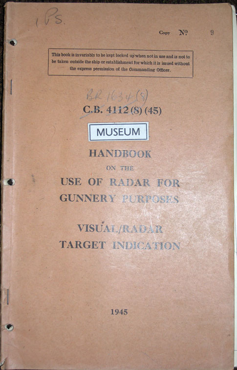

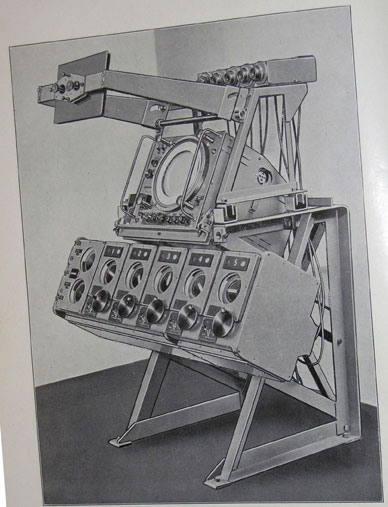
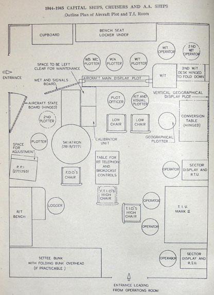
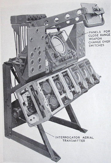
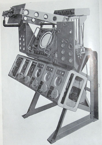
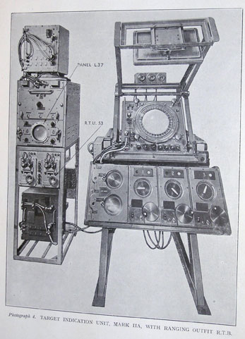
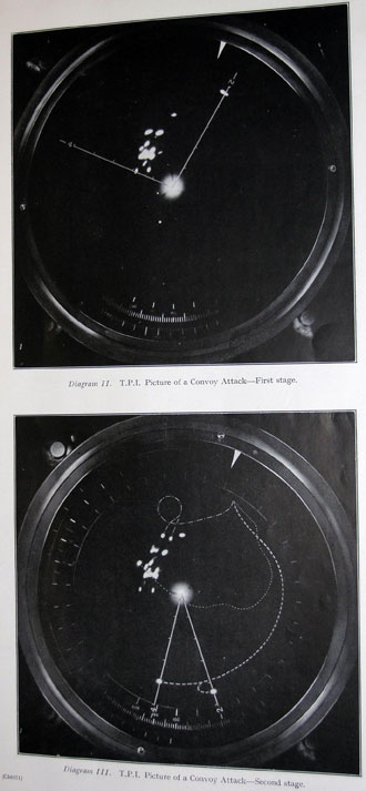
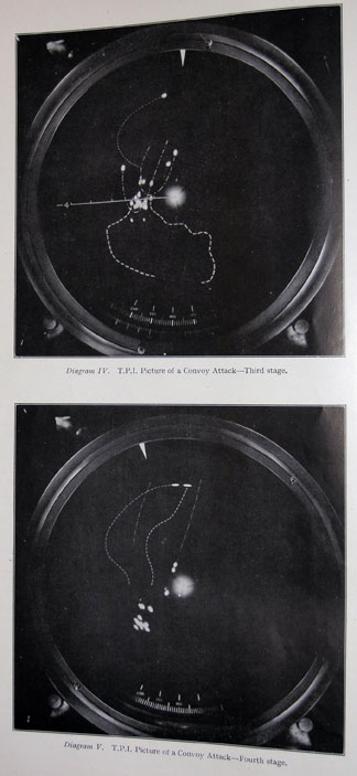
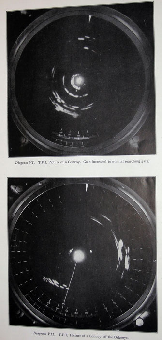
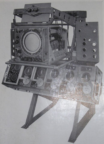

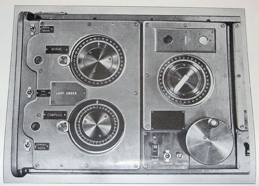
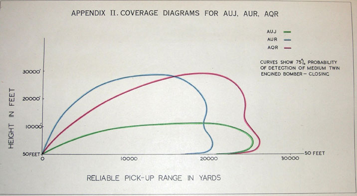