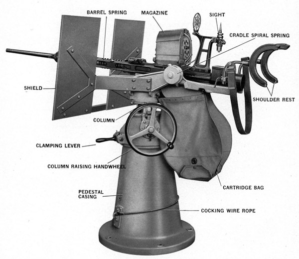
Figure 1-Exterior view showing general arrangement of the Mark 2 and Mark 4,
20 mm. AA Gun and Mount
19
Chapter 2 MARK 2 MOD. 2 AND MARK 4 MOD. 2 GUN MOUNTS
DESCRIPTION
The mount, Figure 1, permits the height of the gun trunnion above the deck to be easily and rapidly altered for any sight angle, thus enabling the gunlayer to assume the easiest position. This is done by the column raising handwheel mounted on the pedestal head. A tubular column supports the trunnion bracket and carries an internal thread that mates with a screw, driven by the handwheel. The rotatable pedestal head may be locked in any position by the clamping lever. On the base of the pedestal is also located the bracket for the cocking wire rope.
The gun can be trained through 360 degrees and continued around by means of the rotatable combined trunnion bracket and pivot. There is no stop; therefore, the training can be continued on any target without stopping. Train is limited by the length of power cable when mounts are equipped with Mark 14 Mod. 2 gun sight.
The gun can be elevated from minus 5 degrees to plus 87 by means of the rotatable cradle.
The pedestal of the Mark 4 mount has two brackets for the cocking wire rope. The wire rope is hooked in the lower bracket for use when cocking the gun. When the gun has been cocked, the upper end of the cocking wire rope is unhooked from the breech bar, wrapped around the pedestal and hooked over the upper bracket. The lower bracket for the cocking wire rope is shown in Figure 1.
The Mark 2 Mod. 2 mount has the cocking wire rope attached to a spring controlled reel that winds up the cocking rope inside the pedestal when it is not in use.
20
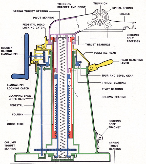
Figure 2-Diagrammatic Arrangement of Mount
Green-Fixed Pedestal
Red-Tubular column
Yellow-Pedestal head
Purple-Combined trunnion bracket and pivot
Blue-Column raising spindle and drive from handwheel
21
CONSTRUCTION
MOUNT CONSTRUCTION
NOTE-Figure 2 is diagrammatic and colored for the purpose of showing operation and is not accurate in construction details.
Plate 1 is a detailed section showing construction and OE and part numbers. There are five principal parts in the mount as follows:
Fixed Pedestal in green, Figure 2 and Plate 1, supports the mount and is bolted to the deck. A cocking wire rope bracket is bolted to the outside and is used to hook the wire rope on when cocking the gun. A bottom cover plate is bolted underneath the pedestal and is the main support for the equalizing springs, the column raising spindle, and the vertical shaft of the gear train. This bottom cover plate has a shim pack which provides the means of adjustment for free movement of the column. A guide tube is fixed within the pedestal and is provided with a vertical keyway in which slides the key on the tubular column.
Tubular Column in red, Figure 2 and Plate 1, is constructed with internal threads at its lower end. These internal threads engage external threads on the column raising spindle in blue on Figure 2. The handwheel operates the column raising spindle. The drive from the handwheel is shown in blue on Figure 2 and Plate I. The helical springs are inside the column raising spindle and the pivot and they are placed in series in compression, being separated by a spacing ring. Guide tubes hold these springs, the lower external guide tube being supported by a thrust bearing in a bushing on the bottom cover plate.
CAUTION-These compressed helical springs must not be disassembled unless a special fixture is used. The heavy compression these springs are under will cause serious injury unless the compression is eased off.
Pedestal Head in yellow, Figure 2 and Plate 1, through which the column rises, is able to rotate around the top of the fixed pedestal but can be held in any desired position by a spring steel clamping band that is operated by a lever. The pedestal head contains the handwheel drive, a double gear consisting of a bevel and spur for the purpose of transmitting the drive, and the clamping band with its lever.
Combined Trunnion Bracket and Pivot in purple, Figure 2 and Plate 1, is free to rotate around the top of the column on thrust bearings, which take upward and downward thrust, and in roller bearings located between the column and the trunnion bracket and pivot. It carries the trunnion arms that have plain bearings for the trunnion pins of the cradle.
NOTE-Two holes, each being one and one-half inches in diameter, are provided in the trunnion arms. These holes are directly above the center of gravity of the mount and a cable through these holes will support the mount in a vertical position.
CRADLE MARK 4 MOD. 2
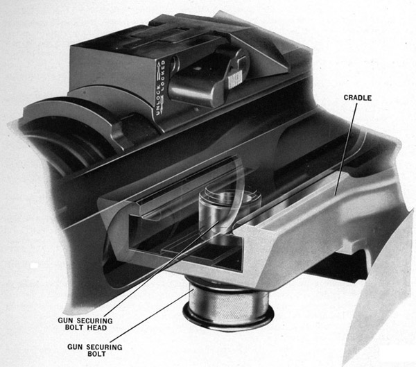
The cradle supports the gun and is carried on two trunnion pins located in the arms which extend rearward on the carriage. The cradle rotates freely on the right trunnion pin. The left trunnion pin is keyed to the cradle in order to form an abutment for the cradle spiral spring.
In some earlier cradles, two cavities or pockets were cast in the rear end and these were filled with lead. See Section C-C, Plate 1, Later cradles were cast solid. The cradle is provided with machined groves at the front and rear end in which the shoes of the gun breech casing engage. See Figure 3. The gun is held in position in these grooves by a securing bolt assembled to the underside of the cradle. See Figure 3, and Plate 1.
The torsion spring which is assembled to the left trunnion pin and anchored in the housing, Figure 2 and Section A-A, Plate 1, is used to compensate for the unbalance of the oscillating parts about the trunnion. This spring is placed under tension when the cradle is locked in the 87 degree elevation by turning its housing two or three notches when assembling the housing to its cover.
22
The cradle may be locked in either 5 degree or 87 degree elevation by a locking bolt built in the right side of the carriage.
A sheave, mounted on a pin in a slot in the left rear corner of the cradle, is used to facilitate cocking the gun with wire rope assembly (OE-2029).
The cartridge bag which accumulates the fired cartridge cases is attached to the cradle at its rear end.
NOTE-Earlier cradles Marks 2 and 4 used on Marks 2 and 4 Mounts did not have provisions for mounting Mark 14 Mod. 2 sight, interfered with installation or removal of the integral type shoulder rest Mark 5, and lacked provision for the cocking rope sheave. Ordalts Nos. 1186, 1269, and 1366 were issued to all ships and stations equipped with 20 mm. Antiaircraft guns. Performance of these Ordalts corrects these conditions and converts the Mark 2 cradle to Mark 2 Mod. 1 and Mark 4 cradle to Mark 4 Mod. 1 cradle.
TRUNNION BRACKET AND PIVOT LOCKING BOLT
This lock is built into the right side of the carriage to lock the cradle in the plus 5 degree or plus 87 degree positions. It consists of: Locking bolt (OE-2070), bolt knob (OE-2072), bolt knob pin (OE-2140), bolt spring (OE-2074), bolt bushing (OE-2071), two spring retaining pins (OE-2141), and bushing retaining pin (OE-2260). See Plan View, Plate 1.
The large end of the bolt operates in a horizontally drilled hole in the carriage. Locking the cradle in position is accomplished by releasing the bolt knob so that it rests flush with the bushing. When it is desired to train the gun without restriction, or change the elevation position, the knob should be pulled out and turned one-quarter turn.
GUN SECURING BOLT
This bolt is assembled in the floor of the cradle. It is of the spring loaded type and should always be engaged in the breech casing when the gun is in place. This assembly consists of: Bolt (OE-2188), bolt locating pin (OE-2262), bolt spring (OE-2189), bolt withdrawing head (OE-2190), and withdrawing head securing pin (OE-2261). See Main Section View, Plate 1, also Figure 3.
To operate the bolt pull it downward by the withdrawing head located on the bottom of the cradle and turn one-quarter turn to hold it out of engagement.
CARTRIDGE BAG
This bag which collects the fired cartridges is suspended at its front end from the carriage and at its rear end from the cradle. A flap with a snap fastener is provided at the bottom of the bag to permit the bag to be emptied easily.
A weight suspended from the pivot bolt, which passes through extensions on the front end of the cheek plates, serves as a deflector for the cartridges when entering the bag. See Plate 1.
ROTATING THE PEDESTAL HEAD
The pedestal head can be turned by hand to any position desired when the clamping lever (Figure
1 and Plate 1) is raised. The pedestal head can be locked in any position by depressing the clamping lever.
NOTE-The column raising handwheel tends to turn idly during the rotation of the pedestal head, and the rotation of the head can be assisted by turning the handwheel.
RAISING OR LOWERING THE COLUMN
When the pedestal head is locked so that it cannot rotate the action of turning the handwheel, Figure 2 and Plate 1, drives the gear train (shown in blue). The column (shown in red) has threads that are engaged in the threads of the column raising spindle and is prevented from turning by a key that is in a vertical keyway in the guide tube. The column, therefore, rises with the gun and the weight of the rising parts is taken by the compressed internal helical springs which aid in raising the gun. The rise of the gun is limited by the upper stop ring secured to the top of the spindle. A lug on the spindle spur gear acts as the lower stop.
23
OPERATION
NOTE-A locking catch is provided to lock the handwheel and thus fix the column at any height. A housing catch is also fitted to lock the combined trunnion bracket and pivot, when it is in its lowest position, to the pedestal.
Figure 3-Gun Mounting showing securing shoes and securing bolt
24
MOUNT MARK 4 MOD. 3
GENERAL DESCRIPTION
This is a modification of the Mark 4 Mod. 2 mount to provide improved lubrication and exclude water from the interior of the mount.
In addition to the new lubrication provisions, this new mount uses Mark 4 Mod. 1 trunnion bracket and pivot, Mark 5 cradle, the cradle lock used on Mark 6 mounts, a modified pedestal casing, and a new pedestal head cover.
Due to the importance of incorporating additional lubrication provisions in Mark 2 and Mark 4 mounts now in service, Ordalt No. 1398, has been issued to cover such modifications as can be made on ship-board and at shore bases.
Detailed information regarding new lubrication provisions and parts used is given in the following paragraphs.
DETAILED DESCRIPTION
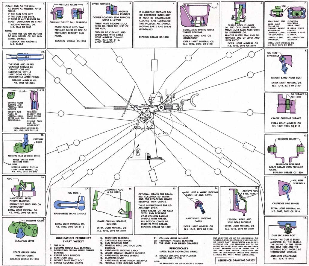
Lubrication : See lubrication chart, Figure 4.
(a) Direct lubrication is provided to the equalizing spring upper thrust bearing through a diagonally drilled hole leading from the top surface of the trunnion bracket and pivot to the bearing seat. A slotted pipe plug is used to close the hole. See Plate 1.
(b) Lubrication to the trunnion bracket and pivot upper and lower needle bearings is provided through an oil hole drilled in the top surface of the trunnion bracket and pivot. This hole is also closed by a slotted pipe plug. See Plate 1.
(c) Lubrication is provided to the bevel and spur wheel gear bushing through a hole in the pedestal head and drilled holes in the bevel and spur wheel gear. Lubrication to the pedestal head lower bearing is provided by squirting oil into the recess at the top of the pedestal through this plug hole. The hole in the pedestal head is fitted with a slotted pipe plug. See Plate 1.
(d) The upper part of the pedestal head lower bearing is lubricated by squirting oil into the trough located inside the head below the pipe plug hole referred to in (c). See Plate 1.
(e) Two oil holes are provided in the pedestal cover to lubricate the pedestal head bushing and column guide bushing. The holes are closed by slotted pipe plugs. See Plate 1.
(f) Lubrication is provided to the handwheel bevel pinion bearings through an oil hole drilled in the handwheel drive housing. This hole is closed by a slotted pipe plug. See Plate 1.
(g) Two pressure oilers are fitted 180 degrees apart in the wall of the trunnion bracket and pivot to provide lubrication to the two column thrust ball bearings.
(h) Pressure oilers are also screwed in the clamping lever spindle bearings to provide lubrication to the spindle. See Plate 1.
(i) A pressure fitting is also used in one end of the locking catch pivot pin to lubricate the pin. See Plate 1.
(j) A pipe plug in the pedestal casing permits access to a 45 degree street ell in the column guide bushing to provide lubrication to the column guide lower bearing bushing. See Plate 1.
(k) To permit access to the vertical shaft lower spur wheel and column raising spindle spur wheel for cleaning and lubrication, the rectangular hole near the lower part of the pedestal casing has been increased in size and relocated approximately 195 degrees clockwise. See Plate 1.
(l) To more effectively seal the column against the entrance of water, a new seal is employed in place of the felt ring formerly used. See Plate 1.
(m) A drain pipe extending from the bottom cover to the pedestal base flange permits drainage of water which may accumulate in the sections of the cover housing, the vertical shaft lower bearing and column lower bearing. At its outer end this pipe is fitted into a bushing which screws into the
25
base flange. The opening in the bushing through which the pipe extends is fitted with a pipe plug which should be reinstalled after draining is completed. The bearings in the cover may be lubricated if necessary through this pipe. See Plate 1.
(n) A pipe plug screwed in the base flange opposite the drain tube pipe plug can be removed to drain any water which may accumulate inside the pedestal casing. See Plate 1.
TRUNNION BRACKET AND PIVOT MARK 4 MOD. 1
The new part is a modification of Mark 4 trunnion bracket and pivot. The arms that extend rearward are longer to permit moving the cradle further back and provide more efficient ejection of cartridge cases when firing at high angles. The oil reservoir in the top of the trunnion bracket has been removed. Two oil holes with slotted pipe plugs are provided in the top surface to provide lubrication to the equalizing spring upper thrust bearing and the trunnion bracket and pivot needle bearings.
CRADLE MARK 5
The cradle is the same as used on Mark 6 Mounts and permits the gun to be elevated 90 degrees instead of 87 degrees as was the limit with the former cradle.
The depression of the gun is limited to 5 degrees. In this position the forward end of the cradle rests on two bosses cast in the top surface of the carriage.
CRADLE LOCK
The cradle lock is the same as used on Mark 6 Mounts.
PEDESTAL CASING
The pedestal casing is modified to provide access to the vertical shaft lower spur gear and column raising spindle spur wheel as described in paragraph (q) under "Lubrication". This change involves the use of a larger cocking rope bracket base.
PEDESTAL HEAD COVER
In place of the separate pedestal oil reservoir and lid fitted with a felt ring formerly used, a new cover is now employed. Two oil passages which provide lubricant to the column upper bushings are drilled in the top surface. These holes are closed by slotted plugs. A large recess is provided in the center of the cover into which the new seal is pressed.
26
LUBRICATION
Figure 4-Lubrication Chart Mark 4 Mod. 3 Mount
27
LUBRICATION-See lubrication chart, Figure 4. (Also applies to all Mark 2 and Mark 4 mounts modified in accordance with Ordalt No. 1398.)
(a) When the gun is being mounted in the cradle, the inside of the securing bolt hole in the breech casing, and the securing bolt itself should be thoroughly coated with Anti-seize compound, Navy Specification 52-C-19 (Int.).
(b) Equalizing spring upper thrust bearing (OE-2097)-Remove slotted pipe plug (OE-3525) from top surface of trunnion bracket and pivot and oil the bearing generously with extra light mineral oil, Navy Symbol 1042, 2075 or 2110, using an oil can. (On some older mounts, remove the y8" pipe plug in screw plug (OE-2081) to lubricate the bearing.)
(c) Trunnion bracket and pivot needle bearings-upper (OE-2096) and lower (OE-2095)-Remove second slotted pipe plug (OE-3525) from top surface of trunnion bracket and pivot and oil the bearing generously with extra light mineral oil, Navy Symbol 1042, 2075 or 2110, using an oil can.
(d) Pedestal head bushing (OE-2055)-Remove slotted pipe plug (OE-3525) located near outer edge of pedestal cover and oil generously with extra light mineral oil, Navy Symbol 1042, 2075 or 2110, using an oil can. (On older mounts inject the oil into the oil reservoir after removing the plug and its gasket or slotted pipe plug (OE-3525) from oil reservoir lid (OE-2014).
(e) Column guide bushing (OE-2016)-Remove slotted pipe plug (OE-3525) located near center of pedestal cover and oil generously with extra light mineral oil, Navy Symbol 1042, 2075 or 2110, using an oil can. (On older mounts this bushing is lubricated through the same hole mentioned in (d).
(f) Handwheel bevel pinion bearings (OE-2142)-Remove pipe plug (299759-5) in handwheel drive housing and oil generously with extra light mineral oil, Navy Symbol 1042, 2075 or 2110, using an oil can.
(g) Pedestal head locking catch spring bolt (OE-2048)-Oil tip of bolt with a few drops of extra light mineral oil, Navy Symbol 1042, 2075 or 2110.
(h) Handwheel locking catch spring bolt (OE-2051)-Oil tip of bolt with a few drops of extra light mineral oil, Navy Symbol 1042, 2075 or 2110.
(i) Handwheel spindle (OE-2128)-Apply a few drops of extra light mineral oil, Navy Symbol 1042, 2075 or 2110, to spindle adjacent to handwheel.
(j) Bevel and spur wheel gear ball thrust bearing (OE-2054) and pedestal head (299744-2)-Remove headless pipe plug (12-Z-307-7) in pedestal head, adjacent to handwheel and with an oil can inject extra light mineral oil, Navy Symbol 1042, 2075 or 2110 into trough in gear. Rotate column slowly when doing this to fill the trough. Also inject oil into the trough on the inside of the pedestal head to lubricate the upper part of the pedestal head bearing.
(k) Column lower bearing bushing (OE-2033)-Remove headless pipe plug (12-Z-307-7) in pedestal casing just above cocking rope bracket and fill 45° street ell (12-Z-326-56), screwed into the side of column guide bushing (OE-2016), with extra light mineral oil, Navy Symbol 1042, 2075 or 2110, using an oil can. Rotate column when oiling this point. Reinstall the pipe plug.
(l) Cradle trunnion pins (OE-2160 and OE-2161)-Force grease (OS-1350) into the two pressure oilers (OE-2259) above the pins, using grease gun (OE-1637).
(m) Column thrust bearings (two) OE-2093-Force grease (OS-1350) into the two pressure oilers (OE-2259), located 180° apart, in the side of the trunnion and pivot bracket (367558-1), using grease gun (OE-1637).
(n) Pedestal head locking catch pivot pin (OE-20491 force grease (OS-1350) into pressure oiler in the end of the pivot pin, using grease gun (OE-1637).
(o) Clamping lever spindle (OE-2037)-Force grease (OS-1350) into the two pressure oilers (OE-2259) in the pedestal head adjacent to clamping lever (OE-2045), using grease gun (OE-1637).
28
(p) Draining water from bottom cover and lubricating bottom cover ball thrust bearing (OE-2077) and lower column raising spindle ball bearing (OE-2134)-Remove pipe plug (12-Z-313-5) in bushing in base flange and inject grease (OS-1350) into tube. Reinstall pipe plug.
(q) When necessary vertical shaft spur wheel-lower (OE-2111) and column raising spindle spur wheel (OE-2112) can be cleaned and lubricated by removing the four screws (OE-2157) and lock washers (OE-2270) attaching cocking rope bracket assembly (300016) to the pedestal. Clean the gears by swabbing with a brush dipped in kerosene. Lubricate with bearing grease (0S-13501 applied by brush (OE-1607).
(1) On older mounts this operation is not practical without stripping the mount due to the cocking rope bracket base being smaller and located on the opposite side.
29
STRIPPING
Operation Number
1. Remove the gun assembly by pulling outward on the gun securing bolt (OE-2190) and sliding the gun out of the cradle.
2. Remove the cocking rope (OE-2029) if it is on the pedestal.
3. Remove the cartridge bag (OE-2198), the cartridge cheek plates (OE-2175-Right and OE-2174-Left) and weight and strap assembly (OE-2207).
4. Remove the shield from the trunnion bracket pivot, as follows: Remove shield strap (OE-2226) from the shield by removing bolts (OE-2227) and nuts (OE-2229). Remove shield plate (OE-2219) by taking out bolts (OE-2228) and nuts (OE-2229). Remove shield brackets (OE-2220 and OE-2221) from the trunnion bracket pivot by taking out bolts (OE-2218), nuts (OE-2217) and lock washers (OE-2275).
5. Remove the elevation counterbalance spring on the cradle, as follows: Lock the cradle at 90 degrees elevation. (Mounts with Mark 4 Mod. 1 and Mod. 2 cradles are limited to 87 degrees elevation.) Remove pin (OE-2268) that secures spring housing retaining nut (OE-2163). Remove this nut (OE-2163), using open end wrench (OE-2904) Figure 5. Remove (OE-2164) spring housing together with spring (OE-2169) and spring securing bolt (OE-2168). Remove housing cover (OE-2165) by taking out the securing screws (OE-2256).
NOTE-The cover and housing have serrated edges and the housing was turned clockwise two or three serrations before the serrated edges were joined. This was done to give the spring an initial tensioning. Keep hands clear of the serrated edges to avoid injury. The spring housing (OE-2164) has its bushing (OE-2166) pressed in. The spring bolt (OE-2168) is screwed in and can be removed with its washer (OE-2278) using adjustable wrench (OE-1606). The outer end of the spring is hooked over (OE-2168) with the end of the spring projecting to the left when looking into the case. See Figure 23.
Drive out pin (OE-2269) securing cradle trunnion pin nut. Remove nut (OE-2162) using open end wrench (OE-2904) and trunnion pin spanner (OE-31571, see Figure 52. Drive trunnion pin (OE-2160) inward, off its key (OE-2191). Remove both pins (OE-2160 and OE-2161).
6. Remove the cradle sub-assembly and strip as follows: Drive pin (OE-2261) out of gun
securing bolt head (OE-2190) and remove head. Remove spring (OE-2189) and bolt assembly from the cradle. Remove pin (OE-2262) from gun securing bolt (OE-2188).
7. Remove the two cap screws and lockwashers securing cover plate (299946-5) and remove cover and gasket (299946-6). Secure the helical equalizing springs (OE-2001) by removing the pivot closing cap screw (299923-7), and the cap, using wrench (OE-2901) Figure 5, from the recess in the center of the pivot. Remove screw plug (OE-2081), using wrench (OE-2901), from pivot closing cap (OE-2078). Insert this plug in the top of the tension tube and tighten until the flange touches the bearing race.
NOTE-This plug (OE-2081) when screwed into the tension tube (OE-2082) holds the 650-pound load of the equalizing springs; therefore, this plug must NEVER be removed unless special fixture (367539) is used. See page 47 for instructions on the use of this special fixture.
8. Raise the pivot head approximately 4 inches and remove the column raising handwheel assembly complete in its housing by taking out its securing bolts and washers (OE-2253 and OE-2270). To remove handwheel (OE-2104), remove nut (OE-2125) and washer (OE-2274). Remove key (OE-2258). Remove two set screws (OW-2137) from drive housing (OE-2110) and withdraw the pinion (OE-2108), bearings (OE-2142), spacer (OE-2123) and retainer (OE-2136). Remove pin (OE-2140), plunger (OE-2051) and spring (OE-2053). Place the mount on its side on a suitable support.
30
Figure 5-Mount Tools
31
Operation Number
9. Remove the trunnion bracket and pivot coupling nut securing bolt (OE-2069), washer (OE-2277) and coupling nut (OE-2032), using spanner wrench (OE-2903), Figure 5. Remove the trunnion bracket and pivot through the roller bearings at the top of the pedestal.
10. Remove cradle locking bolt locking screw (OE-3517), spring (OE-3516), ball (OE-3511), water seal (OE-3519), pin (OE-3513), lever (OE-3512), spacers (OE-3518), and plunger (299943-5). See Plate 1.
(a) On older mounts, remove the cradle locking bolt bushing retaining pin (OE-2260) and locking bolt assembly (OE-2009).
11. On older mounts remove the four trunnion bracket cover screws (OE-2249) and cover (OE-2061).
12. Remove retainer ring set screw (299923-7) and bearing lower retaining ring (OE-2034) from the lower end of the trunnion bracket and pivot, using spanner (OE-2906), Figure 5. Remove inner race of lower needle bearing (OE-2095).
13. Remove from the trunnion bracket and pivot, retaining ring lockwire (OE-2073), set screw (OE-2092), retaining ring (OE-2036), and inner race of column upper needle bearing (OE-2096).
14. Remove the three round head screws (367557-8) from trunnion bracket and pivot (367558-1). Insert a small punch through the screw holes and drive out upper race of thrust bearing (OE-2093). (a) On older mounts remove three countersunk screws (OE-2248) instead of round head screws.
15. Remove slotted pipe plugs (OE-3525) from trunnion bracket and pivot (367558-1). Also remove two pressure oilers (OE-2259) from side of trunnion bracket and pivot.
(a) On older mounts, remove plug and gasket from trunnion bracket cover (OE-2061).
16. Remove the column thrust ball bearing race (OE-2093) and the ball cage assembly (OE-2093) from the upper side of the flange at the top of the column.
17. Remove the equalizing springs and tube assembly complete with ball bearings at each end. This assembly is removed from the top.
NOTE-Do not unscrew the plug at the top of this assembly or attempt to disassemble the equalizing springs unless a special fixture is used. The heavy compression these springs are under will cause serious injury unless the compression is eased off.
See Instructions and Illustrations on Pages 47 to 52 for stripping and reassembling the equalizing springs.
18. Remove pipe plug (12-Z-313-5) and drain tube bushing (367564-2) from the base flange of pedestal (299742-2).
Also remove pipe plug (12-Z-313-5) from the opposite side of the base flange.
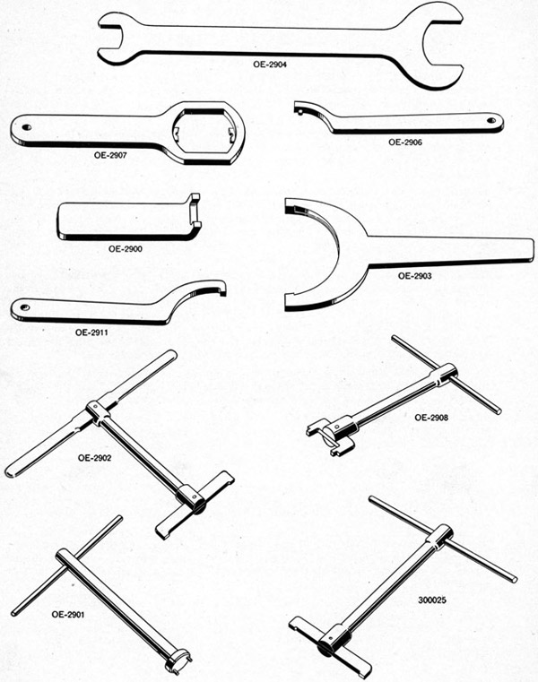
Mount Tools
OE-2900-Spanner for OE-2038 and OE-2039
OE-2901-Spanner for OE-2078 and OE-2081
OE-2902-Spanner for OE-2035
OE-2903--Spanner for OE-2032
OE-2904-Open end wrench for OE-2162 and OE-2163
OE-2906-Spanner for OE-2034
OE-2907-Spanner for OE-2129
OE-2908-Spanner for OE-2118
OE-2909-Tool for removing OE-2095
OE-2910-Tool for removing OE-2096
OE-2911-Spanner for OE-2126
OE-2912-Tool for assembling OE-2016, OE-2057 and OE-2055
OE-2913-Tool for assembling OE-2057 and OE-2055
OE-2914-Tool for assembling OE-2012, OE-2033 and removing OE-2016
OE-2915-Tool for removing OE-2016
OE-2916-Tool for removing OE-2114
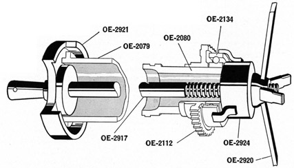
OE-2917-Spindle for assembling OE-2112, OE-2134, OE-2057, OE-2055, OE-2016 and OE-2033
OE-2918-Aligning tool for OE-2016
OE-2919-Tool for removing OE-2033
OE-2920-Handwheel for assembling OE-2134, OE-2112, OE-2057, OE-2055, OE-2016 and OE-2033
OE-2921-Disc for assembling OE-2033, OE-2016, OE-2112, and OE-2134
OE-2922-Puller for OE-2112 and OE-2134
OE-2923-Disc for removing OE-2112
OE-2924-Tool for assembling
OE-2112 and OE-2134 OE-2925-Puller for OE-2057 and OE-2055
OE-2926-Disc for removing OE-2057 and OE-2055
OE-2927-Puller for OE-2114
OE-2928-Puller for OE-2033
OE-3157-Spanner for OE-2161
300025-Spanner for OE-2116
367539-Helical equalizing spring compression tool
OE-1637-Grease gun, or 299832-5-Grease Gun
32
Operation Number
Remove the eight bottom cover screws (OE-2255) and lockwashers (OE-2273). To force cover (OE-2011) out of the pedestal, screw three of the cover screws into the tapped holes in the cover. Remove cover (OE-2011) with lower race and balls of thrust bearing (OE-2077), shims (OE-2294), (OE-2295), and (OE-2296). Remove the upper race of thrust bearing (OE-2077) from the lower end of column raising spindle (OE-2080). Remove the bearing race from cover (OE-2011).
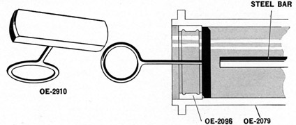
19. Remove the upper needle bearing retaining spring ring (OE-2075) from column. Remove the outer race and rollers of the trunnion bracket and pivot upper needle bearing (OE-2096) from the column (OE-2079), using tool (OE-2910), Figure 6. Tilt and insert tool (OE-2910) through the race and hold it against the lower side of the race by a pull on the loop handle of the tool. If sufficient force cannot be exerted to remove the race by pulling on the loop, it must be driven out by using a steel bar inserted from the lower side. Remove the lower bearing retaining spring ring.
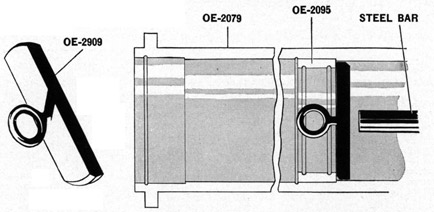
To remove the trunnion bracket and pivot lower needle bearing outer race (OE-2095) from the
Figure 6-Removing outer race (OE-2096)
from the column (OE-2079)
column (OE-2079) requires the use of tool (OE-2909), Figure 7. Insert tool (OE-2909) through the race and hold it against the lower side of race by a pull on the loop handle of the tool. If sufficient
Figure 7-Removing trunnion bracket and pivot lower needle
bearing outer race (OE-2095) from column (OE-2079)
force cannot be exerted to remove the race by pulling on the loop, the race must be driven out by using a steel bar inserted from the lower side.
33
Operation Number
20. Turn the column raising spindle assembly downward so that the lower end projects about six inches beyond the base of the pedestal so that the parts will be accessible.
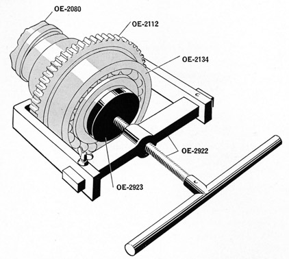
21. Remove the lower spring housing bushing lock screw (OE-2251), lower spring housing bushing (OE-2129) using spanner wrench (OE-2907) and retaining ring (OE-2126) using spanner wrench (OE-2911). Remove the bearing (OE-2134) and the spur gear (OE-2112) from the spindle (OE-2080), as follows : Place hooks of puller tool (OE-2922) back of the gear teeth. Place the tool disc (OE-2923) over the end of the column raising spindle (OE-2080) Figure 8. Turn the center screw of puller tool (OE-2922) inward so that it presses against the disc (OE-2923) as shown in Figure 8. Turning the tool handle will press the ball bearing (OE-2134) and spur wheel (OE-2112) off the column raising spindle (OE-2080). Remove column raising spindle keys (OE-2239).
Figure 8-Using puller (OE-2922) and disc (OE-2923) to strip ball
bearing and spur wheel from column raising spindle
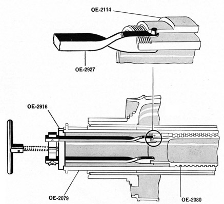
22. Withdraw the column raising spindle (OE-2080) complete with the upper roller bearing (OE-2056), the stop ring (OE-2114), keys (OE-2238), retainer ring (OE-2116) and lock screw (299923-7), through the top of the mount by rotating the spindle in the threads in the column (OE-2079).
23. Strip the column raising spindle assembly, as follows : Remove the column raising spindle needle bearing ring set screw (299923-7). Remove the column raising spindle needle bearing retaining ring (OE-2116) using tool (300025), Figure 5. Remove upper stop ring needle bearing (OE-2056). To remove column raising spindle upper stop ring (OE-2114) from upper end of column raising spindle (OE-2080) requires the insertion of the column raising spindle back into the column as shown in Figure 9, and the use of special tools as follows:
OE-2927-Puller
OE-2916-Bar
34
Figure 9-Removing column raising spindle upper stop ring (OE-2114) from column raising spindle (OE-2080)
Operation Number
Insert the pins that are on the lower ends of the puller (OE-2927) into the holes in the column raising spindle upper stop ring (OE-2114). Place the bar (OE-2916) on the upper end of column (OE-2079) and exert pressure by turning the center screw.
Column raising spindle (OE-2080) is stripped and can be unscrewed from pedestal.
24. Remove column lower bearing bushing retaining ring set screw (299923-7) and ring (OE-2035) using spanner wrench (OE-2902), Figure 5.
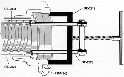
25. Remove the column lower bushing (OE-2033) and the bronze key (OE-2085) and screws (OE-2247) from the lower end of (OE-2079). Use puller (OE-2928) and tool (OE-2919) as shown in Figure 10. Hook the lugs that are on the lower ends of puller (OE-2928) into the holes in the column lower bearing bushing (OE-2033). Place special tool (OE-2919) on the lower end of the fixed pedestal casing (299742-2) and exert pressure with the center screw.
26. Remove the key (OE-2085) and screws (OE-2247) from the bushing (OE-2033).
27. Remove the six pedestal cover screws (12-Z-51-323) and lockwashers (12-Z-22-288) and loosen pedestal cover (367556-1) from the pedestal (299742-2).
(a) On older mounts remove the six oil reservoir lid screws (OE-2250) before loosening the lid (OE-2014) from oil reservoir (OE-2013).
28. Withdraw column (OE-2079) together with thrust bearing (OE-2093), coupling nut (OE-2032), bushing (OE-2031), pedestal head cover (367556-1), oil seal (367556-2), and key (OE-2090) from the top of the mount. To strip column (OE-2079), remove key (OE-2090) and slide the rest of the parts off the end of the column.
35
Operation Number
29. Oil seal (367556-2) should not be removed from pedestal head cover (367556-1) unless it is to be
replaced with a new one. It can be driven out with a drift applied from underneath.
(a) On older mounts remove lock wire (OE-2152), screw (OE-2015), and washers (OE-2017) from
oil reservoir (OE-2013) and remove the reservoir.
Figure 10-Removing column lower bearing bushing
(OE-2033) from column (OE-2079)
Figure 11-Removing bevel and spur wheel gear bushing (OE-2057) and pedestal head bushing (OE-2055) from fixed pedestal casing (299742-2)
30. Lift off the pedestal head assembly from the steel bushing at the upper end of the pedestal and strip as follows: Remove pedestal head locking catch pivot pin securing pin (OE-2241), pivot pin (OE-2049), pressure oiler (OE-2259), and catch (OE-2105).
36
Operation Number
31. Remove locking catch plunger plug pin (OE-2240), plug (OE-2047), spring (OE-2046), plunger securing pins (OE-2240), and plunger (OE-2048).
32. Mark the end of the clamping band lever screw on one edge with a prick punch, paint or crayon and place another mark on the pedestal head boss in line before removing the screw bushings. These parts can be reassembled in their original position and time will be saved in adjustment. Remove pins (OE-2242) from clamping band ends, unscrew bushings (OE-2038-Right Hand Thread, and OE-2039-Left Hand Thread) using angle wrench (OE-2900), Figure 5. Remove spindle (OE-2037), lever (OE-2086), clamping band assembly (OE-2040), and two pressure oilers (OE-2259).
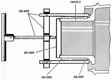
33. Remove the bevel and spur wheel gear (OE-2107), then remove the bevel and spur wheel gear bushing (OE-2057) and pedestal head bushing (OE-2055) from the upper end of the fixed pedestal casing (299742-2) by using special tools as follows:
OE-2925-Puller
OE-2926-Disc
Place puller (OE-2925) over the lower edge of bevel and spur wheel gear bushing (OE-2057). Place the disc (OE-2926) on the upper end of the fixed pedestal casing (299742-2). Apply pressure by turning the center screw as shown in Figure 11 and both bushings (OE-2057 and OE-2055) will be withdrawn.
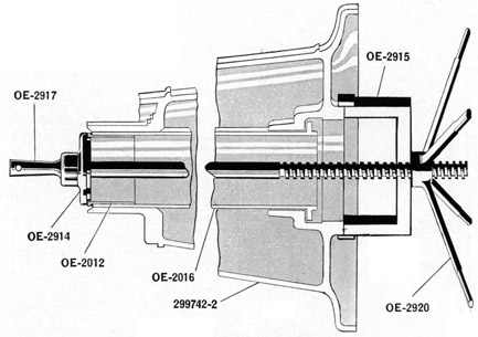
34. To remove column guide bushing (OE-2016) from fixed pedestal casing (299742-2) requires the following special tools:
OE-2914-Disc
OE-2915-Special Tool
OE-2920-Handwheel
OE-2917-Spindle
Remove the four cocking rope bracket base screws (OE-2257) and lockwashers (OE-2270) and take off base and bracket (300016). Reach through the opening in the pedestal and remove 45° street ell (12-Z-326-56) screwed into column guide bushing (OE-2016).
37
Operation Number
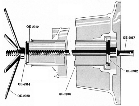
Place disc (OE-2914) against flange of bushing (OE-2012) at upper end of column guide bushing (OE-2016). Insert threaded bar (OE-2917) through the hole in the center and place tool (OE-2915) on the lower face of the fixed pedestal casing (299742-2) and over the threaded bar (OE-2917). Screw the handwheel tool (OE-2920) on the threaded bar and continue turning the handwheel until the column guide bushing (OE-2016) is free. See Figure 12.
39. Remove bevel and spur gear ball thrust bearing (OE-2054) from fixed pedestal.
40. Remove vertical shaft needle bearing outer race and rollers of (OE-2099) from fixed pedestal at upper end of vertical shaft.
41. Remove vertical shaft ball bearing housing bushing bolt (OE-2257), lockwasher (OE-2270) and remove the housing bushing assembly from over the gear hub and out of the fixed pedestal.
42. Remove the vertical shaft spur wheel, lower (OE-2111) from inside the fixed pedestal.
43. Remove vertical shaft ball bearing retaining ring set screw (299923-7) and retaining ring (OE-2118) using wrench (OE-2908), Figure 5.
45. Remove pipe plug (12-Z-307-7) in pedestal casing just above cocking rope bracket base hole.
38
REASSEMBLY
Operation Number
The pedestal is to be lying on its side in a suitable support.
1. Assemble the vertical shaft ball bearing (OE-2098) into its housing bushing (OE-2117) with retainer ring (OE-2118) using wrench (OE-2908) Figure 5. Coat bearing with grease (OS-1350). Install headless set screw (299923-7).
2. Place vertical shaft spur wheel, lower (OE-2111), inside the fixed pedestal at the vertical shaft lower hole with the hub down. Coat the teeth with grease (OS-1350).
3. Assemble the sub-assembly made in Operation 1 over the gear hub and into the fixed pedestal and secure with screws (OE-2257) and lockwashers (OE-2270).
4. Insert outer race and rollers of vertical shaft needle bearing (OE-2099) at upper end of vertical shaft. Lubricate with extra light mineral oil, N. S. 1042, 2075 or 2110.
5. Assemble bevel and spur gear thrust bearing (299766-5) on fixed pedestal. This bearing is optional with ball thrust bearing (OE-2054).
6. Assemble vertical shaft as follows:
(a) Assemble inner race of vertical shaft needle bearing (OE-2099) to vertical shaft upper spur wheel (OE-2109).
(b) Assemble vertical shaft upper bearing distance piece (OE-2121), gear and bearing race assembled in (a), spur wheel retainer nut washer upper (OE-2234), securing nut (OE-2120) and cotter (OE-2232) to vertical shaft (OE-2115).
NOTE-The parts assembled in a, b, are then assembled through the roller bearing at the top and into the gear (OE-2111) at the bottom. Coat teeth of spur wheel (OE-2109) with grease (OS-1350).
(c) Assemble spur wheel lower securing nut washer (OE-2235), nut (OE-2119), and cotter pin (OE-2232) to the lower end of shaft.
7. To assemble column upper bearing bronze bushing (OE-2012) into the column guide bushing (OE-2016) requires special tools as follows:
OE-2912-Disc (Figure 13)
OE-2917-Spindle
OE-2914-Special Tool
OE-2920-Handwheel
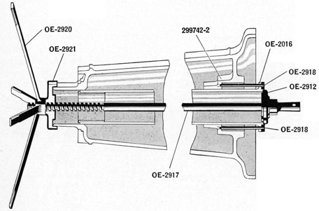
Place upper bearing bushing (OE-2012) into column guide bushing (OE-2016) so that the two internal vertical grooves (one on each side) are located 90 degrees from the 11 inch deep notch in the top of guide bushing (OE-2016). Lubricate with extra light mineral oil, N.S. 1042, 2075 or 2110.
Then place disc (OE-2912) on the lower end of guide bushing (OE-2016) and insert threaded bar (OE-2917) through the center of the disc. Place disc (OE-2914) on the flanged end of bushing (OE-2016) and over the threaded bar. Install and turn handwheel (OE-2920) until the bushing is seated. See Figure 13.
8. Insert the assembly made in Operation 7 into the fixed pedestal casing (299742-2) from the bottom. Lubricate with extra light mineral oil, N.S. 1042, 2075 or 2110. Some guide bushings (OE-2016) have two cutouts in the flange. On bushings with one cutout, insert the bushing as far as possible by hand, having the cutout toward the vertical shaft hole. On bushings with two cutouts, the cutout which is in line with the 1/4 pipe tap in the wall of the bushing must be toward the vertical shaft hole.
Place disc (OE-2912) on the flanged end of the column guide bushing (OE-2016). Insert the threaded bar of special tool (OE-2917) through the hole in the center of the disc (OE-2912). Insert the rods on special tool (OE-2918) through the holes in the flange of bushing (OE-2016) and into the tapped
40
Operation Number
holes in the fixed pedestal casing (299742-2). This is done to maintain alignment of the holes in the bushing (OE-2016) and fixed pedestal casing (299742-2). See Figure 14.
Place disc (OE-2921) over the end of the threaded bar (OE-2917) and on the upper end of the fixed pedestal casing (299742-2).
Screw the handwheel (OE-2920) on the threaded bar and continue turning the handwheel until the flange of column guide bushing (OE-2016) is tight against the fixed pedestal casing (299742-2).
Insert a rod through the hole in the handle of the threaded bar (OE-2917) to prevent its turning. Install the guide bushing securing bolts (OE-2254) and lockwashers (OE-2271).
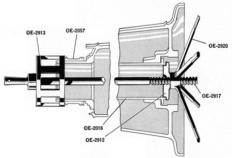
9. Assemble the bevel and spur wheel gear bushing (OE-2057) and pedestal head bushing (OE-2055) on the upper end of the fixed pedestal casing (299742-2). This requires special tools as follows:
OE-2913-Special Tool
OE-2920-Handwheel
OE-2912-Disc
OE-2917-Spindle
Place disc (OE-2912) against the lower face of column guide bushing (OE-2016) or against the lower face of fixed pedestal casing (299742-2). Insert the threaded bar (OE-2917) through the hole in the center of this disc (OE-2912). Line up bevel and spur wheel gear bushing (OE-2057) with fixed pedestal casing (299742-2) and place tool (OE-2913) against this bushing and on the threaded bar (OE-2917). Screw handwheel (OE-2920) on the threaded bar (OE-2917) and turn the hand-wheel until the bushing is tight against the fixed pedestal casing (299742-2). Remove handwheel (OE-2920) and tool (OE-2913) and repeat this process with pedestal head bushing (OE-2055). Insert a rod through the hole in the handle of threaded bar (OE-2917) to prevent its turning.
Figure 15-Installing bevel and spur wheel gear bushing (OE-2057) and
pedestal head bushing (OE-2055) on fixed pedestal casing (299742-2)
10. Assemble the bevel and spur gear wheel (OE-2107) on bushing (OE-2057). Coat the teeth with grease (OS-1350).
41
Operation Number
11. Assemble pedestal head as follows:
(a) Place clamping band assembly (OE-2040) in the pedestal head with ends projecting through the side between the clamping lever bosses. Assemble lever (OE-2045) and threaded spindle (OE-2037) with the mark on the end in line with the mark on the boss. These are the marks which were placed on these parts during the stripping operation. Assemble the threaded bushings (OE-2038 and OE-2039) on this spindle so that their inner ends enter the holes in the clamping band ends (OE-2041) and pin in place with (OE-2242). Use angle wrench (OE-2900).
NOTE-Threaded bushing (OE-2038) with the right-hand thread must be assembled on the right end of spindle (OE-2037) and bushing (OE-2039) with the left-hand thread must be placed on the left end of the spindle. As the lever is pressed down to tighten the band to hold the pedestal head in position, the bushings move inward on the threads. Moving the lever up to release the band causes the bushings to move outward.
(b) Screw the two oilers (OE-2259) into the clamping lever bearing bosses. Force grease (OS-1350) into the oilers, using grease gun (OE-1637).
(c) Assemble locking catch spring bolt (OE-2048), pedestal head lock plunger spring (OE-2046), plug (OE-2047), and two securing pins (OE-2240).
(d) Assemble locking catch (OE-2105), pivot pin (OE-2049) with tapped hole end facing counter-clockwise (viewed from above) and secure with one (OE-2241) pin. Assemble pressure oiler (OE-2259) in end of pivot pin.
(e) Assemble the pedestal head assembly on the steel bushing at the upper end of the pedestal. Lubricate inner surface of head and bushing with extra light mineral oil, N.S. 1042, 2075 or 2110.
12. If oil seal (367556-2) has been removed from pedestal head cover (367556-1) install a new one. Tap the new seal into place, being careful not to damage its case. The lip should point upward. Place cover assembly (367556-3) in position on top of the pedestal head with inner oil hole 180 degrees from the vertical shaft and secure with six screws (12-Z-51-323) and lock washers (12-Z-22-288).
(a) On older mounts assemble oil reservoir (OE-2013) (without oil tubes or wicks) to top of pedestal (299742-2) with 1/2 inch drilled hole 180 degrees from vertical shaft and secure with screws (OE-2015), washers (OE-2017), and lockwire (OE-2152).
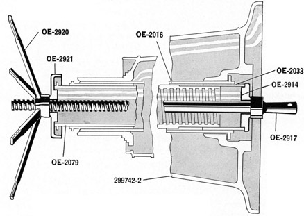
13. Assemble column lower bearing bushing (OE-2033) and guiding key (OE-2085) with screws (OE-2247). Insert this assembly into lower end of column guide bushing (OE-2016). Lubricate with extra light mineral oil, N.S. 1042, 2075 or 2110.
14. Assemble trunnion bracket and pivot coupling nut bushing (OE-2031) into coupling nut (OE-2032). 15. Assemble column thrust ball bearing (OE-2093) and parts assembled in 14, on the column (OE-2079). Pack bearings with grease (OS-1350).
NOTE-Inside diameters of thrust bearing rings are not alike. The smaller inside diameter ring should be placed adjacent to the column flange.
Assemble key (OE-2090) on column (OE-2079).
(a) On older mounts place oil reservoir cover (OE-2014) and packing (OE-2155) on column (OE-2079) before installing key (OE-2090).
NOTE-Insert this column assembly through the bronze bushing at the top of the pedestal and into the bronze bushing at the lower end of the pedestal, using the key-way in this bushing to line up the key in the 'column. Extreme care should be taken when moving the column through oil seal (367556-2) to prevent damaging the lip.
42
Operation Number
Should this lower bushing be forced out of the pedestal due to the possible tight fit on the column it may be tapped in, using a wood block to prevent damage to the bronze bushing. Be sure that the resistance is not caused by misalignment of the key and keyway.
If the resistance due to the fit of the bushing on the column cannot be overcome by tapping then the following tools must be used to press the bushing (OE-2033) in place as shown in Figure 16.
OE-2914-Disc (Figure 16)
OE-2921-Disc
OE-2917-Spindle
OE-2920-Handwheel
Place disc (OE-2914) on the lower end of column lower bearing bushing (OE-2033). Insert the threaded bar (OE-2917) through this disc. Place disc (OE-2921) on the upper end of the column (OE-2079) and over the threaded bar. Install and turn the handwheel (OE-2920) until the column lower bearing bushing (OE-2033) is against its seat. A bushing that is fully seated extends approximately 1 7/16 inches beyond the lower end of the column (OE-2079).
16. Assemble column lower bearing bushing retaining ring (OE-2035) on the column using spanner wrench (OE-2902) and install set screw (299923-7).
(a) On older mounts slide packing (OE-2155) into its seat in oil reservoir (OE-2013). Coat under-side of screws (OE-2250) with a plastic gasket paste such as (299998-3). If gasket paste is not available, white lead may be substituted. Assemble the screws in cover (OE-2014) but do not tighten.
17. Assemble column raising spindle as follows:
Assemble on upper end column raising spindle (OE-2080), two upper stop ring keys (OE-2238), stop ring (OE-2114), upper stop ring needle bearing (OE-2056) (hold rollers in place with an elastic band), retaining ring (OE-2116) using tool (300025) Figure 5, and set screw (299923-7).
18. Coat spindle (OE-2080) with grease (OS-1350) and install the assembly made in step 17 into the pedestal from the top and turn it through the threads in the column so that the lower end projects approximately six inches beyond the base of the pedestal. Remove the elastic band that has by now been forced off from the needle rollers.
19. Assemble the column raising spindle spur wheel (OE-2112) and the column raising spindle ball bearing (OE-2134) onto the column raising spindle (OE-2080). This requires special tools as follows:
OE-2921-Disc
OE-2917-Spindle
OE-2924-Special Tool
OF-2920- Handwheel
Place disc (OE-2921) on the upper end of column (OE-2079). Insert threaded bar (OE-2917) through this disc. Assemble the two column raising spindle spur wheel keys (OE-2239) on the spindle (OE-2080). Assemble the spur wheel (OE-2112) on the spindle (OE-2080) as far as possible by hand pressure. Place ball bearing (OE-2134) on spindle (OE-2080) against the hub of spur wheel (OE-2112). Place special tool (OE-2924) against the bearing, with the three lugs of the tool over the outside and onto the threaded bar. Install the handwheel (OE-2920) on the threaded bar and
Figure 17-Assembling column raising spindle spur wheel (OE-2112) and ball bearing (OE-2134) onto the column raising spindle (OE-2080)
turn down to a light pressure. Make certain that the disc (OE-2921) is piloted into the upper end of column (OE-2079) and that the ball bearing (OE-2134) is lined up with spindle (OE-2080). See Figure 17. Pack the bearing and coat the spur wheel with grease (OS-1350).
Tighten handwheel (OE-2920) and continue turning it until the inner end of the hub of spur wheel (OE-2112) is tight against the lower thread of spindle (OE-2080).
Install column raising spindle retaining ring (OE-2126) using special wrench (OE-2911), Figure 5.
Install lower spring housing bushing (OE-2129) using special wrench (OE-2907), Figure 5.
Install lower spring housing bushing lock screw (OE-2251).
Install the smaller ring and ball race of bottom cover ball thrust bearing (OE-2077). Pack the bearing with grease (OS-1350).
NOTE-Screw the column raising spindle into the pedestal until the side of the gear bears against the column guide bushing. Make certain that the teeth on the gear mesh with the teeth on the vertical shaft lower pillion when screwing the column raising spindle in. Pack grease (OS-1350) on the teeth of the gear and pinion.
44
Operation Number
20. Insert into column (OE-2079) the outer race and rollers of trunnion bracket and pivot lower needle bearing (OE-2095), snap ring (OE-2076), outer race and rollers of pivot upper needle bearing (OE-2096), and snap ring (OE-2075). Lubricate bearings with extra light mineral oil, N.S. 1042, 2075 or 2110.
21. Fill cover (OE-2011) with grease (OS-1350) and assemble it with the .0425 shim pack under the larger diameter ring of thrust ball bearing (OE-2077).
22. Install the bottom cover as assembled in step 21 to the pedestal, securing with lockwashers (OE-2273) and screws (OE-2255).
NOTE-Tighten up the screws gradually until the handwheel action is so tight that free movement is restricted. Measure the space between the bottom cover flange and the pedestal with a feeler gauge. Remove the cover and take out a pack of shims the thickness of which will be from .001 to .003 less than the thickness of the feeler gauge. Reassemble the cover assembly to the pedestal.
Insert drain tube (367564-1) into inner end of bushing (367564-2) and screw the bushing into the base flange of pedestal (299742-2). Install plug (OE-2283) in bushing. Install plug (OE-2283) in base flange on opposite side.
Complete filling the cover by removing headless pipe plug (OE-2283) from bottom of cover, installing a pressure oiler and forcing in grease (OS-1350), using grease gun (OE-1637). Remove oiler and reinstall plug flush with surface.
23. Assemble the Equalizing Spring and Tube Assembly, complete with bearing (OE-2094) and snap ring (OE-2084) into the mount from the top with the locking plug (OE-2081) at the top. Pack lower thrust bearing (OE-2094) with grease (OS-1350) before inserting assembly.
Place the mount in an upright position.
24. Assemble handwheel drive assembly (OE-2101) as follows:
To the handwheel drive housing (OE-2110) assemble oiler (OE-2138), locking catch plunger spring (OE-2053), plunger (OE-2051) and retaining pin (OE-2140). Assemble handwheel locking catch (OE-2050), locking catch pivot pin (OE-2245) and retaining screw (OE-2246). Assemble the outer ball bearing (OE-2142) and the bearing retainer (OE-2136) and the retainer adjusting screws (OE-2137) into the housing (OE-2110). Assemble the inner ball bearing (OE-2142) and bearing spacer (OE-2123) on pinion (OE-2108) and insert this group into the housing and through the outer bearing. On the outer end of this pinion shaft assemble the handwheel key (OE-2258), the handwheel assembly (OE-2102), the handwheel nut (OE-2125) and washer (OE-2274).
25. Install handwheel drive assembly (OE-2101) on the pedestal head. Use sufficient (OE-2135) shims to obtain free operation and secure with screws (OE-2253) and washers (OE-2270).
Oil handwheel pinion ball bearings (OE-2142) generously with extra light mineral oil, N.S. 1042, 2075, or 2110 through oil hole in housing using an oil can.
26. Place the smaller inside diameter ring of column thrust ball bearing race, and the ball cage assembly, of OE-2093 on the upper side of the flange at the top of the column. To assemble the trunnion bracket and pivot sub-assembly proceed as follows:
27. Screw two oilers (OE-2259) into the side wall of trunnion bracket and pivot (367558-1). Screw oiler (OE-2259) into trunnion pin boss. Assemble the larger inside diameter bearing race (OE-2093), inner race of bearing (OE-2096), retaining ring (OE-2036) with set screw (OE-2092) and lockwire (OE-2073).
28. Assemble inner race of bearing (OE-2095) with retainer ring (OE-2034) using spanner wrench (OE-2906) Figure 5, and set screw (299923-7).
45
Operation Number
29. Coat threads and underside of screws with a plastic gasket paste such as (299998-3) to make them water tight. If gasket paste is not available, white lead may be substituted. Assemble the screws in holes of trunnion bracket (367558-1).
(a) On older mounts coat the underside of screws (OE-2248) with gasket paste (299998-3) or white lead to make them watertight and assemble in the trunnion bracket and pivot. Coat edges of recess in trunnion bracket and pivot with plastic gasket paste (299998-3) or white lead and assemble trunnion bracket cover (OE-2061).
30. Install in the trunnion plunger (299943-5), lever (OE-3512), spacers (OE-3518), pin (OE-3513), seal (OE-3519), ball (OE-3511), spring (OE-3516), and screw (OE-3517). See Plate 1.
(a) On older mounts, assemble the cradle locking bolt assembly (OE-2009) as follows: On the bolt (OE-2070) assemble spring (OE-2074), bushing (OE-2071), pins (OE-2141), knob (OE-2072) and knob pin (OE-2140). Insert this assembly into the trunnion bracket and pivot and secure with pin (OE-2260).
31. Insert combined trunnion and pivot bracket assembly through the roller bearings at the top of the pedestal. Screw up the coupling nut (OE-2032) using spanner wrench (OE-2903) Figure 5 and lock with screw (OE-2069) and washer (OE-2277).
32. Release equalizing springs by removing plug (OE-2078), using wrench (OE-2901), Figure 5. Coat threads of plug (OE-2081) with plastic gasket paste or white lead and screw it into closing cap (OE-2078), using wrench (OE-2901). Coat threads of closing cap with plastic gasket paste or white lead and screw the assembly into the recess in trunnion bracket and pivot (367558-1), using wrench (OE-2901). Coat threads of lock screw (299923-7) with plastic gasket paste or white lead and screw it into hole in edge of closing cap to lock it in place.
Coat both sides of trunnion bracket cover gasket (299946-6) with plastic gasket paste or white lead, install cover (299946-5) and secure with lock washers (12-Z-22-252) and screws (299771-2).
33. Screw oiler (OE-2259) into trunnion pin boss on cradle (OE-2158). Assemble cheek plates (OE-2174-5) to the cradle, using screws (OE-2263). Assemble pin (OE-2262) in the gun securing bolt (OE-2188). Assemble the bolt and pin with the spring (OE-2189) in the cradle. Place withdrawing head (OE-2190) on the bolt, secure with pin (OE-2261).
34. Place cradle sub-assembly on pedestal with gun securing bolt, or front end, toward pedestal.
35. Fit key (OE-2191) in the long trunnion pin (OE-2160) and assemble in left hand trunnion boss with the head toward the center, assemble the short trunnion pin in right boss with pin head toward center. Assemble nut (OE-2162), using open end wrench (OE-2904) and spanner OE-3157. Insert pin (OE-2269).
36. Lock cradle in 90 degree elevation. (a) On older mounts cradle elevation is limited to 87 degrees.
37. Assemble spring housing cover (OE-2165) to trunnion bracket with screws (OE-2256). Assemble spring housing (OE-2164) and bearing (OE-2166). Screw on bolt (OE-2168) and washer (OE-2278), using adjustable wrench (OE-1606). Place spring (OE-2169) inside the spring housing with the outer end of the spring hooked over the screw stud, the spring winding clockwise from the stud looking into the cover. See Figure 23.
38. Place the assembly made in step 37 on the long trunnion pin with the inner end of the spring in the slot in the pin. Keep the serrated edges of the cover and case apart and turn the case to the right or clockwise two or three notches and engage the serrated edges. Assemble nut (OE-2163), using open end wrench (OE-2904) Figure 5, and pin (OE-2268). When turning the spring case keep hands away from the serrations to prevent injury.
NOTE-In order to improve the balance of the "gun when installing the Mark 14 Mod. 2 sight on the rear end of the cradle, or when interchanging solid and ribbed gun barrels,
46
Operation Number
the cradle spiral spring housing may be adjusted one or two notches from the standard setting. Cradle spiral spring spanner (367543-1), Figure 52, will be found helpful when making this adjustment.
39. Assemble the cartridge deflecting band assembly (OE-2207) to the front end of the cheek plates with bolt (OE-2177), nut (OE-2178), and cotter pin (OE-2230).
40. Assemble the cartridge bag assembly (OE-2198) with the inside leather reinforcement toward pedestal. Use bolts (OE-2172), nut (OE-2173), and cotter pins (OE-2231).
41. Lubricate mount thoroughly in accordance with lubrication instructions on Page 27.
42. Install all oil hole plugs and tighten securely.
43. Assemble the armor plate brackets (OE-2220 and OE-2221) to the trunnion bracket pivot with lockwashers (OE-2275), nuts (OE-2217), bolts (OE-2218). Assemble the plates (OE-2219) to the brackets with bolts (OE-2228), nuts (OE-2229), and assemble the cross strap (OE-2226) to the plates with bolts (OE-2227) and nuts (OE-2229).
47
EQUALIZING SPRING STRIPPING
The equalizing spring and tube assembly (OE-2001) must NOT be stripped unless the compressing tool assembly is used.
The following instructions cover the stripping and reassembly instructions using the modified tool assembly (367539) which will be available shortly. If only the original type tool (OE-2931) is available, then follow the same instructions, except omit Operation Number 1 which is not necessary.
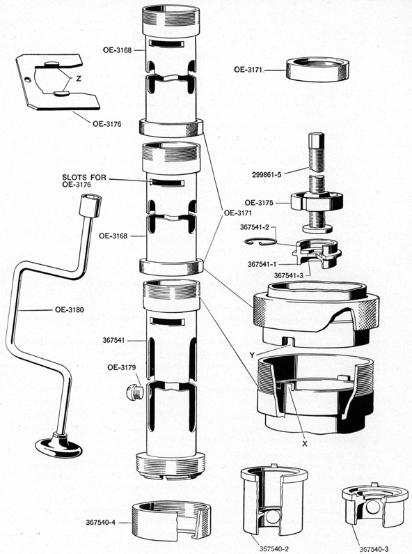
Equalizing spring compressing tool assembly (367539), Figure 18, consists of the following:
367541
-Equalizing spring compressing tool tube assembly-long
OE-3168
-Equalizing spring compressing tool tube assembly-short-2 required
OE-3180
-Equalizing spring tool wrench brace assembly
299861-5
-Equalizing spring tool screw assembly
OE-3171
-Equalizing spring compressing tool nut
OE-3176
-Equalizing spring stop plate assembly
OE-3179
-Equalizing spring tension tube plug
367540-4
-Equalizing spring compressing tool nut
367540-3
-Adapter-upper end-Mark 4 Mount
367540-2
-Adapter-upper end-Mark 6 Mount
367541-1
-Adapter-lower end
367541-2
-Snap ring for adapter
367541-3
-Thrust washer for adapter
NOTE-This tool is available on all tenders, repair ships, and at Navy Yards.
Operation Number
1. Place adapter (367540-3) on upper end of long tube assembly (367541), being sure to engage lugs on adapter in slots in end of tube. Slide nut (367540-4) over adapter and screw onto threaded end of tube.
2. Place a piece of round bar, approximately 3/4" in diameter, in a vise. Place the holes in the adapter on the end of the long tube over the bar to prevent tube from turning. Rest the threaded end of the tube on a suitable support.
3. Remove lower thrust bearing snap ring (OE-2084) and place the equalizing spring and tube assembly (OE-2001) in the long tube, with screw plug (OE-2081) entering first.
4. Install the tool screw assembly (299861-5) in the end of the long tube being careful to have keyways in nut (OE-3175), Figure 18, fitted over the lugs in the long tube. This nut must seat firmly over the lugs. Lubricate thrust bearing at the end of the screw with extra light mineral oil, Navy Symbol 1042, 2075 or 2110.
5. Slide compressing tool nut (OE-3171) over end of tool screw and thread it onto the long tube.
NOTE-This nut has to hold the entire load of the equalizing springs and must be turned down all the way on the threads of the long tube.
6. Install tool wrench brace assembly (OE-3180) on the end of the tool screw and turn it until adapter (367541-1) on the end of the screw contacts lower thrust bearing (OE-2094) which is on the end of the spring and tube assembly. Turn the wrench brace clockwise a few more turns, just enough to compress the equalizing springs so that their load is taken off screw plug (OE-2081).
7. Lift the long tube off the bar. Hold the equalizing spring and tube assembly against turning by having a helper hold it while removing plug (OE-2081) with spanner (OE-2901) inserted through the end of the tube. Place the tube back on the round bar that is in the vise.
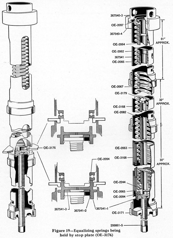
8. Turn the wrench brace counter-clockwise to release the spring until it is just short of the transverse slots, Figure 19, in the long tube. Insert stop plate assembly (OE-3176) in the transverse slots in long tube (367541).
48
Figure 18-Equalizing Spring Compressing Tool-367539
49
Operation Number
NOTE-Lugs (Z), Figure 18, on the stop plate must be toward wrench end of tube. This is necessary to provide a positive lock.
9. Turn wrench brace counter-clockwise again until the spring pressure is resting on the stop plate just installed.
NOTE-It is necessary that the coils of the springs be free from binding or cocking during the stripping operation. Use a soft hammer and tap on the springs through the slots in the tube. Do this whenever there is any indication of binding.
10. Unscrew compressing tool nut (OE-3171) from the end of the long tube installed in Operation 5. Remove wrench brace (OE-3180) and tool screw assembly from the long tube.
11. Install one short tube assembly (OE-3168) on the long tube assembly being certain that the lugs (X) in the short tube engage in the slots (Y) in the long tube, see Figure 18. Complete seating of the lugs in their slots is necessary to prevent the tubes twisting during stripping of the springs.
12. Screw tube nut (OE-3171) onto the threaded end of the long tube to join the two tubes, making sure that the lugs remain engaged in their slots.
13. Install the tool screw assembly, as instructed in Operation 4. Install wrench brace (OE-3180) on the end of the tool screw.
14. Turn wrench brace clockwise enough to release the spring load on stop plate (OE-3176) and remove the plate.
15. Turn the wrench brace counter-clockwise to release the spring until the thrust bearing is just short of the transverse slots in the short tube installed in Operation 11. Insert stop plate (OE-3176) in transverse slots with lugs toward wrench brace. Turn brace counter-clockwise until spring load rests on stop plate.
16. Remove wrench brace (OE-3180), tool nut (OE-3171), and the tool screw.
17. Install the second short tube assembly (OE-3168), as instructed in Operation 11 and repeat Operations 12 through 16 inclusive.
NOTE-If there is any indication of the springs binding, tap them through the long slots in the tube, using a soft hammer.
18. The lower thrust bearing (OE-2094), outer tube assembly (OE-2002), equalizing spring outer guide tube assembly (OE-2006), equalizing spring inner guide tube assembly (OE-2007), the two equalizing springs (OE-2062), spacing ring (OE-2067), and upper thrust bearing (OE-2097) can now be withdrawn from the tool.
50
51
Operation Number
To reassemble equalizing spring and tube assembly (OE-2001) proceed as follows:
1. With the one long and two short tube assemblies and the adapter assembled as instructed in the "Stripping Operation", place the parts in the tool in the following manner:
(a) Insert inner guide tube assembly (OE-2007) into the tool.
(b) Insert spring upper thrust bearing assembly (OE-2094) through the slots in long tube (367541) and place it on the inner guide tube housing bushing (OE-2068) and against the inner face of
adapter (3.67540-3).
(c) Insert one of the equalizing springs (OE-2062).
(e) Insert the remaining equalizing spring.
(f) Remove the spherical head guide plug (OE-3179) which is stowed in the side of long tube (367541) and screw the plug into the end of tension tube (OE-2082), which is a part of outer and inner tube assembly (OE-2002), to guide the tension tube into inner guide tube assembly (OE-2007).
(g) If outer and inner tube assembly (OE-2002) was stripped after being removed from the tool, reassemble it by placing tension tube (OE-2082) through bushing (OE-2065) in equalizing spring outer guide tube assembly (OE-2006). Install retaining pin (OE-2244) in bushing and tube. Install this assembly in the tool.
(h) Assemble spring lower thrust bearing (OE-2094) on the lower end of guide tube assembly (OE-2006) with race having the smaller inside diameter adjacent to the flange.
NOTE-Do not assemble snap ring (OE-2084) in the tube bushing until the compression of the springs is completed and the assembly is removed from the compressing tool.
2. Install tool screw assembly (299861-5) in the end of the tool. Be careful to have the keyways on screw nut (OE-3175) fitted over the lugs in the tube. This nut must fit firmly over the lugs.
3. Slide tool nut (OE-3171) over the end of the screw and thread it onto the tube.
NOTE-This nut has to hold the entire pressure of the equalizing springs and therefore, must be turned down all the way on the threads of the tube.
4. Install and turn wrench brace (OE-3180) clockwise so as to put a slight tension on the equalizing springs.
CAUTION-See that the spacing ring (OE-2067) is in place between the equalizing springs. Make certain that the springs are in alignment, see Figure 19. Keep watch of the end of the inner guide tube (OE-2064) when it gets into a position where it will contact the spacing ring (OE-2067); also see that when the second section of the equalizing spring contacts the end of the inner guide tube (OE-2064) all parts (spacing ring and springs) are properly aligned.
5. Turn the wrench brace clockwise to compress the springs until the thrust bearing is just beyond the transverse slots, see Figure 19, in the second short tube. Insert stop plate (OE-3176) in these transverse slots as shown.
NOTE-The lugs on the stop plate must be toward the wrench brace end of the tube. This is necessary to provide a positive lock.
6. Turn the wrench brace counter-clockwise until the spring pressure is resting on stop plate (OE-3176) in the second short tube thereby leaving the first short tube free of the springs so it can be removed.
52
Operation Number
NOTE-It is necessary that the coils of the springs be free of binding or cocking during the entire reassembly operation. Use a soft hammer and tap on the springs through the slots in the tubes. Do this whenever there is any indication of binding. When the end of tension tube (OE-2082) meets the end of the inner guide tube (OE-2064) (during the compressing of the springs), the end of tension tube (OE-2082) will be guided into the end of inner tube (OE-2064) by the spherical head plug (OE-3179). Be careful the ends of these tubes do not meet and cause damage.
7. Remove wrench brace (OE-3180), tool tube nut (OE-3171), and tool screw. Remove the short tube that was freed of the springs in Operation 6.
8. Reinstall tool screw tool nut (OE-3171), and wrench brace (OE-3180) on the short tube and turn the wrench brace clockwise to relieve the pressure of the springs on stop plate (OE-3176). Remove the plate. Turn the wrench brace clockwise until the springs have been compressed so that the thrust bearing is just beyond the transverse slots in the long tube. Insert stop plate in the transverse slots.
9. Repeat procedure described in Operation 6.
10. Repeat procedure described in Operation 7, which will place the entire equalizing spring and tube assembly in the long tube resting against stop plate (OE-3176). Reinstall the tool screw, tool nut, and wrench brace. Turn the brace clockwise to relieve the pressure of the springs on the stop plate. Remove the plate.
11. Continue turning the brace clockwise until the inner guide tube (OE-2064) projects through the upper thrust bearing at the vise end of the tool tube.
12. Lift the tool off the bar in the vise, remove spherical head plug (OE-3179), and assemble screw plug (OE-2081) in guide tube (OE-2082), using wrench (OE-2901).
NOTE-Hold the equalizing spring assembly when screwing the plug into the tube so as to be sure the plug is turned all the way in the tube. This plug takes all the thrust of the springs and it must be firmly seated or serious injury will result if it is only holding by a few threads.
53
STRIPPING
Operation Number
1. Remove the gun assembly by pulling outward on the gun securing bolt GM-188 and sliding the gun out of the cradle.
2. Remove the cocking wire rope GM-37 and its reel by removing the filler piece and cover. If other type of cocking device is used, remove it.
3. Remove the cartridge bag, GM-187 assembly, the cartridge cheek plates GM-175-Right and GM-174-Left and weight GM-170 assembly.
4. Remove the shield assembly from the trunnion bracket pivot. Stripping can be done as follows:
(a) Remove oil reservoir cover screws and empty reservoir and oil well at top of trunnion pivot.
(b) Remove shield SH-4 by taking out bolts SH-9, SH-10, and nuts SH-11.
(c) Remove shield brackets SH-2-R.H. and SH-2-L.H. from the trunnion bracket pivot by taking out bolts SH-6, nuts SH-7, and lockwashers SH-8.
5. Remove the elevation counterbalance spring on the cradle as follows:
(a) Lock the cradle at 85 degrees elevation.
(b) Remove pin GM-197 that secures spring housing retaining nut GM-163. Remove this nut GM-163, using box wrench (OE-2905).
(c) Remove the spring housing complete with spring GM-196 assembly. Remove housing cover GM-165 by taking out the securing screws GM-139.
NOTE-The cover and case have serrated edges and the case was turned clockwise two or three serrations before the serrated edges were joined. This was done to give the spring an initial tensioning. The spring housing GM-164 has its bushing GM-166 pressed in. The spring bolt GM-168 is screwed in and can be removed with its washer using box wrench (OE-2930) to remove the bolt. The outer end of the spring is hooked over GM-168 with the spring winding clockwise from the bolt, looking into the cover.
(d) Drive out pin GM-195 securing cradle trunnion pin nut. Remove nut GM-162 using box wrench (OE-2904).
(e) Drive trunnion pin GM-160 inward off its key GM-192. Remove both pins.
6. Remove the column raising handwheel assembly complete in its housing GM-221 by taking out the securing bolts GM-90 and washers GM-91 below the handwheel.
7. Place the mounting on its side on suitable chocks.
8. Remove trunnion bracket and pivot assembly as follows:
(a) Place column GM-109 in lowest position.
(b) Secure the helical springs (OE-2062) by removing the pivot closing cap GM-132, which is in the recess in the center of the pivot, taking out the screw plug GM-133 stowed therein, and inserting this plug in the top of the tension tube GM-134 (just below).
(c) Remove horizontal bolt GM-123 (in recess for housing catch on pivot) securing coupling nut.
(d) Raise the column sufficiently to remove the coupling nut GM-110 complete with bushing GM-131 below the upward thrust bearing, GM-154, and this bearing GM-154.
(e) Withdraw trunnion bracket and pivot assembly, the upward ring of the downward thrust bearing GM-154 coming with it, but leaving behind the outer rings GM-157-OR and rollers of the needle bearings GM-157.
(f) Remove outer ring with rollers GM-157-OR of the needle bearing GM-157.
9. Withdraw the thrust bearing GM-74 of the double gear GM-42.
10. Take out the vertical bolts GM-23 securing the column guide bushing GM-3 and withdraw the column guide bushing.
11. The stripping of the various sub-assemblies presents no particular difficulty except that should it be necessary to take the tension off the helical equalizing spring, special apparatus will be required. See Pages 47 through 52 for instructions and illustrations.
54
REASSEMBLY
Operation Number
1. Set the pedestal on its side on suitable chocks.
2. Assemble the vertical shaft drive gear as follows:
(a) Insert lower ball bearing housing sub-assembly GM-51 and secure with bolts GM-24 and washers GM-28.
(b) Insert outer ring and rollers GM-85-OR of the needle bearing at upper end of shaft.
(c) Install the thrust bearing GM-74 of the double gear GM-42.
(d) Insert vertical shaft sub-assembly GM-50, threading the shaft through the roller bearing at the upper end and through the spur wheel and ball bearing at the lower end.
(e) Put on washer and nut at lower end and secure with split pin.
3. Insert column guide bushing complete with bushing at upper end. Secure with vertical bolts GM-23 and washers at the lower end.
4. Install the double gear GM-42.
5. Install the pedestal head sub-assembly GM-41, including the handwheel locking catch GM-60, clamping band assembly G-66-AB and catch locking trunnion bracket.
6. Fix water excluding packing ring GM-30 for the oil reservoir at top of pedestal head, place reservoir GM-5 and secure with bolts GM-7, packing GM-31, and washers GM-8. Secure bolt heads with wire GM-29. Put on lid GM-6 and secure with screws GM-25 temporarily.
7. Insert column GM-109 first threading on the upward thrust ball bearing GM-154 at the top, and the coupling nut GM-110 complete with bushing GM-131. Insert lower bearing bushing GM-111 at lower end, entering the key GM-142 in the keyway in the column guide bushing GM-3. Put on the retaining ring GM-113 (at the lower end) and secure with vertical set screw GM-145. Take care that the upward thrust ball bearing GM-154 is placed the right way uppermost as the diameters of the upper and the lower rings differ.
8. Insert the column raising spindle sub-assembly GM-47 including the spur gear GM-42 secured by a set screw, ball bearing journal bearing GM-74, and retaining ring GM-63. Insert the upper stop ring GM-48 and needle bearing GM-76 at the upper end of the column raising spindle; put on the retaining ring GM-49 and secure by set screw GM-93.
NOTE-Assembly operations can be performed by turning the column raising spindle downward so that the lower end projects about six inches beyond the base of the pedestal.
9. Insert the helical equalizing springs sub-assembly (OE-2001) under compression, through the bottom of the spindle. Screw the housing for the lower thrust bearing GM-119 for this sub-assembly into the spindle, and secure with set screws.
10. Insert outer rings, complete with rollers of needle bearings GM-157 of the pivot, inside the column and place the securing rings GM-114.
11. Put on the bottom cover sub-assembly GM-2 including ball thrust bearing GM-83 for the column and secure with vertical bolts GM-22 and washers GM-26.
12. Place the pedestal in the vertical position. Place handwheel gear housing sub-assembly GM-221 and secure with bolts GM-90 and washers GM-91. Place lower ring and balls of downward thrust bearing GM-154 (on upper side of flange at top of column).
13. Insert combined trunnion bracket and pivot sub-assembly, including inner ring of upper needle bearing GM-157 secured by retaining ring GM-114 and set screw GM-144, and inner ring of lower needle bearing GM-156 secured by retaining ring GM-112 and set screw GM-145, and upper ring of upward thrust bearing GM-154, also cradle locking bolt GM-124. Screw up coupling nut GM-110 and secure with bolt GM-123.
55
Operation Number
14. Release equalizing helical springs by removing plug GM-133, and then stow the latter in the pivot closing cap GM-132. Insert pivot closing cap GM-132 and secure with set screw GM-145, making a water-tight joint.
15. Install cradle sub-assembly GM-159, including trunnion pins GM-161, GM-160, and trunnion pin nut GM-162, secured with pin GM-195. Lock the cradle in the 82 degree elevation position.
16. Install the elevation counter-balance spring assembly GM-169, the spring in housing GM-164, secured with bolt GM-168 and washer, entering the free end of the spring in the slot, on the trunnion pinion nut GM-162 and secure with pin GM-195.
17. Fit cartridge deflecting band GM-170 complete with weight GM-179 and secure with pivot bolt GM-177, nut GM-178, and split pin GM-200. Hang the cartridge bag by bolts GM-172 and nuts GM-173 and secure with split pins. Attach wire rope bracket for cocking gun.
18. Lubricate mount according to instructions on Page 27 and reinstall filler plugs and gaskets.
56
Plate 1
PLATE 1
General Arrangement of Mark 4 Mod. 3
20 MM Antiaircraft Gun Mount
Between page 56 and 57
(Large size image.)