Pouring is a critical operation in the production of a casting and one which should be carefully conducted. The ladle equipment should be designed for high structural strength and, in the case of geared ladles, for foolproof mechanical operation. Because of the high temperatures involved, a reasonable factor of safety should be used when lining a ladle or when deciding whether an old lining is fit for use.
To avoid accidents, frequent and careful inspection should be made of all parts of the metal-handling equipment (bowls, bails, trunnions, etc.) to detect badly scaled or cracked areas. Defective equipment causes bad castings. When geared ladles are used, any indication of trouble should be immediately checked by carefully examining all gears for excessive tooth wear or broken teeth. Any ladle in a doubtful condition should not be used.
TYPES OF LADLES
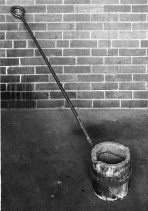
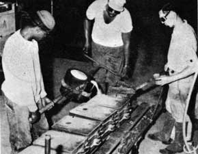
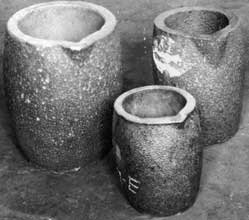
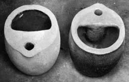
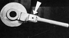
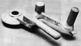
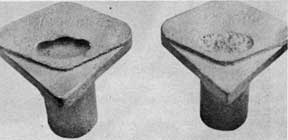
Ladles used aboard repair ships are of two basic types. The lip-pouring ladle is shown in figure 186 and the teapot, or bottom-pouring ladle, is shown in figure 187. Crucibles, such as shown in figure 188, are a type of lip-pouring ladle. Teapot crucibles are shown in figure 189.
Ladle bowls are usually of welded or pressed steel construction. Trunnions on the larger ladles are often attached by both riveting and welding for maximum safety.
LADLE LININGS
Ladle linings have an important bearing on the cleanliness of castings produced. If not sufficiently refractory, linings will melt and form slag, which is difficult to keep out of the casting. Because of the high temperature involved, this is most apt to occur in pouring steel. Slagging of the ladle lining is less with gray iron and bronze, and negligible with aluminum.
If the lining material has insufficient dry strength, it will crumble around the upper part of the ladle. The upper part of the lining is not in contact with the molten metal and does not develop strength by fusing or fluxing. When the ladle is tilted to a pouring position, parts of the crumbled rim will fall into the stream of metal entering the mold or into open risers.
A lining mixture which will have the desired properties can be obtained by thoroughly mixing the following materials in a sand muller.
Used steel backing sand (All-purpose backing sand - chapter IV)
81.5 percent
Silica flour
15.0 percent
Bentonite
2.0 percent
Dextrine
1.5 percent
Water
5.0 percent of the dry ingredients
A mixture of silica sand or ganister, fire-clay, and water can also be used when available. This mixture contains 85to 95 percent of silica sand or ganister; the rest is fireclay. The exact percentage of silica sand or ganister and fire-clay are determined by how workable a mix is desired. More clay gives a more workable and sticky mixture but increases the amount of shrinkage when the lining is dried. With all types of refractory mixes, only enough water should be added to make the mixture workable. An excess of water, although making the mixture easier to handle, causes more shrinkage and cracks in the lining when it is dried. For low shrinkage and fewer cracks, use small amounts of water and clay.
Before ramming a lining in the ladle, arrangements must be made for venting the lining during drying. This is done by drilling 3/16 inch or 1/4 inch holes through the sides and bottom of the ladle shell on 3 to 4-inch centers. If this is not done, drying will take too long. Numerous injuries to personnel have resulted from the use of improperly dried ladles. When moisture is pocketed under molten metal, a large volume of water vapor is rapidly formed and the metal is blown out of the ladle with explosive force. In addition to this, even slight traces of moisture in ladle linings will cause porosity and casting unsoundness. The most practical way to determine when a ladle is dry is to apply heat until steam flows from the vent holes, and then continue to apply heat until this flow stops completely.
With a properly vented ladle shell, the lining is then rammed in place. It is best to use a wood or metal core to form the inside of the ladle. The form can be made with taper and allowance for lining thickness. After the bottom of the ladle is rammed into place, the form is centered with wedges and the sides of the lining rammed. A harder and more dense lining can be made and the water kept to a minimum when
140
a form is used. Also, the job is a lot easier than trying to ram a lining against vertical walls. When ramming a lining in layers, be sure to roughen the top of each layer before ramming in the next layer. After the lining has been rammed, the form is rapped lightly to loosen it and then drawn from the ladle. To make drawing of the form easier, and to keep the form from absorbing water from the mix, it should be covered with a thin layer of grease or with aluminum foil. If aluminum foil is used, it is peeled from the lining after the core has been removed. Care should be exercised so that aluminum foil does not fold and cause a deep crack in the lining. The ramming of the lining must be very hard and uniform. If the lining shows a tendency to crack into layers when the form is withdrawn, each layer was not roughened enough before the next was rammed in. Such a ladle can be dangerous to use.
The thickness of the lining varies with the metal to be handled and with the size of the ladle. For example, a ladle for the pouring of steel requires a heavier lining than one for cast iron, bronze, or aluminum because steel, at the high temperatures required, attacks the lining material much more rapidly than any of the other metal s.
A lining for a ladle to hold and pour 75 pounds of steel will have a thickness of about 1 inch on the bottom and 1 inch on the sides at the bottom and will taper to about 3/4 inch at the top of the ladle. This thickness is also satisfactory for any of the other metals. For the lower-melting-point metals, the main consideration in determining the thickness of lining is proper insulation in order to prevent chilling of the molten metal and to avoid damage to the ladle shells as a result of overheating.
Drying of a new or patched lining is an operation that can cause a lot of trouble if it is not done properly. A new lining or patch should be heated gently at first to get rid of most of the water without blowing a hole in the lining or cracking it because of steam pressure. Aboard ship, this can best be done by first drying the ladle in a core oven and then completing the drying with a torch. The torch should be positioned, with respect to the ladle, so as to insure complete combustion of the gas and delivery of maximum heat to the lining. If a new lining is heated too fast at the start, the water travels back to the shell and makes that part of the lining weak and soggy. After the lining or patch is thoroughly dried slowly, the temperature can be safely increased to as high as obtainable. It is desirable to maintain a new lining at red heat for several hours before using it. If a slowly heated new lining cracks, the ramming mixture contained too much clay or water.
ANYONE WHO POURS METAL FROM A LADLE WITH A DAMP LINING OR DAMP PATCH CAN EXPECT TO FIND UNPLANNED HOLES IN HIS CASTING.
Pouring lips of ladles are a frequent source of trouble because they are often patched and then proper drying of the patch is overlooked. A wet patch on a pouring lip will put gas in the metal and cause blowholes in the castings.
Patching of a ladle is best done when the lining is cold. All adhering slag and metal must be removed in the area to be patched. If possible, undercut the old lining to help hold the patch. Brush loose dirt from the old lining and wet the lining thoroughly. Patch large holes with the same mixture used for lining. Patch small holes and cracks with a mixture of four parts clean sand and one part fireclay. DRY A PATCH THE SAME AS A NEW LINING.
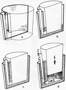
In figure 190 are shown the various steps in the lining of a teapot ladle. Part (a) is a cutaway view of the ladle shell. The bottom is rammed, the forms set in place, and refractory rammed on the side. Many times, a heavy-duty refractory brick is placed in the bottom of any ladle to take the force of the molten metal stream when the ladle is filled. This reduces erosion of the ladle bottom. Part (b) shows the sides partly rammed after the forms are set. The completed lining with forms still in place is shown in (c). Order of withdrawing the forms is shown in (d).
Ladles for steel are commonly used only once per lining because of the fluxing action of the metal at the high temperatures. In an emergency, if great care is used in skimming slag, ladles may be used twice for steel, but it is not good practice. This does not hold true for the other metals, however, and the ladles may be used for many heats. Care should be taken to remove all metal and slag after each use, but it is impossible to remove all of the debris. Therefore, ladles should be used for only one metal. A separate ladle should be used for each metal or the metal will become contaminated and unfit for use.
POURING THE MOLD
The placing of weights and clamps on a mold is only a minor operation in the making of a casting but one that will produce defects if not properly done. Weights are used to prevent the force of the molten metal from lifting the cope as it fills the mold, thereby producing a swelled casting or a runout. The position of the weight on the mold should be determined and the weight placed on the mold gently, without any movement of the weight across the top of the cope.
141
Any such movement can cause the cope to break or force sand into the gating system or open risers.
Clamps serve the same purpose as weights and are used to clamp the cope and drag together when the casting is poured in the flask. In placing the clamps, a wood wedge is usually used to tighten the clamp down on the flask. Before placing the clamp, the area next to the clamp should be cleaned of excess sand to prevent mold damage when the clamp is set. The wedge should be placed between the clamp and the top edge of the flask, the clamp brought up snug, and then tightened by driving the wedge. Care must be taken to hit the wedge and not the clamp or flask.
Although clamps and weights are used for the same purpose, clamps are much more dependable. It is too easy to underestimate the lifting power of the metal and to use too few weights. On the other hand, too many weights can crush a mold.
With the ladle thoroughly dried, preheated to a red heat, and securely in the bail, molten metal from the furnace is tapped into it. Filling the ladle to its brim is unwise from the standpoint of safety and for the production of good castings. Filling the ladle to its brim should be done only when absolutely necessary, and then extreme caution should be exercised in handling the ladle and pouring.
If the ladle is filled to about 3/4 of its capacity, metal will not flow over the lip until the ladle is inclined to an angle of approximately 60° from the horizontal. This permits a good control of the stream, making it possible to keep the ladle quite low and thus, keep the height of fall of the metal low. This lessens mold erosion, entrapment of air, formation of oxides, and metal spills.
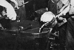
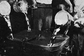
Figure 191 shows the proper method of pouring, while figure 192 shows poor pouring technique. In the good pouring technique, notice that the lip of the ladle is as close as possible to the mold.
Slag on the metal should be skimmed carefully prior to and during pouring. If a steel or iron slag is too fluid to be skimmed properly, dry silica sand should be spread across the surface of the molten metal to thicken the slag. Dry metal rods or special metal skimmers should be used for skimming or stirring metal. Wood skimmers or stirrers should never be used because the wood contains moisture which often produces unsoundness in castings.
SPEED OF POURING
The pouring basin should be filled quickly to prevent nonmetallics and slag from entering the mold cavity and must be kept full. In order to do this, the ladle stream must be controlled carefully. Once pouring has started, it must continue without interruption until the mold is filled. One allowable exception is to stop pouring through the sprue when the metal has filled 1/3 of a top riser. The riser is then filled last with hot metal to improve feeding. This exception applies only to top risers. With side risers, the mold might not be full when metal is seen in the riser.
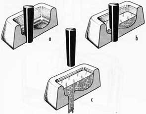
The use of a pouring basin and plug to get more uniform pouring is shown in figure 193. Part (a) shows the basin ready to receive the metal. In (b) the basin is partially filled. When the basin is properly filled, the plug is withdrawn as in (c). The use of a pouring basin permits better control of the metal entering the gating system. Another variation of this method is to put a thin sheet of the metal being poured over the sprue opening. It will melt out when the basin is filled with hot metal. Keep the basin full of metal at all times.
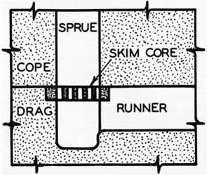
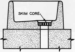
When pouring a metal that forms dross (especially aluminum, aluminum bronze, or magnesium), every effort must be made to avoid turbulent entry of the metal into the mold. It is particularly important in such cases that the lip of the ladle be as close to the pouring basin as possible. The sprue must be filled quickly and kept full so that the tendency for dross and entrapped air to enter the mold will be at a minimum. Here again the pouring basin and plug can be used to advantage. The use of skim gates or perforated cores placed in the sprue or pouring basin (as shown in figures 194 and 195) aids in removing dross from the metal and preventing its entrance into the casting cavity. Agitation of the molten metal while it is being transported to the mold also increases dross formation and gas absorption.
POURING TEMPERATURE
Close control of pouring temperatures is essential to the consistent production of good castings. An immersion pyrometer and an optical pyrometer are furnished for temperature determination. Because of the high temperature involved, the immersion pyrometer is not used for iron or steel. The Chromel-Alumel immersion thermocouples are limited to temperatures of 2,500°F. The optical instrument is impractical for nonferrous metals because their pouring temperatures are too low.
142
The operation of an immersion pyrometer is a simple matter. The instruments are usually of two types; a self-contained unit or the unit in which the immersion unit is connected by wires to the reading instrument. Before use, the pyrometer should be checked to make sure that the immersion part of the instrument is clean. Lead-wire pyrometers should be checked for any breaks or loose connections in the wire. When taking a reading, the immersion tip should be submerged in the molten metal to a depth of approximately 3 inches and moved slowly back and forth or in a circle. After the temperature reaches a fairly steady reading, it should be recorded. The immersion tip should then be withdrawn from the melt. Immersion pyrometers should be handled with care and periodic inspections made for proper upkeep. Whenever possible, the instruments should be checked and calibrated for good operation.
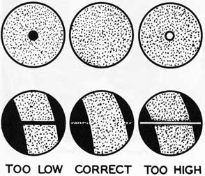
The optical pyrometer operates by matching the intensity of light from the molten metal with that of a standard light source within the instrument. Exact operating procedures are available with the instruments. Generally, the field of vision will be uniform, as shown in figure 196a, when the instrument is set at the proper temperature. If the instrument is set too high, the inner circle of the field will be brighter as in (b). If the inner circle is darker, the instrument is set at too low a reading. This instrument should be handled with care and given periodic checks and calibrations for proper operation.
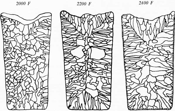
Excessive pouring temperatures (that is, temperatures above those required for the proper filling of the mold) result in excessive oxide or dross formation, segregation, rough and dirty casting surface, unnecessarily high liquid shrinkage, coarse-grain metal structure, and increased danger of cavities, tears and porosity. Figure 197 shows the increase in grain size that resulted with increased pouring temperatures for a copper-base alloy. Notice that the high pouring temperature resulted in a very coarse grain structure.
If the pouring temperatures are too low, entrapped gas and dross, misrun castings, or castings with surface laps (cold shuts) are likely
to result. Proper pouring temperatures for a given metal vary with the casting size, design, and desired rate of pouring. For this reason, the pouring ranges given below should be taken as a general guide only:
Metal
Pouring-Temperature Range
Steel
2850°F. to 2950°F.
Gray iron
2300°F. to 2600°F.
Aluminum
1250°F. to 1400°F.
Manganese bronze
1875°F. to 1975°F.
Compositions G & M
2000°F. to 2200°F.
In general, thin-walled castings are poured on the high side of the range and thick-walled castings on the low side.
SUMMARY
The important factors in pouring a casting are summarized as follows:
1. Ladle equipment must be kept in good repair.
2. All ladle linings must be rammed uniformly hard and be of the proper thickness.
3. All ladles must be thoroughly dried and at a red heat for some time before use with the high melting point alloys.
4. Ladles should not be filled to more than 3/4 of their capacity.
5. Metal should be skimmed free of all slag or dross before pouring.
6. In pouring, the ladle should be as close to the pouring cup or sprue as possible.
7. Once pouring has started, the stream should not be interrupted. A steady rate of pouring should be used and the sprue should be kept full at all times.
8. The metal should be poured at the correct temperature, neither too high nor too low.
143
Figure 186. Lip-pouring ladle.
Figure 187. Teapot ladle.
Figure 188. Lip-pouring crucibles.
Figure 189. Teapot crucibles.
Figure 190. Lining a teapot pouring ladle.
144
Figure 191. Proper pouring technique.
Figure 192. Poor pouring technique.
Figure 193. Use of pouring basin and plug.
Figure 194. Skim core in down gate.
Figure 195. Skim core in pouring basin.
Figure 196. Pyrometer field when at correct temperature, too high a setting, and too low a setting.
145
Figure 197. Effect of pouring temperature on grain size.
146
This page is blank.
147
Chapter X CLEANING CASTINGS
After the casting has solidified, it should be allowed to cool in the mold until it has reached a temperature which will permit safe handling. The time required for this will vary with the metal, type of mold, and the size and design of the casting. As a general guide, castings should not be shaken out until they have cooled to at least the following temperatures:
Steel
1200°F.
Cast iron
1000°F.
Manganese bronze
1000°F.
Compositions G and M
1000°F.
Aluminum
500°F.
After the casting is shaken from the mold, all adhering sand should be removed with wire brushes or chipping hammers before the casting is cleaned by water, sand, or shot-blasting methods. The casting should not have a lot of excess sand left on it before it is shot blasted. The sand contaminates the metal shot. If the excess sand is removed from the casting, there will also be much less dust to be extracted by the dust-arresting equipment.
REMOVING GATES AND RISERS
The following methods are used to remove gates and risers from castings.
Steel. For Grade B and for low-alloy steel, flame cutting with the oxyacetylene, oxyhydrogen, or oxypropane torch is the best method to use. Thorough cleaning of the casting is important to make it easier to start the cut and to assure a uniform cut. The gates and risers should be cut about three sixteenths or three-eighths of an inch from the casting. The remaining stub is removed by grinding or by chipping hammers.
For stainless steel castings, the gates and risers cannot be removed by flame-cutting. They must be removed by mechanical means such as sawing, chipping, or shearing, with an abrasive cutoff wheel, or by melting off with an electric arc from a welding machine. In melting off, care must be taken to leave a stub of 1/4 to 1/2 inch on the casting to avoid cracking or metallurgical changes in the casting as a result of the high temperature where the cut is made.
If castings show a tendency to crack during cutting, risers should be removed while the castings are at a temperature of at least 400°F. For risers larger than six inches in diameter,
it is advisable to preheat to 700°F. or higher. The desired cutting temperature may be that retained during cooling or it may be obtained by reheating the casting in a furnace.
Cast Iron. The gates and risers on cast iron may be removed by flogging, sawing, or chipping. The use of cutting torches is not practical. Flogging is the simplest method and is entirely satisfactory. To flog, the gate or riser is first notched on all sides to keep the break from leading into the casting or a notch is cast into the junction of riser or gate and the casting. The gate or riser should be struck sharply so that the blow is going away from the casting, rather than toward it. This will help to keep breaks from leading into the casting, and will prevent damage to the casting if the hammer misses the gate or riser. Abrasive cutoff wheels can also be used. Sawing with a hacksaw or hand saw is practical if the casting is easy to grip. Stubs remaining on the casting are removed by grinding or chipping.
Brass, Bronze, and Aluminum. The most common methods for removing gates and risers from nonferrous castings are by band saw, high speed hack saw, abrasive cutoff wheel, or by shearing, depending on the type of equipment available for this purpose.
GRINDING AND FINISHING
Chipping followed by grinding or finishing is used to remove the rough metal remaining on a casting after the gates and risers have been removed. Many times, grinding can be used to salvage a casting which has small fins or localized rough spots on the surface.
When using any type of grinder, the wheel should be protected and the operator should wear goggles. Gloves are a hazard because they may become caught in the wheel. The operator should also avoid loose clothing. Before a grinding wheel is used, it should be struck lightly but sharply with a hammer handle to determine whether the wheel has a high-pitched ring. A dull thud indicates that the wheel may be cracked and may fly apart during use. DO NOT USE A GRINDER UNLESS YOU ARE WEARING GOGGLES.
Grinders available aboard ship are of two types, stand and portable. The portable grinders are air or electric driven. The stand grinder is electric and is used for castings which can be easily manipulated by hand at the face of the
452605 0-58-11
148
grinder. Grinding on large castings must be done with the portable grinders.
Many of the grinding operations done with the stand grinder use bodily contact with the casting to provide the required pressure and stability. Such bodily contact causes the operator to receive a lot of vibration during grinding. Reinforced leather aprons are useful for reducing the physical strain on the operator during grinding. They reduce the vibration transmitted to the operator. For grinding operations requiring a long period of time, a reinforced apron or a similar piece of safety equipment is a necessity. The apron not only serves the purpose of reducing fatigue in the operator, but also may prevent serious injury in case the casting becomes snagged between the tool rest and the grinding wheel.
The portable grinders are normally used for lighter grinding operations, but aboard ship they must be used for heavier grinding on large castings. Small portable grinders are useful for cleaning up minor surface defects in a casting.
When using either type of grinder, an attempt should always be made to use the entire face of the grinding wheel. Moving the work back and forth across the face of a stand grinder, or moving a portable grinder back and forth across the casting, will help in obtaining uniform wear of the wheel face. A grinding wheel is difficult to use when the face becomes grooved because of improper use. It is poor practice to snag a casting between the grinder rest and the wheel in an attempt to apply more pressure and get faster grinding. This causes localized over
heating with possible cracking of the casting, unnecessary wear on the grinding wheel, and danger to the operator. This practice or the use of levers to deliver high pressure may cause the wheel to break and injure the operator.
WELDING
Many defective castings may be salvaged by welding. When repairs by welding are required, reference should be made to the "General Specifications for Ships of the United States Navy," Section S9 - 1, "Welding," for general guidance. The actual welding should be done by trained personnel and not attempted by unqualified personnel.
Another use for welding is in the assembly of two or more simple castings into a complicated part. Quite often, an emergency casting can be most simply made by making two or more simple castings and then welding them together. Another scheme is to make some parts of an assembly by casting and to complete the structure by welding wrought metal to the casting.
SUMMARY
Cleaning and grinding of castings is a relatively simple operation compared with the other operations involved in making a casting. It is as important as any of the other operations because carelessness in finishing may ruin an otherwise acceptable casting. The production of good castings depends on the use of correct techniques in all of the operations and not in just a few of them.
149
Chapter XI CAUSES AND CURES FOR COMMON CASTING DEFECTS
Defects in castings do not just happen. They are caused by faulty procedure (1) in one or more of the operations involved in the casting process, (2) in the equipment used, or (3) by the design of the part. A casting defect is often caused by a combination of factors which makes rapid interpretation and correction of the defect difficult.
Casting defects arise from many causes and have many names. One of the most prominent causes of defects does not appear on any formal list of defects, it is CARELESSNESS. Its remedy is obvious.
NAMES OF DEFECTS
The table in the summary of this chapter lists the most common types of casting defects, their causes, and their cures. Causes and cures are discussed in more detail later in this chapter. The names of common defects are explained as follows.
A blow or blowhole is a smooth cavity caused by gas in the molten metal. A pinhole is a type of blow that is unusual because of its small size. It is common to find a single large gas hole (or blow) in a casting, but pinholes usually occur in groups.
A shrink or shrinkage cavity is a rough cavity caused by contraction of the molten metal. It is quite often impossible to tell whether a particular hole in a casting is a shrink or a blow. Gas will aggravate a shrink defect, and shrinkage will aggravate a gas defect. The distinction can usually be made that gas pressure gives a cavity with smooth sides (blow) and contraction or lack of feeding gives a cavity with rough sides (shrink). When either a blow or shrink occurs, it is a good idea to correct for both if the cause cannot be determined for sure.
A rat tail, buckle, and scab all originate in the same way and differ mainly in degree. They are caused by uncontrolled expansion of the sand. If the condition is not too bad, a rat tail is formed. The surface of the sand buckles up in an irregular line that makes the casting look as though a rat has dragged his tail over it. If sand expansion is even greater, the defect is called a buckle. If it is still worse so that molten metal can get behind the buckled sand, it is a scab.
A misrun or cold shut occurs when the mold does not completely fill with metal, or
when pouring is interrupted so that the metal does not fuse together properly.
Metal penetration causes rough castings. The metal seeps in between the sand grains and gives a rough surface on the casting. Such castings are difficult to clean because sand grains are held by little fingers of metal.
A sticker occurs when sand sticks to the pattern, as the pattern is drawn from the mold.
A runout, bleeder, or breakthrough is a casting in which the mold has failed so that the metal runs out before the casting is solid.
A cut or wash is erosion of the sand by the stream of molten metal. It often shows up as a pattern around the gates and usually causes dirt in some part of the casting.
A swell is an enlarged part of a casting resulting frequently from soft ramming. It is often found in connection with metal penetration.
A crush or drop occurs when part of the sand mold is crushed or drops into the mold cavity. It usually causes dirt in some other part of the casting.
A shift is a mismatching of cope and drag or of mold and cores.
Hot cracks or hot tears are usually irregular and oxidized so that the fracture appears dark. A dark fracture usually shows that the crack or tear occurred while the casting was still hot and contracting. A bright fracture indicates that the break occurred when the casting was cold.
A fin is a thin projection of metal usually found at core prints or parting lines. Fins are common on castings and not too harmful if small. If large, they can cause a runout, or small shrinkage cavities at the junction of the fin with the casting.
Inclusions or dirt are just what the name implies. They are often accompanied by other defects which provide loose sand in the mold.
DESIGN
The most common defects caused by casting design are hot tears and hot cracks. A hot tear is usually recognized by its jagged discolored fracture. It occurs when the stresses
150
in the casting are greater than the strength of metal shortly after the casting has solidified. A hot crack occurs by the same method except that it takes place after the casting has cooled considerably. A hot crack is also recognized by a discolored fracture, but is smooth, as corn-pared with the jagged fracture of the hot tear.
Hot tears and hot cracks both are caused by improper design that does not provide adequate fillets at the junction of sections or that joins sections of different thicknesses without providing a gradual change in section size by tapering. Inadequate fillets (sharp corners) produce planes of weakness at the junctions of the sections and cause failure at these points. Failure from improper joining of heavy and thin sections is caused by the early solidification of the thin section before the heavy section has solidified. The contraction of the thin section produces a stress which is greater than the strength of the partially solidified heavy section. Something has to give; it is usually the heavy section.
The cure for hot cracks and hot tears caused by poor casting design is to provide adequate fillets at all junctions and to use tapered sections where sections of different thicknesses must be joined. Refer to Chapter 2, "Designing a Casting."
Shrinkage cavities, misruns, cold shuts, pinholes, blows, drops, scabs, and metal penetration can also be caused by poor casting design as well as by other factors. Shrinkage cavities may be caused by using fillets large enough to produce a section that cannot be properly fed, or by heavy sections that are so located in the casting that they cannot be properly fed. The latter condition should be corrected by redesigning the casting, the use of chills on heavy sections, or by making the part as two castings which can be welded together.
Misruns and cold shuts are caused by a low pouring temperature for the sections involved, inadequate gating, or inadequate venting of the mold. Redesigning for the use of tapered sections can be used to eliminate these defects. Pinholes can be caused by nonuniform section size. A high pouring temperature necessary to overcome cold shuts and misruns in thin sections may result in pinholes in the heavier sections. This situation requires redesign for uniform section thickness, re-gating to permit lower pouring temperatures, or the use of chills on heavy sections.
Glows due to design can often be traced to insufficient means for the escape of core gas. This may be due to a core print which is too s mall or inadequately vented. Corrective measures call for an increase in the size of the
core print and adequate venting, and the use of core coatings.
Sharp corners in the cope or on protruding sections may become weakened during the drawing of the pattern and cause drops. This is corrected by the use of fillets, increased draft on the pattern, and rounded corners. Deep pockets or overhanging sections in the cope cause drops because of the weight of the sand. If these cannot be overcome by changing the position of the pattern in the flask, reinforcements must be used to give the sand adequate support. Sharp corners also cause scabs because they aggravate the conditions in large flat surfaces, which cause scabs. The use of fillets and round corners will minimize the effect of sharp corners on scab formation. To minimize casting defects caused by improper design, maintain (1) the casting as simple as possible, (2) tapered sections to promote directional solidification, (3) corners rounded or filleted, and (4) plenty of draft on the pattern.
PATTERN EQUIPMENT
The most common defect which can be traced to pattern equipment is the shift. A shift is easily recognized by the mismatching of the cope and drag sections of the casting at the parting. This type of shift is caused by worn pattern equipment. Loose or worn dowel pins in a pattern will permit movement of the pattern parts during molding and cause a shift in the casting. A shift caused by a defective pattern can only be corrected by repairing the pattern. Good pattern maintenance will go a long way toward minimizing the occurrence of shifts due to worn patterns. The recognition of this defect is especially important in repair ship work because the great majority of castings are made with loose patterns.
Another defect frequently caused by a poor pattern is the sticker. A sticker is due to a poor pattern surface, which causes the sand to stick to the pattern. Poor pattern surface can be remedied by smoothing the rough spots and refinishing the pattern. A sticker which is not noticed in the molding operation will have the appearance of a drop in the completed casting.
Other defects that may be caused by pattern equipment include misruns, cold shuts, drops, and metal penetration. Worn pattern equipment, which causes sections to be thinner than designed, may produce misruns and cold shuts in the casting. A drop will be caused by a pattern having insufficient draft. Improper draft will cause the sand to crack when the pattern is drawn, and will cause a drop because of the weakened condition of the sand. Increase in the draft of the pattern is the cure for this defect.
151
Metal penetration may occur because an irregular parting line has prevented proper ramming of the sand. Metal penetration of this type can be corrected by remaking the pattern with a flatter parting line.
FLASK EQUIPMENT AND RIGGING
Crushes and shifts are the defects most commonly caused by defective flask equipment and rigging. A displacement of sand in the mold after it has been made causes a crush. Improperly aligned flask equipment, warped or uneven flask joints, bad-fitting jackets, and bad bottom boards all result in an unequal pressure on the mold, with the resulting displacement of sand which produces the crush. Properly maintained equipment is the only solution to crushes of this type.
Shifts are also caused by defective flask equipment. Worn pins or defective bushings in a flask allow movement of the cope to occur when closing the mold. Proper maintenance of equipment again is the solution for this defect.
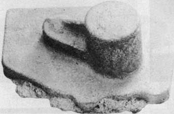
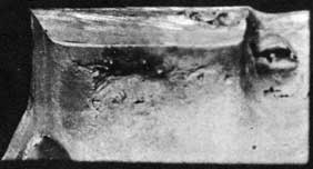
Stickers are often caused by faulty flask equipment. The defective flask prevents a clean pattern draw and, as a result, some sand sticks to the pattern. The sticker shown in figure 198 was caused by loose pins and bushings.
Swells, fins, runouts, bleeders, metal penetration, hot tears, and hot cracks can often be traced to faulty equipment and rigging. Swells and fins are likely to occur when the mold weights are not heavy enough for the casting being poured. Because of the light weight of sand, the molten metal is able to displace the sand and produce a swell in the casting. If this displacement occurs at the parting line or a core print, the molten metal is able to penetrate the joint and a fin is the result. Swells and fins can be remedied by using enough mold weights or clamps to resist the ferrostatic force of the molten metal. Remember that iron, steel, brass, and bronze are heavier than sand, so the cope will tend to float off when these metals are used. For double security, use both mold weights and clamps.
Runouts and bleeder s occur when the molten metal penetrates the parting line and reaches the outside of the mold. A breakout may occur anywhere on the mold and may be caused by insufficient sand between the pattern and the flask, or by soft ramming. Runouts and bleeders at the parting line are often caused by uneven matching of the cope and drag. This mismatch may be caused by bad pins and bushings, dirt in the flask joint, bad bottom boards, or uneven clamping. The cures are self-evident.
Metal penetration (rough surface of the casting) is caused by ramming the mold too soft, as when there is too little space between the pattern and the flask. A larger flask will permit harder ramming between the pattern and the flask and reduce penetration of the metal between the grains of sand.
Hot tears and hot cracks can often be traced to a lack of collapsibility in sand which has been excessively reinforced. Excessive reinforcement prevents the sand from collapsing and obstructs free contraction of the casting. Remember that metals contract when they solidify and that the mold must be weak enough to allow the casting to contract. If the mold is too strong, the casting may crack. Reinforcement which is placed too near a sprue or riser has an even greater effect than that mentioned above. The reinforcement in this case restrains the sprue and riser from any free movement with the casting and is almost sure to cause hot tears or hot cracks. If hot tears or hot cracks occur near the point where risers or sprues are attached to the casting, the reinforcement of the mold should be checked as a possible cause.
GATING AND RISERING
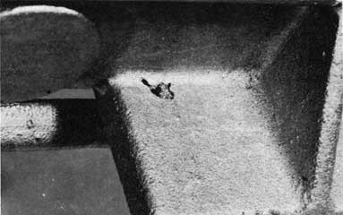
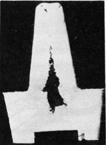
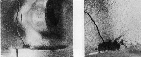
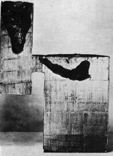
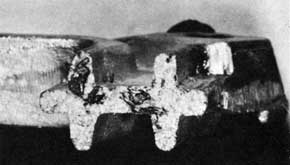
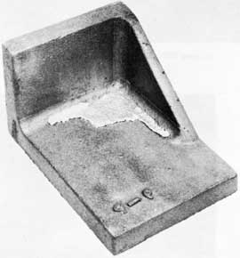
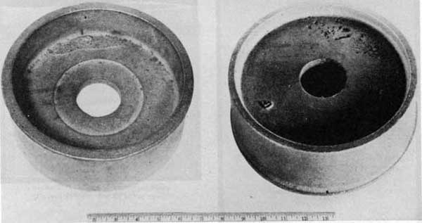
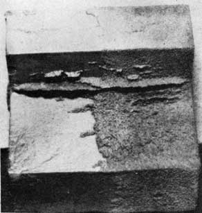
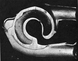
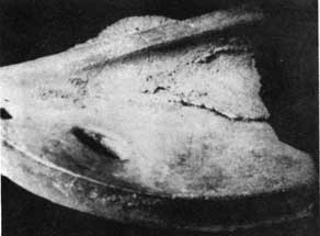
Shrinkage cavities, inclusions, cuts, and washes are the defects most frequently caused by gating and risering. If a riser is too small for the section to be fed, there will not be enough metal to feed the section and a shrink will occur in the casting. The gross shrink shown in figure 199 was caused by inadequate feeding. Surface shrinks caused by improper feeding are shown in figures 200 and 201. Improper location of gates and risers for directional solidification can also lead to shrinks. Figure 202 shows an internal shrink which was exposed when the riser was removed. This defect resulted from an improper gating system which resulted in cold metal in the riser. When the casting was gated so as to put hot metal in the riser (as shown in figure 203), the shrink defect was eliminated.
Connections which freeze off too early between a riser and casting produce a shrink by the same method as a small riser because there is no molten metal available to feed the casting. In such a case, the connections should be made larger. The location of the riser with respect to the section it is feeding can also cause a shrink as shown in figure 204. In this casting, the location of the ingate prevented proper feeding of the casting even though the riser contained molten metal.
Inclusions are caused when the gating system permits dirt, slag, or dross to be carried into the casting. The method of eliminating
152
inclusions is to provide a choking action at the base of the sprue by using a tapered sprue of correct cross-sectional area. If it is impossible to provide proper choking action in the gating system, a skim core should be used at the base of the sprue to trap dirt and slag. Dross inclusions in a fractured aluminum casting are shown in figure 205.
Cuts and washes are defects which are also caused by the gating system. lithe ingates of a mold are located so that the metal entering the mold impinges or strikes directly on cores or a mold surface, the sand will be washed away by the eroding action of the stream of molten metal. The defect will then appear on the casting as a rough section, usually larger than the designed section thickness. Sand inclusions are usually associated with cuts and washes as a result of the sand eroded and carried to other parts of the casting by the stream of metal.
Improper risering and gating can also cause blows, scabs, metal penetration, hot tears, hot cracks, swells, fins, shifts, runouts, bleeders, misruns, and cold shuts. Blows or gas holes are caused by accumulated or generated gas or air which is trapped by the metal. They are usually smooth-walled rounded cavities of spherical, elongated, or flattened shape. If the sprue is not high enough to provide the necessary ferrostatic heat to force the gas or air out of the mold, the gas or air will be trapped and a blow will result. An increase in the height of the sprue or better venting of the mold are cures for a blow of this type. A similar blow may also occur if the riser connection to the casting freezes off too soon and the metal head in the riser is prevented from functioning properly. To cure this situation, the connections should be made larger, placed closer to the casting, or the connection area should be checked for possible chilling from gaggers or improperly placed chills.
Scabs can be caused by the gating system if the gating arrangement causes an uneven heating of the mold by the molten metal. The cure for a scab from this cause is to regate the casting to obtain a uniform distribution of metal entering the mold.
Metal penetration (rough surface on the casting) occurs if the sand is exposed to the radiant heat of the molten metal for too long a time so that the binder is burned out. An increase in the number of ingates to fill the mold more rapidly will correct this situation. Any gating arrangements which cause the sand to be dried out by excessive radiation will result in metal penetration. A sprue which is too high will cause a high ferrostatic pressure to act on the mold surfaces and cause metal penetration. Metal penetration of this type can be cured by decreasing the height of the cope.
The location of gates and risers can cause hot tears and hot cracks. If the gates and risers restrict the contraction of the casting, hot tears and cracks will occur. If the defects are near the ingates and risers, this cause should be investigated as a possible trouble spot.
Swells, fins, runouts, and bleeders may also be caused by improper gating. Risers which are too high cause an excessive ferrostatic force to act on the mold, with the result that these defects occur. A reduction in cope height will correct defects of this type. Run-outs and bleeders may also occur if any part of the gating or risering system is too close to the outside of the mold. In such a situation, there is insufficient sand between the gates, runners, risers, and flask to permit proper ramming. This results in weak sand which cannot withstand the force of the molten metal. The selection of flasks of proper size for the casting being made is the method of overcoming these defects.
Misruns and cold shuts are caused by any part of the gating and risering system which prevents the mold from filling rapidly. Gates or runners which are too small restrict the flow of molten metal and permit it to cool before filling the mold. Improperly located in-gates will have the same result. If the pressure head of a casting is too low, the mold will not fill completely and a cold shut will result. Increasing the size of the gating system and relocation of ingates are methods used to correct defects due to the gating system. Increasing the height of the sprue will produce a greater pressure head and help to fill the mold rapidly.
SAND
By itself, the molding sand can cause all of the casting defects that a molder will encounter. This is one of the reasons that it is difficult to determine the cause of some defects. Blows can be caused by sand that is too fine, too wet, or by sand that has low permeability so that gas cannot escape. If the sand contains clay balls because of improper mixing, blows will be apt to occur because the clay balls are high in moisture. A blow caused in an aluminum casting by high moisture content of the sand is shown in figure 206. To remedy this situation, the sand should be mulled to break up the clay balls. If the sand contains too many fines, it will have a low permeability and the moisture or gas will have a difficult time flowing through the sand away from the casting. Fines should be reduced by adding new sands.
Too high a moisture content in the sand makes it difficult to carry the excessive volumes of water vapor away from the casting. Use of
153
the correct moisture contents and the control of moisture content by routine tests with sand testing equipment is the best way to correct this cause. When the permeability of sand is low, it is difficult for even small amounts of moisture to escape through the sand. The addition of new sands and a reduction in clay content serve to "open up" a sand and increase its permeability.
Drops are often caused by low green strength. Such sand does not have the necessary strength to maintain its shape, so pieces fall off. Corrective measures call for an increase in binder, increase in mixing time, or an increase in both binder and mixing time. Don't overlook the possibility of reinforcing a weak section of a mold with wires, nails, or gaggers.
A scab will be caused on a casting when the sand mold cannot expand uniformly when it is heated by molten metal. The individual sand grains have to expand. If the mold does not "give," the surface of the mold has to buckle and cause a scab. An expansion scab is shown in figure 207. The main cause of a sand being unable to expand properly is the presence of too many fines in the sand. These fines cause the sand to pack much harder so that its expansion is restricted. Addition of new sands to properly balance the sand grain distribution and reduce the percentage of fines is used to obtain better sand properties. Another remedy is to add something to the sand to act as a cushion. Cereal flour, wood flour, and sea coal are all used for this purpose.
A molding sand may y have acceptable thermal-expansion properties, but a low green strength may also cause an expansion scab. The cure in this situation is to increase the clay content. A high dry strength and a high hot strength can also cause expansion scabs. The sand will be too rigid because of the high strengths, and proper expansion of the sand will be restricted. A reduction in the clay or binders which cause the high strengths will correct scabs due to these causes. If a scab is present on a casting surface where sand shakeout and cleaning was difficult, high hot strength of the sand was probably the cause. The binder should be reduced, cushioning materials added, or fines reduced by adding coarser sand.
The principal cause for cuts and washes is low hot strength. When the sand is heated by the molten metal, it does not have the necessary strength to resist the eroding action of the flowing metal and is washed away. If an increase in the amount of binder does not cure cuts and washes, a different type of binder may be required. An addition of silica flour may also be used to correct low hot strength. A low
green strength and a low dry strength may also lead to cuts and washes. These properties are corrected by increasing the binder. A defect closely related to cuts and washes is the erosion scab. It is also caused by a molding sand having a low hot strength. A combination of other factors such as high moisture and hard ramming can also cause an erosion scab such as shown in figure 208. Hard ramming makes the escape of moisture difficult when hot metal is poured into the mold. As a result, the expanding vapor loosens the sand grains and they are washed away by the molten metal. Sand inclusions in some part of a casting are always found when expansion scabs occur.
A metal-penetration defect occurs when the molten metal penetrates into the sand and produces an enlarged, rough surface on the casting. If the metal penetration is not too deep, it may have the appearance of a swell. Coarse sand, high permeability, and low mold hardness are the principal sand properties which cause metal penetration. A sand that is too coarse will have larger openings between sand grains (this accounts for the high permeability). Because of the openings, the molten metal does not have any difficulty in penetrating into the sand. A low mold hardness is caused by soft ramming of the mold. This condition offers a soft surface to the molten metal which, again, can easily penetrate into the sand. To correct penetration due to coarse sand and high permeability, fine sand must be added to the base sand to get a finer sand distribution and reduce the permeability. Harder and improved ramming technique is the cure for metal penetration caused by low mold hardness. If permeability of the sand cannot be reduced, a mold wash may be used to eliminate penetration. An example of metal penetration is shown in figure 209. The left side of the casting has a good surface - the result of using a mold wash to prevent penetration.
Veining is shown in figure 209. It is caused when the sand cracks and the crack is filled by the molten metal. A sand that collapses rapidly under the heat of molten metal will produce veining. This can be corrected by the addition of more binder or silica flour to the sand.
Hot tears and hot cracks are usually caused by poor sand properties. A high percentage of fines and a high hot strength are the principal causes. A high percentage of fine sand grains produces a more closely packed sand, with the result that it cannot contract properly when the casting itself contracts during and after solidification. The reduction of fines can be accomplished by additions of coarse sand. A high hot strength will also prevent the sand from contracting or collapsing properly. A reduction in the content of fines is also a corrective measure
154
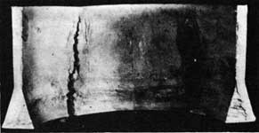
for hot cracks and tears due to a high hot strength. A reduction in the binder content may be required to correct a high hot strength. A severe hot tear is shown in figure 210.
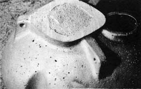
Pinholes are caused by a high moisture content in the sand. Pinholes are recognized by their small size and location on the casting surface as shown in figure 211. The cure for pinholes is to use the correct amount of moisture. This can be determined by proper sand testing and control. There are other minor causes of pinholes, but high moisture content in the sand is by far the greatest source of trouble.
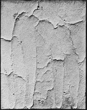
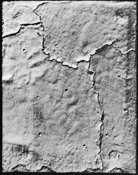
An expansion of the sand so that a part of the mold surface is displaced in an irregular line produces a rattail defect. These defects are shown in figures 212 and 213. Rattails do not always occur as severely as shown in these two examples. They may be as fine as hairlines on the surface of a casting. A sand of improper grain size distribution, high hot strength, and that has been rammed hard are the major contributing causes to rattails. To cure this situation, greater care must be taken to ram the mold to make a uniform mold surface of correct hardness. The high hot strength can be corrected by reducing the binder. Better expansion properties can be obtained by proper grain size distribution in the sand, or by adding cushioning materials.
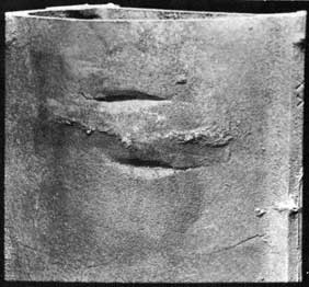
Buckles are similar to expansion scabs and rattails. When an expansion scab is removed from the surface of a casting, an indentation in the casting surface will be revealed. This indentation is a buckle and is shown in figure 214. A rattail is sometimes called a minor buckle. The cure for a buckle is the same as for an expansion scab.
Stickers due to sand are caused by too high a moisture content or by a low green strength. A high moisture content will cause the sand to stick to the pattern. A reduction in the moisture content is necessary to overcome stickers from this cause. If the green strength is low, the sand will not have the necessary strength to permit drawing from a pocket or along a vertical surface. Additions of binder or improvement of the mixing procedure by using a muller to produce a more uniform distribution of binder are corrective measures which can be taken to eliminate stickers of this type. Proper use of parting compounds will minimize sticking.
CORES
The molding sand conditions which contribute to casting defects also apply to cores. Among these conditions are low permeability (which causes blows), low binder content (which
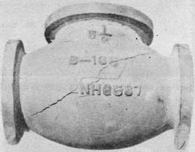
leads to cuts and washes), and hot tears (which are caused by cores having low collapsibility). Figure 215 shows a casting that cracked because the core was too hard.
The baking of cores can also cause casting defects. An underbaked core will still contain a large amount of core oil, which may cause a blow when the casting is poured. Such a blow can be cured by baking the core properly and by using the correct amount of binder.
Overbaking of cores causes defects because it results in burned-out binders. An over-baked core will have a weak and soft surface. Cuts, washes, and metal penetration result from overbaking. Correct baking time for the type of binder used and for the size of the core is the method for correcting these defects.
Another contributing factor to the occurrence of hot tears may be over-reinforcement. This is especially true of larger cores where reinforcement is necessary. The use of reinforcing wires and rods only when they are required and only in amounts necessary is the way to overcome hot tears from over-reinforcement.
Core shifts cause runouts, bleeders, misruns, coldshuts, and castings that are dimensionally inaccurate. If cores are improperly fitted in the core print, molten metal can run in between the core and the mold and cause a bleeder or runout. Molten metal may also fill the vent and cause a blow. Incorrectly pasted cores, cores with vents too close to the surface, and cores with inert backing material too close to the surface provide an easy path for the molten metal to run out of the mold. Correct fitting and pasting of cores, relocation of vents toward the center of the core, and central location of inert backing material are the steps required to correct runouts and bleeders from these causes. A core shift may reduce the section thickness of a mold with the result that the section will not be completely filled. A misrun caused by a core shift is shown in figure 216. To correct such a defect, it is necessary to provide better support for the core, either by a better-designed core print or by the use of chaplets.
MOLDING PRACTICE
Molding practice, along with the other operations involved in foundry work, contributes to casting defects if not properly done. Blows are caused by a combination of hot sand and cold cores and flasks. This combination causes moisture to condense and to give a localized concentration of moisture which causes a blow. To prevent this type of blow, sand should be cool before making a mold. Do not use hot sand.
155
Hard ramming of the sand can cause blows and expansion scabs as shown in figure 217. The blows occur because moisture is prevented from escaping by the closely packed sand. Expansion scabs occur because the hard rammed sand expands and buckles. The casting shown in figure 217 was of such a design that hard ramming could not be avoided. In this case, wood flour additions were made to provide a cushion for the hard rammed sand so that it would expand without buckling.
Figure 218 shows a sticker that was caused by hard ramming in the pockets. Improved technique corrected this defect.
Metal penetration can take place because of soft or uneven ramming, which produces a soft mold surface. Harder and more uniform ramming is the cure for this type of defect. Soft ramming may also result in swells or fins. The sand is soft at the mold surface and cannot retain its shape against the pressure of the molten metal, with the result that the mold cavity is forced out of shape and the defect occurs.
Poor molding practice is probably the major cause for crushes. Careless closing of a mold will result in displaced sand or cores, which in turn result in the crush. If the bottom board is not properly bedded, a high spot of sand on the board will cause pressure against the mold and a displacement of sand in the mold cavity. This again will cause a crush. Incorrectly placed chaplets, or chaplets of incorrect size, will also result in pressure being exerted either on the mold or on the core and cause a crush. Any defect due to poor molding practice can be corrected by only one method; improve the molding technique. Care and attention to the various operations involved can go a long way toward minimizing defects caused by molding practice.
POURING PRACTICE
The defects caused most often by pouring practice are blows, misruns, coldshuts, and slag or dross inclusions. Blows are caused by using green ladles or ladles with wet patches. Severe blows caused by use of a green ladle are shown in figure 219. A defect from this cause is remedied by using ladles which are thoroughly dried after lining and after any patching is done. Misruns and cold shuts are caused by pouring when the metal is too cold or by interrupting the pouring of the mold. With immersion and optical pyrometers in proper operating condition, misruns and coldshuts due to cold metal are minimized. If either of these defects occur when temperature readings indicate hot metal, a defective instrument is indicated. Sometimes
more than one ladle of metal will be required to pour a mold. In such a case, pouring with the second ladle should start- before the first ladle has been emptied. Otherwise the short interval allowed for the start of pouring from a second ladle is sufficient to chill the metal in the mold and to cause a cold shut, or slag inclusions.
Slow pouring may produce uneven heating of a mold surface by the radiant heat from the molten metal and cause a scab. Faster pouring will fill the mold more rapidly and minimize the radiant heating effects in the mold cavity.
Pouring should always be as fast as the sprue will permit. if a slower or faster pouring rate is indicated, a different sprue size should be used.
Pouring from high above the mold results in an increased metal velocity in the mold until the sprue is full and can lead to washing defects. Also, pouring from a ladle which is held high above the mold permits easy pickup of gases by the molten metal, as well as agitation in the stream of metal.
MISCELLANEOUS
The use of rusty or damp chills and chaplets almost always causes blows. The rust on chills and chaplets reacts readily with the molten metal and a large amount of gas is produced in the casting at this point. The localized high gas content cannot escape and a blow is produced. A similar situation is brought about by the use of damp chills or chaplets. The moisture on the chills or chaplets forms steam which results in a blow. Figure 220 shows a blow which was caused in an aluminum casting by using a bad chill.
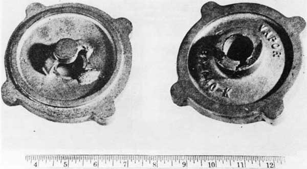
Careless handling of a mold can result in wasted effort on the part of the molder. Rough treatment may result in drops. The careless placing of mold weights can also result in drops from excess pressure on the cope. A drop due to rough handling of the mold is shown in figure 221. The left side of the figure shows the cope side of the casting. The rough lump of metal which filled the cavity by the displaced sand can easily be seen. The right side of the figure shows the drag side of the casting with the hole at the center core caused by the sand which dropped from the cope. The sand that dropped may float in heavy metal castings and cause a second defect in the cope.
Cracks and tears can be caused by shaking out the casting too early. This causes chilling of the casting and high stresses are produced. The casting usually has a low strength when hot. Dumping of hot castings into wet sand can also cause cracks and tears. Careless grinding of
156
the casting may cause localized overheating, high stresses, and cracks. See Chapter 10, "Cleaning Castings," for correct grinding techniques.
The use of moist, dirty, or rusty melting tools may cause the introduction of moisture into the melt. This source of moisture can result in pinholes in the completed casting. Every effort should be made to maintain good melting practice to prevent the rejection of casting because of carelessness in the melting operation.
SUMMARY
When determining the cause of casting defects, it must always be kept in mind that defects are more often due to a combination of causes rather than to one isolated cause. The use of properly kept records of previous castings, good sand control, and development of a good molding procedure can go far in making the job of eliminating casting defects an easier one. A chart has been included which indicates the causes of the various defects and possible cures and should be used as a convenient reference.
The following oversize tables are on separate pages.
Summary of Casting Defects - Page 157
Summary of Casting Defects - Page 159
Summary of Casting Defects - Page 161
Summary of Casting Defects - Page 163
Summary of Casting Defects - Page 165
Summary of Casting Defects - Page 167
Summary of Casting Defects - Page 169
Summary of Casting Defects - Page 171
173
Figure 198. Sticker. (Caused by loose pins and bushings)
Figure 200. Surface shrink. (Caused by improper feeding)
Figure 199. Gross shrink. (Caused by inadequate feeding)
Figure 201. Surface shrink. (Caused by improper feeding.)
(Crack resulted from breaking the casting for examination.)
174
Figure 202. Internal shrink.
(Caused by cold-metal riser arrangement)
Figure 203. Gating and risering that corrected internal shrink in figure 202.
Figure 204. Gross shrink.
(Caused by improper location of ingate.)
Figure 205. Gross inclusions.
(Revealed by fractured aluminum casting)
Figure 206. Blow. (Caused by high moisture content)
Figure 207. Expansion scab. (Caused by too many fines in the sand)
175
Figure 208. Erosion scab and inclusions.
Figure 209. Metal penetration and veining. (Penetration caused by an open sand veining caused by metal penetration into cracked sand)
Figure 210. Hot tear. (Caused by too high hot strength of the molding sand)
Figure 211. Pin holes. (Caused by high moisture content of the sand)
176
Figure 212. Rattails. (Sand lacked good expansion properties)
Figure 213. Rattails. (Cause same as for Fig. 207)
Figure 214. Buckle.
Figure 215. Cracked casting. (Caused by a hard core)
Figure 216. Misrun. (Caused by a core shift)
177
Figure 217. Blow and expansion scab. (Caused by hard ramming of the sand)
Figure 218. Sticker. (Caused by hard ramming in pockets)
Figure 219. Blows. (Caused by moisture pickup from a damp ladle)
178
Figure 220. Blow. (Caused by a bad chill)
Figure 221. Drop. (Caused by rough handling of the mold)
179
Chapter XII HEAT TREATMENT OF CASTINGS
The most common types of heat treatment applied to castings are as follows:
IRON AND STEEL CASTINGS
STRESS-RELIEF ANNEAL
Low-temperature treatment to improve dimensional stability and increase available strength by decreasing residual stresses. Can be applied to all castings. Requires slow cooling in the furnace. Usually has little effect on hardness.
FULL ANNEAL
High-temperature treatment to homogenize the cast structure. Improves mechanical properties or machinability. Required for steel castings that are not normalized. Desirable for cast iron where "chill" is present and castings must be machined. Requires slow cooling in the furnace.
NORMALIZE
High-temperature treatment for steel castings that are not annealed. Improves structure and ductility. Requires cooling in air.
TEMPER
Low-temperature treatment following normalizing or quenching. Similar to stress-relief anneal but involves cooling in air. Results in softening of normalized steel or iron castings.
QUENCHING
Fast cooling of castings from high temperatures by immersing them in quenching oil, water, or brine. Results in hardening of iron and steel castings. Involves considerable risk of cracking the casting. Details of quenching are outside the scope of this manual. Quenching must almost always be followed by tempering.
NONFERROUS CASTINGS
STRESS-RELIEF ANNEAL
Low temperature treatment to improve dimensional stability and increase the available strength by decreasing residual stresses. Can be applied to all castings. May increase the
hardness. Temperature and time of treatment depends on the particular alloy.
SOLUTION HEAT TREATMENT
High temperature treatment. Usually for aluminum for prolonged periods, generally just below the solidus temperature to homogenize the structure, followed by quenching in warm water. Temperature and time of treatment depends on the particular alloy. This treatment produces the softest most ductile condition. It is generally followed by artificial aging.
AGING
A low temperature treatment following solution heat treatment to produce maximum hardness and yield strength.
REASONS FOR HEAT TREATMENT
There are several reasons for heat treating castings. The properties of some alloys such as heat-treatable bronzes, heat-treatable aluminum alloys, various steels, and cast irons can be improved by heat treatment. Improvement of mechanical properties is the main reason for the heat treatment of castings.
A second important reason for heat treatment is for the removal of residual stresses that are the result of casting design, solidification, or lack of free contraction because of sand properties. See Chapter 1, "How Metals Solidify," Chapter 2, "Designing a Casting," and Chapter 4, "Sand for Molds and Cores." Stress-relief heat treating involves heating followed by slow cooling.
Another reason for heat treating is to make ferrous castings softer than they were in the as-cast condition, so that they will be easier to machine. Also, it may be necessary to reduce the hardness that may have been caused by chilling, such as may occur with gray irons. Such heat treatment is called annealing.
Because of the slow cooling in sand, many castings will have a coarse grain structure that does not provide the best properties. This can be corrected by a heat treatment that will cause the solidified metal to recrystallize and form smaller grains. This recrystallization will produce improved properties in the casting.
In many alloys, it is difficult to produce a uniform structure in the casting because of the
452605 0-58-12
180
alloy itself, or because of the conditions controlling solidification of the casting. In such a case, heat treatment can be used to obtain a uniform homogeneous structure.
All of the changes in properties obtained by heat treating of metals or alloys depend on the movement of the atoms of metal. When a metal or alloy solidifies, it forms in a definite pattern of atoms. This pattern determines its crystal structure. Heat treatment often produces a rearrangement of the atoms to produce the desired properties. Movement of the atoms to accomplish this rearrangement is called diffusion.
Diffusion takes place in a metal or alloy when it is heated to a certain critical temperature which permits the easy movement of the various atoms. This critical temperature at which rapid diffusion starts is known as the activation temperature. Below this temperature, diffusion does take place but is so slow that heat treatment at these lower temperatures would be impractical. The old-fashioned practice of "aging" castings for months by storing them at room temperature is an example of a low temperature heat treatment which requires a long time, but which can be speeded up to a matter of several hours by proper heating of the casting.
A simple example of diffusion and the effect of temperature can be shown with water and a dye. If the water is frozen into ice and a drop of dye placed on its surface, the dye will maintain its drop shape and possibly penetrate a very short distance into the ice. With the application of heat, the ice will reach its melting point. As it melts, the dye can be seen moving through the water and tinting it. This movement of the dye is diffusion. The melting temperature of the ice (which resulted in water) is the activation temperature.
The process by which the atoms diffuse to produce smaller grains is known as recrystallization. The formation of the new crystal takes place at nuclei which may be centers of high concentration of a particular element, impurities in the metal, ideal atom arrangements, or even centers of high stress in the casting. Whatever their cause, they serve the same purpose as the nuclei described in Chapter 1, "How Metals Solidify." They act as centers of crystal growth. The only difference between recrystallization and solidification, so far as crystal growth is concerned, is that during solidification the atoms form the crystals from a liquid state and in re-crystallization, the new crystals are formed by the diffusion of the atoms through the solid metal.
In the heat treatment of most alloys, a preliminary step known as solution treatment is necessary. Solution treatment means to change the state of the alloy into that of a solid solution. A solid solution alloy is one in which the alloys are soluble in each other in the solid state. Under a microscope, a solid-solution alloy would have the appearance of a pure metal. It would be uniform, without any indication of the presence of more than one metal. This would be in contrast to other alloys in which the presence of more than one alloy is shown by two or more characteristic phases.
BRASS AND BRONZE
There are only a few copper-base alloys that can be heat treated to improve their mechanical properties. For most copper-base alloys only a stress-relief annealing treatment is used to remove residual stresses.
STRESS-RELIEF ANNEAL
Tin-bronzes can be stress relieved by heating at a temperature between 700°F. and 800°F. for at least 1 hour. The castings are then cooled in air from this temperature. Where extreme dimensional stability is required, the casting should be rough machined before stress relieving.
Manganese-bronze can be stress relieved by heating in a temperature range of 600-800°F. (1 hour for each inch of casting thickness) and air or furnace cooling.
Copper-base castings in general can be stress relieved by heating at 700°F. to 800°F. (one hour for each inch of casting thickness) and then cooled in air.
SOFTENING AND HARDENING
Certain aluminum-bronze alloys can be heat treated to obtain higher strength and hardness. This heat treatment consists of softening the alloy by a solution heat treatment, followed by an aging treatment that hardens it to the desired strength. Classes 2, 3, and 4 aluminum-bronze alloys fall into this group. The exact heat-treating cycle is determined by the composition of the alloy and the properties desired. Castings should be heated to a temperature between 1,600°F. and 1,650°F., water quenched, and aged between 1,000°F. and 1,150°F. A good general rule for holding time at the heat treating temperature is to hold for 1 hour for each inch of section thickness.
181
ALUMINUM
STRESS-RELIEF ANNEAL
Aluminum alloys are not usually heat treated for removal of casting stresses. When it is desirable to reduce the residual stresses in an intricate casting so as to make it stronger, less susceptible to cracking, or more stable dimensionally, heat the casting to about 600°F., hold it from two to seven hours, and then air cool. (T2). Additional data is given under "General Heat Treatments."
GENERAL HEAT TREATMENTS
Aluminum alloys in classes 1, 3, 4, 7, and 8 can be heat treated. The heat treatment involves a softening of the alloys by a solution heat treatment followed by quenching in warm water followed by an appropriate aging treatment to harden it.
Exact information on heat-treating procedures should be obtained from the Bureau of Ships.
Some typical heat treatments of aluminum casting alloys are as follows:
GENERAL HEAT TREATMENT OF ALUMINUM ALLOYS
Alloy Type
Condition Desireda
Solution Heat Treatment
Aging
Annealing
Time at Temp. hours
Temp.b F.
Quenching Media
Time, hours
Temp.b F.
Time, hours
Temp.b F.
Aluminum- Silicon
T2
(Not heat treatable and seldom used)
--
--
2 to 4
600
Aluminum- Copper (or Al- Cu-Si)
T4
12
960
Boiling water
--
--
--
--
T6
12
960
Ditto
3 to 5
310
--
--
Aluminum- Magnesium
T4
12
810
Ditto
--
--
--
--
Aluminum- Magnesium- Silicon
T5
--
--
--
--
--
7 to 9
440
T6
12
980
Boiling water
3 to 5
310
--
--
T7
12
980
Ditto
--
--
7 to 9
440
aT2 Annealed.
T4 Solution heat treated for maximum softness and ductility.
T5 Stress relieved.
T6 Solution heat treated and aged for maximum strength and hardness.
T7 Solution heat treated and overaged for maximum dimensional stability combined with good strength and hardness. bFurnaces must generally be air-circulating type and controlled to ±3 F.
IRON AND STEEL
STEEL
Cast steel has a coarse microstructure. Castings placed in service in this condition may fail because of the brittle nature of the material. Therefore, steel castings must be heat treated to refine the grains by recrystallization, to homogenize the structure, and to improve the physical properties. Two types of heat treatment are (1) annealing, and (2) normalizing followed by tempering. Steel castings that have been welded or worked should be stress relieved before use. The details of these treatments are as follows:
Class A castings and Class B castings under Specification MIL-S-15083 shall be annealed or heat treated in accordance with the specification requirements. Heat treatment should be accomplished with adequate and calibrated pyrometric equipment. Castings should be charged so that the lighter castings will be shielded from the heat of the furnace by the heavier castings, placing the casting loosely and, if possible, a few inches off the floor of the furnace, so that the hot gases will have free circulation throughout the charge. Large castings must be properly supported under heavy sections to minimize distortion.
182
Annealing. Navy specifications for Class B and low-alloy steel castings require that the castings shall be placed in a furnace, the temperature of which is not more than 500°F. above that of the castings and shall be uniformly heated at a controlled rate to a temperature of 1600°F. or above. The castings shall be held at the annealing temperature for a period of at least 1 hour per inch of thickest cross section, but in no case less than 1 hour. The temperature difference between the hottest and coldest part of the charge during the holding period shall not be greater than 75°F. The castings shall be cooled slowly in the furnace from the heat-treating temperature. When the temperature of the hottest part of the charge has fallen to 500°F. above the ambient temperature, the castings may be removed from the furnace and cooled in still air. Where time is a factor, the cooling rate of small castings, such as pipe fittings or those where dimensional stability is not a controlling factor, may be accelerated when the temperature of the casting has fallen to 1000°F.
Normalizing. "The castings shall be heated and held at temperature***" as described under annealing. They shall then be removed from the furnace and permitted to cool through the critical range in still air. The difference between annealing and normalizing should be made clear. In annealing, the casting is cooled slowly in the furnace and is softened. In normalizing, the casting is cooled in air and may be hardened. Normalizing must be followed by tempering. Annealed castings are not tempered.
Tempering Heat Treatment of Normalized Castings. Castings which have been normalized shall be given a tempering heat treatment by heating in accordance with the requirements given under annealing until the temperature of 1000° to 1250°F. is reached. The temperature of the charge shall remain within this range for a period of not less than 1 hour for each inch or fraction thereof of maximum thickness of section. The castings shall be cooled in air from the heat-treating temperature.
Certain steels develop a brittleness characterized by loss of ductility and impact strength when held for excessive times or slow cooled through temperature ranges of about 400° to 700°F. and 850° to 1100°F. The causes of this "temper brittleness" are not well understood. Fine-grained aluminum-killed steels are less susceptible to temper brittleness than coarse grained silicon-killed steels.
Stress-Relief Heat Treatment. Castings which have been subjected to cold straightening, welding, or forming shall be given a stress-relief heat treatment identical with the tempering heat treatment of normalized castings described.
Bend Test. A bend test may be used as a shop test for checking the quality of a steel and the effectiveness of heat treatment. Bend-test specimens are machined to about 6 inches long with a rectangular cross section of 1 by 1/2 inches and with the long edges rounded to a radius of not over 1/16 inch.
A rectangular bar which has been adequately gated and risered to ensure soundness and which is suitable for machining to the above dimensions should be poured from each heat of steel. The bend-test bar should be given the same heat treatment as that used for the castings and then machined.
If the steel has been properly made and heat treated, the specimen should withstand cold bending around a 1-inch-diameter pin through an angle of approximately 120°F. without c racking. This is an indication of satisfactory ductility.
CAST IRON
Stress-Relief Annealing. When gray iron castings are removed from the mold, they contain temperature gradients caused by nonuniform cooling of uneven section thicknesses within the casting. This uneven cooling causes internal stresses in the castings. These residual stresses should be relieved by heat treatment, particularly for gray iron castings which require good dimensional stability. A proven practice is to heat slowly and uniformly to 800° to 950°F., hold at temperature for 1 hour per inch of thickness (heaviest section), and cool slowly in the furnace. This treatment, if carried out properly, will not appreciably affect the strength or hardness of the castings. For machinery castings where dimensional stability is important, it may be advisable to rough machine before stress relieving. Then, the heat treatment will relieve internal stresses which may have been introduced as a result of severe rough machining operations.
Annealing. Occasionally, an "off-analyses" heat or a chilled casting maybe produced which will be difficult to machine. As an emergency measure, annealing may be used to soften the casting and improve the machinability. The annealing temperatures will vary. If chilled or white iron interferes with machinability, it may be necessary to anneal the casting at 1700°F. and cool it slowly in the furnace to restore machinability. If chill is not present, machinability can be improved by annealing at 1400°F. and cooling slowly in the furnace.
CAUTION: Annealing gray iron castings will cause softness and lower physical properties.
183
MONEL
It may be necessary to soften "S" Monel to permit easier machining. Annealing consists of heating at a temperature of 1600°F. for approximately 1 hour and air cooling to 1300°F., in a reducing atmosphere followed by either quenching in water or oil. The castings should be heated rapidly to the desired temperature and held for a minimum time to prevent excessive grain growth. CAUTION - The furnace atmosphere must be reducing and free of sulfur, and quenching oil must not contain over 0.5 percent sulfur. Sulfur is very easily picked up by the monel at the high temperatures, and it is detrimental to the physical properties. Severe intercrystalline attack will occur if the furnace atmosphere fluctuates between reducing and oxidizing. Very intricate castings should be quenched in oil.
Water quenching produces a slightly softer condition than oil quenching. If a casting is simple in shape and maximum softness is desired, it is sometimes possible to quench directly from the 1600°F. annealing temperature.
After machining, the casting can be age-hardened by heating at a temperature of 1100°F. for 4 to 6 hours and cooling in air. This treatment produces a hardness as high, or higher, than the as-cast alloy.
SUMMARY
In the heat treatment of castings, it must be remembered that the section size of the casting has an important effect on the properties obtained. (Refer to Chapter 2, "Designing a Casting.") The best mechanical properties are usually obtained in thin sections. A step-bar casting is useful for determining the effect of section size on the properties obtained by heat treatment.
Slow heating, holding for the correct length of time at temperature, and control of the heat-treating temperature by the use of properly operating pyrometers are the most important steps to watch in the heat treating of castings. A good casting can be ruined by slipshod heat treatment. For general information, the various temperatures for heat treatment are summarized in table form.
Alloy
Heat Treatment*
Stress Relief (To relieve residual stresses)
Anneal (To homogenize and to soften reduces strength)
Solution Treatment (softens)
Aging Treatment hardens)
Copper base (general) Tin-bronze
Hold(1) at 700°F. to 800 F., air cool.
--
--
--
Manganese bronze
Hold(1) at 600°- 800°F. air or furnace cool.
--
--
--
Aluminum bronze class 2 and 4
Hold(1) at 1600°F. to 1650°F., water quench.
Hold(1) at 1100°F. to 1150°F., water quench.
class 3
Hold(1) at 1600°F. to 1650 F.,water quench.
Hold(1) at 1000°F., air cool.
Nickel bronze
1400°F. oil quench(2).
500°F., to 600°F. (5 hours).
Aluminum base (general)
600°F. to 800°F. (1 hour).
--
--
--
Class 3, 4, and 7 (Exact treatment can be obtained from BuShips)
--
--
960°F. to 1000°F., quench(2).
310°F. to 475°F.
"S" Monel
Hold(1) at 1600°F., air cool to 1200 F., water or oil quench(2).
Hold(1) at 1100°F. 4 to 6 hours air cooled.
184
Alloy
Heat Treatment*
Stress Relief (To relieve residual stresses)
Anneal (To homogenize and to soften reduces strength)
Solution Treatment (softens)
Aging Treatment hardens)
Cast iron
Hold(1) at 800°F. to 950°F., furnace cool.
Hold(1) at 1700°F., furnace cool ( for chill removal).
--
Hold(1) at 1400°F., furnace cool (improve machinability).
Steel, Class R and low alloy.
Hold(1) at 1100°F. or higher, furnace cool.
Hold(1) at 1600°F. or higher, furnace cool.
Hold(1) at 1650°F. to 1750°F, cool in still air.
Hold(1) at 1100°F. to 1250°F., furnace cool.
*CAUTION: The temperatures listed are only approximate and intended as a guide.
Hold 1 hour for each inch thickness of heaviest section. Minimum time is 1 hour. 2Exact procedures should be obtained from the Bureau of Ships. Poor practice will result in cracked castings. Aluminum is generally quenched in boiling water to minimize danger of cracking.
185
Chapter XIII COMPOSITION OF CASTINGS
The selection of the metal or alloy to be used for a casting is usually specified by the ship requesting the work. Whenever there is any doubt about the metal or alloy to be used, the blueprints of the part found aboard the ship originating the work order should be referred to. The blueprints specify the metal or alloy which provides the best combination of properties for that particular casting. If blueprints or other specifications are not available, and if the selection of the metal for a casting must be made locally, the metal should be selected on the basis of information given in this chapter and in the detailed table given at the end of this chapter.
An alloy is a metallic mixture of two or more elements (of which at least one is a metal). The definition of an alloy must be broad and general so that it will include many nonmetallic elements used in alloys. Examples of nonmetallic elements in iron and steel that may be added to obtain desired properties (or which may be present as impurities) are carbon, sulfur, phosphorus, oxygen, and hydrogen.
Many times an alloy will be referred to as a copper-base alloy, nickel-base alloy, etc. Such a reference means that the particular metal mentioned is the principal metal in the alloy. For example, brass is a copper-base alloy; steel is an iron-base alloy. Through usage in the foundry trade, some names have deviated from their intended meanings. This is particularly true with the brass and bronze alloys. Some alloys called brasses, such as red brass, will have a composition which should fall into a bronze classification, and some other alloys called bronzes, such as manganese bronze, are actually brasses.
Definitions of the alloys commonly used in brass and copper foundry work are as follows:
Copper is a commercially pure metal or one which is alloyed with not more than approximately 1 percent of other elements.
Brass is a copper alloy in which zinc is the principal alloying element. Brass usually contains small quantities of other alloying elements. Because of their appearance or some other property, some brasses have become known as bronzes. Examples are leaded bronze and manganese bronze both of which are actually brasses. Nickel silver is also a brass alloy which has been renamed because of its silvery appearance. A nickel silver is a brass in which nickel has been substituted for part of the zinc.
Bronze was originally the term applied to copper alloys having tin as the principal alloying element. Pure bronzes have been modified with other elements to obtain specific properties, and present-day names often include the secondary alloying element in the name (such as phosphor bronze). In some cases, the tin has been replaced as the principal alloying element, but the alloy is still called a bronze. Aluminum bronze, for example, has aluminum as the principal alloying element, and silicon bronze has silicon as the principal alloying element.
SPECIFICATIONS
If the composition of the alloy desired in a casting is not specified by the ship requesting the part, the molder may have a difficult choice to make in selecting the proper alloy for a new casting. A broken casting or another casting of the same type may give valuable information suggesting the alloy to be used. Aluminum is readily distinguished from brass, bronze, iron, and steel by its weight and color. Most brasses and bronzes have a distinctive color. Most irons and steels, except some stainless steels, are magnetic, while nonferrous alloys (and some stainless steels) are nonmagnetic. (Most irons and steels) rust, nonferrous castings and stainless steels do not. An alert observer will distinguish other differences that will be helpful in identifying an alloy in an emergency. After the general type of alloy (cast iron, steel, bronze, or aluminum), has been established, refer to the appropriate chapters (14 to 18) on the selection of the proper alloy. The only proper selection can be made from blueprint information.
Help in selecting the proper alloy for a particular casting may be obtained from tables A and B, in which are listed the common alloys that the repair ship might be called on to cast.
Table A. Compiled Chart of Selected Military and Navy Specifications for Cast Nonferrous Alloys.
Table B. Compiled Chart of Selected Military and Navy Specifications for Cast Ferrous Alloys.
SELECTION OF METAL MIXTURES
When the foundryman has a choice of the alloy to be used for a casting, he should consider
186
using the simplest and most easily cast alloy that will do the job adequately. As a general rule, the alloy that has the lowest tensile strength of a group will be the easiest to cast. For example, hydraulic bronze (ounce metal) with a tensile strength of 30,000 p.s.i. is easier to cast than manganese bronze with a tensile strength of 65,000 p.s.i. Ordinary cast iron is easier to cast than high-strength cast iron. The more simple alloy should be rejected only when it is inadequate because of requirements for strength, corrosion resistance, or special service.
COPPER-BASE ALLOYS
The copper-base alloys that will be of most universal use on shipboard are hydraulic bronze (also known as red brass and ounce metal), gunmetal (a tin bronze known as Composition G), and valve bronze (a leaded tin bronze known as Composition M). The following description will illustrate the common applications for these materials and will show where some of the other copper-base alloys may be required.
Red Brass, also called hydraulic bronze or ounce metal, is suitable for general service and easy to cast. It can be used for valves, small gears, ornamental work, machine parts, and any other parts that do not involve use as a bearing. It can be used for pressure castings up to 350 p.s.i. (MIL-B-16444).
Gunmetal, also called Composition G, is a tin bronze used for parts requiring medium strength and resistance to salt-water corrosion. It has fair machinability. Typical uses are for valve boxes, expansion joints, flanged pipe fittings, gear wheels, condenser heads, water chests, struts, safety valves, and stop valves. It also may be used for bearings and bushings for high-duty work (MIL-M-16576).
Valve Bronze, also called Composition M, is a leaded tin bronze. The lead, as for all leaded brasses and bronzes, is added to improve machinability. This alloy is similar to Composition G except that the tin content has been reduced and lead increased. This results in strength slightly lower than G metal. Composition M may be used in place of G if the physical properties permit. It is a general-purpose bronze used where medium strength and resistance to salt-water corrosion is necessary. It is used for draft gauges, hose couplings, hose fittings, propeller -shaft sleeves, stuffing boxes, and low and medium-pressure valves (MIL-B-16541).
Yellow Brass is a simple high-strength alloy of about 60 percent copper and 40 percent zinc. It has good strength, is tough, and has moderately good resistance to corrosion.
Yellow brass is particularly useful in torpedo-tube castings (MIL-B- 17512).
Commercial Brass can be used where strength and corrosion resistance are not important (as in handrail fittings, instrument cases, name plates, oil cups, and trim). This alloy is essentially a leaded yellow brass to which tin has been added to improve the physical properties and lead added to improve the machinability (MIL-B-17668).
Naval Brass has a composition similar to that of the commercial brass but the tin and lead contents may be lower. It is used as a general purpose brass for applications such as door fittings and frames, pipe flanges, rail and ladder stanchions, and tarpaulin hooks. It has a corrosion resistance slightly higher than that of commercial brass (MIL-B-17511).
Ornamental Bronze is actually a leaded semi-red brass, which because of its color has become known as a bronze. It has excellent machinability and is used for threaded pipe, ornamental and hardware fittings requiring a high finish, and electrical fittings, and may be used for low-pressure valve bodies (MIL-B18343).
Phosphor Bronze is used for castings that require a medium strength and are subject to salt-water corrosion. Typical applications are for gears, bushings, bearings, expansion joints, pump pistons, and special pipe fittings (MIL-B - 16540).
Tin-Nickel Bronze is used where there is a need for an alloy having a lower tin content but a corrosion resistance comparable to hydraulic bronze (MIL-B-17528).
Tinless Bronze, formerly known as X-1 Metal, has good casting properties and excellent machinability. It can be used where good corrosion resistance or good bearing properties are needed but the use of tin must be minimized (MIL-B-16358).
Manganese Bronze is a popular and useful alloy that can be produced in two levels of strength. Low-tensile manganese bronze has a good combination of high strength and good corrosion resistance in salt water. The designation "low tensile" refers to its minimum tensile strength of 65,000 p.s.i., which is low when compared with other manganese bronzes. Typical applications are for crosshead slipper shoes, engine framing, gypsies and capstans for submarines, nonmagnetic structures, periscope supports, propeller blades, hubs, and worm wheels (MIL-B-16443).
187
High-tensile manganese bronze contains more aluminum to give it greater strength. Alloys of this type have strengths comparable to those of mild steels. They are used where strength, toughness, and resistance to corrosion by salt water is required. Typical applications are in framing, gear s, and worm wheels (MIL-B-16522).
Aluminum Bronze has the highest strength, wear resistance, and toughness of any copper-base alloy. By proper attention to casting procedures and heat treatment, tensile strengths of more than 100,000 p.s.i. can be produced. Aluminum and iron are the principal alloying elements. Aluminum bronze can be used in applications similar to manganese bronze. Its uses include gears, pinions, propeller blades, and worm wheels (MIL-B-16033).
Silicon Bronze (copper-silver alloy) has a combination of good casting properties and homogeneous structure. It is used where high strength, toughness, and resistance to corrosion are required. It may be used for pump bodies, marine hardware, and machine parts, and makes excellent bells (QQ-C-593).
Nickel Silver (also known as copper -nickel-zinc alloy) is a copper-base alloy with nickel as the principal alloying element. It also contains additions of tin, zinc, and lead. This alloy has a white color, good corrosion resistance, good mechanical properties, and good tarnish resistance. A typical application is in graduated sight drums for fire-control instruments. It is also used for hospital equipment (MIL-C -17112).
Copper Nickel is a 70 copper - 30 nickel alloy that provides a high grade material for pipe and tube fittings (MIL-C-20159).
Bearing Bronzes are generally special high-leaded tin bronzes. Grade I bearing bronze contains 18 to 21 percent lead. It is sort and is used principally for bearing liners under conditions where the bearing metal is required to deform locally to conform to irregularities of motion or imperfection in fitting. It also supplies reasonable service where it is difficult to lubricate. Typical applications are in bearings for winches and conveyors (MIL-B16261).
Grade II bearing bronze, which is stronger than Grade I, has a lead content of 7 to 9 percent and a tin content of 7 to 9 percent. It is good for general bearing surfaces and fairly good for structural purposes. It is suitable where bearings are cast as a part of supporting or enclosing structures (MIL-B-16261).
Grade III bearing bronze is a hard bearing bronze (tin bronze) also known as hard-gear bronze. Examples of its use are for bushings in ammunition hoists, turret turning gear, winches, and rudder bearing rings (MIL-B-16261).
Grade IV bearing bronze has a lead content of 13 to 16 percent, a tin content of 6.25 to 8 percent, and a zinc content of 0.0 to 0.75 percent. Examples of its use are in low pressure valves and fittings, general hardware, and plumbing supplies (MIL-B-16261).
Grade V bearing bronze has a lead content of 23 to 26 percent and a tin content of 4.5 to 6 percent. Examples of its use are bearings under light loads and high speeds (MIL-B-16261).
Grade VI bearing bronze is a high-leaded tin bronze that contains up to 0.5 percent nickel. It is used wherever high strength, hardness, or shock resistance is required. Bearings made from this alloy are finely finished and installation must be true running for the heavy loads carried. Lubrication is necessary (MIL-B16261).
Grade VII bearing bronze has a lead content of 14 to 16 percent and a tin content of 12 to 14 percent. Examples of its use are for general purpose, low-speed, moderate pressure, bearings (MIL-B-16261).
COPPER CASTINGS
Copper castings are used only for special parts where high electrical or high heat conductivity are required. Castings requiring an electrical conductivity greater than 85 percent must be made from a high-purity copper and only small amounts of deoxidizers maybe used. Electrical conductivity is greatly reduced by even small amounts of tin, silicon, magnesium, or aluminum. Copper castings must be heavily risered because they are subject to high shrinkage during solidification.
NICKEL-BASE ALLOYS
Monel is a nickel-base alloy with copper as the principal alloying element. It has very high corrosion resistance and high strength. It is particularly useful where high corrosion resistance and high strength are needed at elevated temperatures. Typical applications are shaft nuts, shaft caps, high-pressure valves, valve trim, and fittings (QQ-N-00288).
Monel modified by additions of silicon is useful where nongalling and antiseizing properties are required. It is also used for propellers (QQ-N-00288).
188
ALUMINUM-BASE ALLOYS
Aluminum-base casting alloys are widely used because of their light weight. The alloys used for casting aboard ship are of two general groups: (1) those used in the as-cast condition, and (2) those which must be heat treated to obtain the best properties.
Class 2 and Class 5 alloys are used in the as-cast condition. The Class 2 alloy is for general use where maximum corrosion resistance is required, or where an intricate leakproof casting is necessary. Class 5 alloy is used where good tensile strength and corrosion resistance is required. The corrosion resistance is obtained at a sacrifice of tensile strength (MIL-A- 17129).
Aluminum alloys in Classes 1, 3, 4, 6, 7, and 9, require heat treatment to obtain the best properties. See chapter 12 for information on the heat treatment of these alloys. The Class 1 alloy is for general use where high strength, ductility, and resistance to shock are necessary. For castings requiring high quality and excellent fluidity, the Class 3 alloy is used. Its properties include pressure tightness in complex castings, strength, and resistance to corrosion. The Class 4 alloy has higher tensile strength at a sacrifice in corrosion resistance. Typical applications are for ammunition stow-ages, ladder treads, nonmagnetic structures, and sprocket guards. Castings requiring high strength at elevated temperatures can be made from the Class 7 alloy (MIL-A-17129).
LEAD AND TIN-BASE ALLOYS
Babbitt or antifriction metal is a lead or tin-base alloy with antimony or copper as the main alloying element. There are four grades of antifriction alloys generally used in shipboard foundries. Grade 1 is a medium-hard babbitt metal intended for use in aircraft-engine bearings. Grade 2 is a true babbitt metal intended for general use for all bearing surfaces requiring a hard ductile white-metal alloy. Grade 3 is intended for diesel-engine bearings when specifically required. For diesel-engine bearings where loads are excessive and impact is not severe, Grade 4 is used (QQ-T-390).
STEEL
Steel is an iron-base alloy containing a small amount of carbon. Control of the carbon content is vitally important. Low-carbon steels (for example, 0.20 percent carbon) develop little strength but are highly ductile when properly annealed (see chapter 12). High-carbon steels (for example, 0.70 percent carbon) develop higher strength but can be very brittle and difficult to weld if not properly handled. It is best to
keep the carbon content low unless there are special requirements for strength or hardness. Low-carbon alloy steel can be one of the most difficult alloys for the foundryman to cast and heat treat.
Class B Steel is a general-purpose cast steel having a medium tensile strength and high ductility. It has good machinability and good resistance to vibration and shock. Typical applications are for motor bedplates, turbine castings, hoist drums, pipe fittings, struts for shafting, and safety valves. This steel should not be used for temperatures exceeding 650°F (MILS- 15083).
Class A Steel is made in four grades of higher strength and quality than Class B. The improved strength is obtained by a slight increase in the carbon content, by heat treatment, and in certain cases by alloying. Proper heat treatment and tensile testing are requirements for the production of Class A steel. As with Class B steel, the Class A steels are usually not alloyed unless necessary. If the castings are to be welded, hardening alloys such as molybdenum and chromium should be avoided. Class A-70 steel is used for general structural parts. Class A-80 steel is used for castings which are subject to compressive stresses or surface wear (such as may be found in chain pipes, fair leads for anchor cable, followers for piston valves, guides, hawse pipes, and strong-backs). Where greater strength and fair ductility are required, Class A-90 steel should be used. Some typical applications are bearings for turret-turning pinions, carriages for ammunition hoists, rudder crossheads for surface ships, and thrust blocks for turret worm gears. Class A-100 steels are used where maximum strength, hardness, abrasion, and wear resistance are required. The ductility is low (MIL-S- 15083).
ALLOY STEELS
Alloy steel is used for special purposes where some special property is desired. It should not be used except where specified or where it is known that a special property must be developed. These steels are tricky to cast and to heat treat. Improper practice can easily produce an alloy steel which is less satisfactory than a common unalloyed steel.
Molybdenum alloy steel is a special low-carbon steel for certain high-pressure hydraulic services as specifically approved. It is useful in steam applications at temperatures up to 850°F., but is not intended for general service (MIL-S-870).
Chromium-molybdenum alloy steel is made in two classes for steam service up to 1,050°F.
189
It is a specialty steel and is not intended for general use (MIL-S-15464).
Hadfield manganese steel is a special purpose high-carbon steel in which manganese is used as an alloy to obtain high abrasion resisting properties without the use of nickel or chromium. In the as-cast condition, it is extremely brittle and castings require a solution heat-treatment followed by water quenching to develop good ductility. The high manganese content also makes the steel virtually nonmagnetic. This steel has a unique property in that it becomes very hear and wear resistant as it is worked (that is, it work hardens). If the steel is severely cold worked, it becomes magnetic. It has good resistance to corrosion. Typical uses include anchors, aircraft arresting hooks, and gypsy heads. It is a difficult steel to cast, exceedingly difficult to machine, and should be used only where called for (MIL-S-17249).
STAINLESS STEELS
Stainless steels are made up of the class 300 and class 400 steels. The 300 stainless steels are called austenitic steels, and the 400 class are called ferritic steels.
Austenitic alloy steels are the so-called 18-8 stainless steels. They are highly alloyed with about 18 percent chromium and 8 percent nickel. Their carbon content is low. Higher carbon contents than specified will ruin their properties. The main features of these steels are their high resistance to corrosion and oxidation (rusting) and the fact that they are generally nonmagnetic in the annealed condition. They are also known as corrosion resistant steels. They are specified in three grades of MIL-S-867 and three grades of MIL-S-17509. All six grades are rather difficult to machine.
Ferritic alloy steels are chromium alloy steels that are generally magnetic. The type specified for shipboard use contains 12 percent chromium. It is a special corrosion resistant steel. Properties of this steel can be improved by heat treatment (MIL-S-16993).
CAST IRON
There are three types of gray cast iron used in making castings for shipboard use. They are: (1) ordinary cast iron, (2) high-test cast iron, and (3) scale-resisting alloyed cast iron. As with all metals, the simplest (lowest strength) alloy should be used unless there is a real need for another material. As the strength or alloy content increases, the iron becomes more difficult to cast and more difficult to control.
Ordinary gray iron has a low tensile strength, about the same as bearing bronze or some as-cast aluminum-base alloys. The tensile strength is greatly dependent on the section thickness of the casting. Thinner sections have a higher tensile strength than thicker sections. Ordinary cast iron has little impact strength and should not be used where shock is encountered. It is stiff and has high rigidity, but is brittle. Gray iron is one of the easiest metals to cast and can be used for intricate shapes, which cannot be cast in other metals. It is one of the easiest metals to machine. It has good heat resistance, but should not be used above 425°F. Gray iron has good bearing qualities and the ability to absorb vibrations. Gray iron differs from steel mainly in its carbon content (about 3.0 percent carbon in cast iron and 0.30 percent carbon in steel). Ordinary cast iron is used in crankcases, cylinder blocks, piston rings, pistons for reciprocating pumps, and rotors for rotary pumps (QQ-I-652).
High-test gray iron is similar to ordinary gray iron except that higher strengths are developed by controlling the structure. It is more rigid and harder than ordinary gray iron (QQ-I-652).
Scale-resisting gray iron is a carefully controlled alloy used for resistance to scaling, warpage, and growth at high temperatures. A typical use is for galley range tops and furnace parts. It is also used for resistance to acid, caustic, and salt solutions (MIL-G-858).
RAW MATERIALS AND CALCULATION
OF CHARGES
One of the major problems in producing a heat of metal for casting is the necessity of making the desired composition. This situation has been made easier by commercial smelters who supply various copper-base and aluminum alloys in ingot form. A good meltdown practice is all that is necessary to produce a heat very close to the desired analysis. For this reason, it is advisable for repair ship foundries to stock alloys such as G metal, M metal, and valve bronze in the ingot form. Any other alloys which are used extensively should also be stocked in ingot form. Some melting losses will occur and should be compensated for in the charge or during melting.
CALCULATION OF CHARGES FOR NONFERROUS MELTS
The calculation of a charge for an alloy is a matter of simple arithmetic. It is usually desirable to use some scrap metal. Hence, the weight of each element in the scrap must be considered individually. A standard form for
190
calculation of charges is recommended so that records may be kept of all heats. This form is based on the following calculations which are illustrated later in two examples:
1. (Weight of metal desired) times (desired percent of element in metal) equals (the weight of element required to produce metal of proper analysis).
2. (Weight of element required in metal) times (percent loss of element) equals (weight loss of element).
3. (Weight loss of element) plus (the desired weight of element in metal) equals (the weight of element which must be added as scrap, new element, or master alloy).
4. (Weight of element which must be added) minus (weight of element present in scrap) equals (weight of element which must be added as new metal or master alloy).
The form shown in figure 222 contains all of the necessary information in compact form and makes it easy to check any errors in calculating a charge.
A charge for ounce metal is computed as an example. The desired composition is 85.0 percent copper, 5.0 percent tin, 5.0 percent zinc, and 5.0 percent lead. The weights of each element needed in the melt are determined by using Calculation 1 as listed above and are entered as line 2 of the form. Remember that 85 percent means 85/100 or 0.85, and 5 percent means 5/100 or 0.05.
The analysis of the scrap is used to determine the weights of the various elements available from the scrap. If analyses are not available, an estimate of the composition will have to be made. These weights are determined by using Calculation 1 and entering the results on line 3. Weights of the various elements available in the ingot are determined in the same way and entered online 4. The weights of the various elements available in the charge are then added in their respective columns and entered in the Sub-Total as line 6. Reference to these figures shows that 0.7 pound of tin and 2.3 pounds of zinc are required to raise these elements to the desired composition. However, because there will probably be a 1 percent melting loss for lead and a 2 percent melting loss for zinc, these losses must also be added in. Because 25 pounds of lead are required in the final melt, the melting loss will be 0.01 x 25 = 0.25 pound. The zinc loss will be 0.02 x 25 = 0.5 pound. One-half pound of zinc is required to make up the estimated melting loss. The total lead addition will be the 0.7 pound required to get the analysis, plus the
0.25 pound for the melting loss. The zinc addition is the 2.3 pounds required to get the analysis, plus the 0.5 pounds for the melting loss, and is 2.8 pounds. The additions are made in the proper columns, added, and entered in the Total as line 10. The total of the weight column (vertical) should equal the total of the various elements in the total (horizontal) column. If these weights are not the same, an error has been made in computing the charge.
THE USE OF SCRAP METALS
One of the most difficult problems of the emergency foundry will be the classification of scrap alloys. There is no easy way to distinguish between G, M, or leaded bronzes by any means other than chemical analyses. This is not serious for these particular bronzes if lower mechanical properties from lead contamination can be tolerated. If, however, silicon bronze or manganese bronze should be alloyed with a leaded bronze for pressure castings, or if aluminum bronze is alloyed with Composition G, M, or hydraulic bronze, the pressure tightness and mechanical properties would probably suffer to a considerable extent. Aluminum in any form must be carefully avoided when melting the tin bronzes, as it is harmful to the quality of the casting.
In order to classify scrap without chemical analyses, it is a good plan to segregate it according to its color, weight, and use. Oxide films, paint, or dirt must be removed by filing. Bronzes are usually reddish in color and brasses yellowish. Segregation can be effectively accomplished by putting all the tin bronze valve bodies in one bin, manganese bronze propellers and rudders in a second, lead bronze bushings in a third, sheet copper, bus bars, and other copper of electrical-conductivity grade in a fourth. Copper for electrical purposes is usually as pure as virgin ingot. This same general plan can be followed for all scrap material. In making charges, it is safe to assume that old bushings are reasonably good scrap for new bushings, old valve bodies for new ones, etc. Gates, risers, and excess metal which has been poured into pigs are also usually of known composition. If virgin metals are scarce, they should be used only for making minor adjustments in composition.
It must be remembered that many of the nominal compositions recommended in this chapter are the product of several decades of experimentation by a number of investigators. The bronzes have been used for hundreds of years. Changes in composition of any of the alloys should never be attempted on the spur of the moment.
191
The correct composition obtained by proper segregation of scrap is a major factor in the production of sound castings having good mechanical properties.
CALCULATION OF A CAST IRON CHARGE
The calculation of a charge for cast iron or steel follows the same procedure as that previously described for nonferrous heats. The properties of cast iron and steel are affected by very small changes in the various elements. It is necessary, therefore, to know the analysis of materials making up a charge in order to produce metal having the desired properties.
Should it be necessary to produce 100 pounds of gray iron for a casting of the following chemical specifications, a calculation should be made as shown in figure 223.
Percent
T.C.
3.15-3.25
Mn
0.80-0.90
Si
1.70-1.90
P
Less than 0.20
S
Less than 0.12
Ni
1.00-1.10
The proportions of raw materials to be used should be estimated and entered in the appropriate columns. This is determined by trial and error and sometimes two or three estimations are necessary before the desired analysis is achieved. (Remember that 3.20 percent means 3.20/100=0.032.)
The silicon content of the raw materials in lines 3, 4, 5, and 6 should be calculated at less than the desired analysis, to permit a ferrosilicon (line 8) addition to the molten bath. Additions of ferronickel, ferrochromium, and ferromolybdenum may be made with the cold charge. It is preferred to add the ferromanganese (line 7) with the ferrosilicon to the molten bath. For example purposes, graphite additions are made (line 10) to adjust the carbon content to show the mechanism of handling this material.
The weight in pounds contributed by each element of each raw material in the proportions used should be calculated. For example, the percentage of carbon in steel scrap is 0.20 percent. Thus, 0.20/100 times 15 equals 0.03 pound of carbon contributed by the steel scrap charge. The manganese contributed would be 0.40/100 times 15 equals 0.06 pound. These calculations should be made for all the constituents of the charge and the figures entered in the appropriate columns. It will only be necessary to carry calculations out to the third decimal place.
The weight in pounds contributed by each element should be added and entered as the Sub-Total (line 6). It will be noted in figure 223, that carbon, silicon, and manganese are now below the desired analysis, and that nickel is missing entirely. Additions must be made to meet the desired analysis and to compensate for melting losses. Table 21 shows the average melting losses which can be expected in an indirect-arc furnace. The manganese melting loss is 10 percent. The manganese addition must be 0.10 x 0.84 = 0.084 pound, plus the 0.106 pound required to meet the analysis. The manganese is added as an 80 percent ferromanganese, which means that the alloy contains 80 percent manganese, with the balance iron. The amount of alloy required is obtained by dividing the required weight of the element by the percent of the alloy, which in this case is 0.190/0.80 equals 0.24 pound of ferromanganese. The silicon, carbon, and nickel additions are calculated in a similar manner.
TABLE 21. AVERAGE MELTING LOSSES IN THE INDIRECT-ARC FURNACE
Percent
T.C.
Nil
Mn
10
Si
3
P
Nil
S
Nil
Ni
Nil
Cr
Nil
Mo
Nil
Graphite
20
CALCULATION OF A STEEL CHARGE
The mechanism for calculating the final composition for a steel charge is exactly the same as outlined for cast iron. However, very accurate predetermined carbon analyses cannot be calculated from the average analyses specified in the cast iron section, as it is necessary to consider the carbon content of the alloy additions. Therefore, in some instances, it might appear as though there were a slight gain in carbon content when actually this is not the case.
Losses. The melting losses will vary and are functions of the physical characteristics of the charge, tapping temperature, and the length of time held at the superheating temperature prior to tapping. The losses for each element will be considered separately as follows:
(a) Carbon. when the dead-melting method or producing steel is used, there is an average loss of 0.02 percent carbon from the steel-when consideration is given to the carbon present in the ferroalloys added. When the boiling method is used, there should be a loss of 0.10 percent carbon, if freedom from porosity is to be obtained.
192
(b) Manganese. The losses for manganese range from 0.30 to 0.40 percent with the dead-melting practice and from 0.40 to 0.50 percent with the boiling method.
(c) Silicon. There may be a considerable pick up of silicon when the steel is melted in a fire clay or sillimanite lining (as in the direct-arc electric rocking furnace). Therefore, the maximum calculated silicon (including additions) should be 0.43 percent for the Class B castings and 0.38 percent for the carbon-molybdenum castings to keep the silicon within the ranges indicated by each specification.
(d) Phosphorus, Sulfur, Molybdenum, and Nickel. There is practically no loss of these element s.
To assist in estimating compositions of raw materials, some typical compositions of various raw materials are listed in table 22. Whenever analyses are available, either from supply sources or from actual analyses, they should definitely be used in preference to the analyses in table 22.
(For the melting of Remelt No. 1 and Remelt No. 2, see Chapter 17, "Cast Iron.") Also, to simplify the calculation of ferrous charges, weight charts for various charge materials are listed in tables 23 and 24.
TABLE 22. AVERAGE COMPOSITIONS OF RAW MATERIALS
Composition, percent
Total Carbon
Manganese
Silicon
Phosphorus
Sulfur
Nickel
Chromium
Molybdenum
Pig Iron, Grade A
3.63
0.84
2.75
0.55
0.027
Low Phosphorus Pig Iron
4.26
0.78
1.40
.026
.016
Structural Steel Scrap
0.20
0.40
.04
.02
.03
Remelt No. 1 (soft)
3.30-3.40
0.80
2.00
0.10
.02
Remelt No. 2 (hard)
3.05-3.15
0.80
1.60
0.10
.02
FeSi (50%) (lump)
50.00
FeSi (95%) (granular)
95.00
FeMn
80.00
FeNi
94.00
FeCr
70.00
FeMo
60.00
TABLE 23. WEIGHT CHARTS FOR USE IN CALCULATION OF CAST IRON HEATS
Percent of Total Charge
Structural Steel Scrap
Percent of Total Charge
"A" Foundry Pig
Weight in Pounds per 100 Pounds
Weight in Pounds per 100 Pounds
TC
Mn
Si
P
S
TC
Mn
Si
P
S
5
0.010
0.02
0.002
0.001
0.0015
5
0.182
0.042
0.138
0.0275
0.00135
10
.020
.04
.004
.002
.0030
10
.364
.084
.276
.0550
.00270
15
.030
.06
.006
.003
.0045
15
.546
.126
.414
.0825
.00405
20
.040
.08
.008
.004
.0060
20
.728
.168
.552
.1100
.00540
25
.050
.10
.010
.005
.0075
25
.910
.210
.690
.1375
.00675
30
.060
.12
.012
.006
.0090
30
1.092
.252
.828
.1650
.00810
Low Phosphorus Pig Iron
Remelt No. 1
5
0.213
0.039
0.070
0.0013
0.0008
20
0.6700
0.160
0.40
0.020
0.004
10
.426
.078
.140
.0016
.0016
25
.8375
.200
.50
.025
.005
15
.639
.117
.210
.0039
.0024
30
1.0050
.240
.60
.030
.006
20
.852
.156
.280
.0052
.0032
35
1.1725
.280
.70
.035
.007
25
1.065
.195
.350
.0065
.0040
40
1.3400
.320
.80
.040
.008
30
1.278
.234
.420
.0078
.0048
45
1.5075
.360
.90
.045
.009
35
1.491
.273
.490
.0091
.0056
50
1.6750
.400
1.00
.050
.010
40
1.704
.312
.560
.0104
.0064
55
1.8425
.440
1.10
.055
.011
45
1.917
.351
.630
.0117
.0072
60
2.0100
.480
1.20
.060
.012
50
2.130
.390
.700
.0130
.0080
65
2.1775
.520
1.30
.065
.013
55
2.343
.429
.770
.0143
.0088
70
2.3450
.560
1.40
.070
.014
60
2.556
.468
.840
.0156
.0096
75
2.5125
.600
1.50
.075
.015
65
2.769
.507
.910
.0169
.0104
80
2.6800
.640
1.60
.080
.016
70
2.982
.546
.980
.0182
.0112
85
2.8475
.680
1.70
.085
.017
75
3.195
.585
1.050
.0195
.0120
90
3.0150
.720
1.80
.090
.018
193
TABLE 23. WEIGHT CHARTS FOR USE IN CALCULATION OF CAST IRON HEATS--Continued
Percent of Total Charge
Structural Steel Scrap
Percent of Total Charge
"A" Foundry Pig
Weight in Pounds per 100 Pounds
Weight in Pounds per 100 Pounds
TC
Mn
Si
P
S
TC
Mn
Si
P
S
20
0.620
0.160
0.320
0.020
0.004
60
1.860
0.480
0.960
0.060
0.012
25
.775
.200
.400
.025
.005
65
2.015
.520
1.040
.065
.013
30
.930
.240
.480
.030
.006
70
2.170
.560
1.120
.070
.014
35
1.085
.280
.560
.035
.007
75
2.325
.600
1.200
.075
.015
40
1.240
.320
.640
.040
.008
80
2.480
.640
1.280
.080
.016
45
1.395
.360
.720
.045
.009
85
2.635
.680
1.360
.085
.017
50
1.550
.400
.800
.050
.010
90
2.790
.720
1.440
.090
.018
55
1.705
.440
.880
.055
.011
95
2.945
.760
1.520
.095
.019
TABLE 24. WEIGHT CHARTS FOR USE IN CALCULATION OF FERROUS HEATS
Percent of Alloy Additions
Weight of Element Contributed per 100 Pounds of Charge
FeMn (80%)
FeSi (50%)
FeSi (95%)
FeNi (94%)
FeCr (70%)
FeMo (60%)
FeVa (35%)
0.20
0.160
0.100
0.1900
0.1880
0.1400
0.120
0.0700
.25
.200
.125
.2375
.2350
.1750
.150
.0875
.30
.240
.150
.2850
.2820
.2100
.180
.1050
.35
.280
.175
.3325
.3290
.2450
.210
.1225
.40
.320
.200
.3800
.3760
.2800
.240
.1400
.45
.360
.225
.4275
.4230
.3150
.270
.1575
.50
.400
.250
.4750
.4700
.3500
.300
.1750
.55
.440
.275
.5225
.5170
.3850
.330
.1925
.60
.480
.300
.5700
.5640
.4200
.360
.2100
.65
.520
.325
.6175
.6110
.4550
.390
.2275
.70
.560
.350
.6650
.6580
.4900
.420
.2450
.75
.600
.375
.7125
.7050
.5250
.450
.2625
.80
.640
.400
.7600
.7520
.5600
.480
.2800
.85
.680
.425
.8075
.7990
.5950
.510
.2975
.90
.720
.450
.8550
.8460
.6300
.540
.3150
.95
.760
.475
.9025
.8930
.6650
.570
.3325
1.00
.800
.500
.9500
.9400
.7000
.600
.3500
1.05
.840
.525
.9975
.9870
.7350
.630
.3675
1.10
.880
.550
1.0450
1.0340
.7700
.660
.3850
1.15
.920
.575
1.0925
1.0810
.8050
.690
.4025
1.20
.960
.600
1.1400
1.1280
.8400
.720
.4200
1.25
1.000
.625
1.1875
1.1750
.8750
.750
.4375
1.50
..
.750
1.4250
1.4100
1.0500
.900
.5250
1.55
..
.775
1.4725
1.4570
1.0850
.930
.5425
1.60
..
.800
1.5200
1.5040
1.1200
.960
.5600
1.65
..
.825
1.5675
1.5510
1.1550
.990
.5775
1.70
..
.850
1.6150
1.5980
1.1900
1.020
.5950
1.75
..
.875
1.6625
1.6450
1.2250
1.050
.6125
2.00
..
1.000
1.9000
1.8800
1.4000
1.200
.7000
2.25
..
1.125
..
2.1150
..
1.350
.7875
2.50
..
1.250
..
2.3500
..
1.500
.8750
2.75
..
1.375
..
2.5850
..
1.650
.9675
3.00
..
1.500
..
2.8200
..
1.800
1.0500
194
SUMMARY
The selection of the proper alloy to be used for a particular casting requires considerable know-how. The only recommended method for selection is to refer to blueprints of the part to be cast. If this is impossible, make the part from an alloy used for similar parts. Remember that the simplest alloy (or alloy of lowest strength) will usually give the best casting with the least danger of rejects. Use special materials or unfamiliar alloys only when they are specified on blueprints or required for some special application where it is known that the difficulties involved in using a special alloy are justified.
The success of making a heat that will produce a casting of the desired strength and other properties depends on how accurately the charges are calculated. Aboard repair ships, it is impossible to have chemical analysis on every heat, as are made in commercial foundries. The use of melting records for obtaining estimated melting losses based on various
melting practices is invaluable in determining proper charges. Whenever possible, chemical analyses should be obtained at Navy Yards or from other sources. Records should be maintained on all materials purchased and analyses should be obtained from the supply source.
Scrap will sometimes accumulate until the estimated analysis is very much in doubt. In such cases, it is best to melt the scrap and pig it. Chemical analyses should then be obtained for the pigged metal before using it for casting production.
Comparison of melting practice with actual chemical analyses is the best source of information when making an estimated analysis on scrap material.
Another point that cannot be overlooked in the preparation of charges is that of proper segregation of scrap and proper marking of all melting stock. Mixed scrap should be discarded or used for making practice castings.
COMPILED CHARTS OF SELECTED MILITARY AND NAVY SPECIFICATIONS FOR CAST NONFERROUS ALLOYS
The following oversize tables are on separate pages.
Chemical and Mechanical Requirements and Uses - Page 195
Chemical and Mechanical Requirements and Uses - Page 197
Chemical and Mechanical Requirements and Uses - Page 199
Chemical and Mechanical Requirements and Uses - Page 201
Chemical and Mechanical Requirements and Uses - Page 203
Chemical and Mechanical Requirements and Uses - Page 205
Chemical and Mechanical Requirements and Uses - Page 207
209
NOTE: Recommend insertion of transverse test properties. See Table I of specifications.
(1) For each reduction of 0.01 percent carbon under the maximum specified, an increase of either 0.04 percent manganese or 0.04 percent chromium above the maximum specified will be permitted but in no case shall the manganese content exceed 1.00 percent or the chromium content exceed 0.40 percent.
(2) Determination of mechanical properties will not ordinarily be required of Class CW steels. For design purposes, the following properties may be considered to be the minimum for this class:
Tensile Strength
55,000 p.s.i.
Yield Point
27,000 p.s.i.
Elongation
15 percent in 2 inches
Reduction in area
25 percent in 2 inches
(3) Unless otherwise noted, the limits shown for molybdenum, copper, nickel, and chromium, are permissible residual elements and shall not be added.
(4) Minimum silicon 0.20 percent.
(5) For Ordnance castings a maximum of 1.00 percent nickel is permitted.
(6) Not required if reduction in area is 40 percent or higher.
(7) Class A70 is a plain carbon steel, however, for Ordnance castings, a maximum of 1.50 percent nickel is permitted.
(8) Vanadium content - 0.15-0.25 percent.
(9) If chromium is over 20 percent and nickel is over 10 percent, a maximum carbon content of 0.12 percent will be permitted.
(10) Columbium, tantalum, or titanium content. Columbium or columbium plus tantalum shall be not less than 10 times the carbon content and not more than 1.10 percent (tantalum shall not exceed 0.4 times the sum of the columbium and tantalum content), or titanium content shall be not less than 6 times the carbon content and not more than 0.75 percent.
(11) Columbium or tantalum content - Columbium or columbium plus tantalum shall be not less than 10 times the carbon content and not more than 1.20 percent (tantalum shall not exceed 0.4 times the sum of the columbium and tantalum content).
(12) Unless otherwise specified, the sulphur and phosphorus limits for galley range top castings shall be 0.20 and 0.70 percent respectively.
(13) Maximum.
(14) As specified.
452605 0-58-13
210
Figure 222. Example of charge calculation for ounce metal.
211
Figure 223. Example of charge calculation for gray iron.