2A1. General description. As explained in
Chapter 1, unequal distribution of weight in
the submarine will upset its balance and stability. The trim system is employed chiefly
to correct this condition by regulating the
quantity of water in the variable tanks.
Figure 3-9 illustrates the general arrangement of the trim system of a submarine. It
shows the trim pump manifold, the main flood
and suction lines, the valves, and the connections to the various trim system tanks.
The trim manifold, located on the port
side aft in the control room, is considered the
center of control for the entire system since
it directs the flow of water to the various
tanks. It is a casting divided into two longitudinal compartments known as the suction
and discharge sides. The discharge side of the
manifold contains eight discharge control
valves. One of these valves is the trim pump
discharge valve which connects the discharge
side of the manifold with the discharge side
of the trim pump. The suction side of the
manifold contains eight suction control valves
and is connected to the suction side of the
pump through the trim pump suction valve.
The remaining seven discharge and seven
suction valves control the flood and suction
from the following lines:
1. Trim pump suction from sea and overboard discharge line.
2. Trim line forward flood and suction.
3. Trim line aft flood and suction.
4. Auxiliary ballast tank No, 1 flood and
suction.
5. Auxiliary ballast tank No. 2 flood and
suction.
6. Negative tank flood and suction.
7. Safety tank flood and suction.
The trim lines forward and aft serve the
two trim tanks and the two WRT tanks, while
auxiliary ballast tanks No. 1 and No. 2 are
served by their own flood and suction lines.
These tanks make up the variable ballast tanks
group. The remaining flood and suction lines
are connected to the negative tank and the
safety tank. These tanks are called the special
ballast tanks.
Cross connection of the trim pump and
the drain pump is made by two flanged connections on the after end of the longitudinal
axis of the manifold. One connection is on the
discharge side, the other on the suction side.
The trim pump, located in the after end
of the pump room, provides pumping power
for the system. It draws water into its suction side, through the suction side of the
manifold, from the tank being pumped, and
discharges it through its discharge side, into
the discharge side of the manifold, which
directs the water to the tank being flooded.
When it is desired to pump water into one of
the above tanks by means of the trim pump,
the discharge valve on the trim pump manifold controlling this particular tank is opened.
When water is to be removed from a tank
by means of the trim pump, its valve on the
suction side of the manifold is opened. Thus,
the trim manifold control valves are the means
of putting any part of the trim system on suction or discharge. For example, in pumping
from forward trim tank to after trim tank, the
water is drawn through lines from the forward trim tank through the suction side of
the manifold and into the suction side of the
trim pump. Then, by pump action, it is forced
through the discharge side of the trim pump,
through the discharge side of the trim manifold, and finally through lines into the after
trim tank.
For a more detailed discussion of the trim
pump and the trim pump manifold, see Sections 2B and 2C1.
The functions of the various parts of the
trim system are discussed in the following
paragraphs. The trim line forward is a three
inch line extending from the trim manifold to
the forward trim manifold in the forward
3
torpedo room. The forward trim manifold
controls the flooding and pumping of the forward trim tank and the forward WRT tank.
The trim line aft is also a three-inch line,
terminating in the after torpedo room at the
after trim manifold which controls the flooding and pumping of the after trim tank and
the after WRT tank.
Auxiliary ballast tanks No. 1 and No. 2
are piped directly to their suction and discharge valves on the trim pump manifold.
Flooding or pumping of these tanks can be
accomplished only through the trim manifold.
On the other hand, flooding and draining of
the safety and the negative tanks can be accomplished in two ways, either by the use of
their suction, and discharge valves on the trim
manifold or directly from sea by use of their
flood valves. In the latter case, the draining
is accomplished by opening the flood valves
and admitting compressed air into the tanks,
thus forcing the water out. The tanks may
be flooded by opening both the flood and the
vent valves, allowing the sea to enter directly
into the tanks.
The trim pump suction from sea and overboard discharge line, connecting the trim
manifold with the sea, provides the trim system with an overboard discharge to, or direct
flooding from, the sea. In addition to the suction and discharge valves on the trim manifold, this line has also a sea stop valve and a
magazine flood valve. The sea stop valve is
used to shut off the sea from the trim system
and the magazine flood valve. The magazine
flood valve guarantees, when the sea stop
valve is open, an immediate source of sea
water to the ammunition stowage and the
pyrotechnic locker.
As stated before, the main function of the
trim system is to shift and adjust the distribution of weight throughout the submarine.
This is done by transferring water ballast
from one variable tank to another, adding
water to the variable tanks or discharging
excess water from the tanks overboard. The
water handled by the trim system is measured
in pounds; and a gage, graduated in pounds
to show the amount of water transferred by
the trim pump, is located above the trim manifold where the operator can observe its readings.
Because the trim pump used on the fleet type submarine is of the centrifugal type, it
must be primed before beginning the operation. A priming pump is used for this purpose. It primes the trim pump by removing all
air from the trim pump casing, the trim manifold, and the lines leading to it, thus allowing
water to replace the air in this equipment
and fill it completely. (See Section 2B2 on the
priming pump for a more detailed discussion
of its operation.)
NOTE: The previously installed reciprocating-type trim pump will be replaced by the
centrifugal model on all fleet-type submarines.
A number of vessels have a "Deepwell" type
pump. This pump is similar to the centrifugal
unit although the priming arrangement is
different.
The trim system can also be used to supply or drain water from the torpedo tubes.
Water for torpedo tube flooding is normally
taken from the WRT tanks through the torpedo tube flood and drain lines. These lines
are controlled by the torpedo tube flood and
drain valves.
The trim line forward and the trim line
aft are provided with hose connections, one
in each compartment of the submarine. These
connections can be used for fire fighting, or
for bilge suctions in those compartments
without bilge suction facilities. Of course, if
the connections are used for bilge suction,
the trim line must be on SUCTION, and if
for fire fighting, the line must be on DISCHARGE.
B. TRIM PUMP
2B1. Source of power. The trim pump (see
Figure 2-1), located on the port side of the
pump room just forward of the after bulkhead, is driven by a 10-to-25-horsepower motor
directly connected to the drive shaft of the
trim pump by means of a flexible coupling.
The controller relay panel for the motor
is mounted on the after bulkhead of the pump
4
Figure 2-1. Trim pump.
5
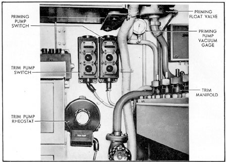
Figure 2-2. Trim pump controls.
room. However, the motor is started or
stopped by push-button controls in the control room. Once started by these controls, the
speed of the pump, and thereby the rate at
which water is moved in the system, is regulated by a rheostat control also located in the
control room just below the push-button
switches (see Figure 2-2). Although the trim
pump is driven by an electric motor, the
starting of the motor does not guarantee that
the trim pump will pump water, for since the
trim pump is of the centrifugal type, it cannot
pump air. Therefore, it cannot be operated
until the system is free of air.
2B2. Priming pump. Freeing the system of
air is the function of the priming pump, located outboard of the trim pump. Since any
appreciable amount of air entering the inlet
side of the trim pump will cause it to lose
suction and thereafter run without pumping,
it is necessary to use the priming pump to
eliminate the air. A vacuum gage, mounted
in the control room, provides a check on the
satisfactory operation of the priming pump.
If the trim pump is started and there is no indication of flow, the priming pump should be
started at once to insure that the trim pump
is fully primed, before other sources of
trouble are investigated.
The priming pump, like the trim pump,
is started or stopped by push-button controls
in the control room. The priming pump is a
vacuum pump with a float valve in the line
running from the priming pump to the trim
manifold and the trim casing. The valve consists of a float with a ball-ended stem. The
purpose of the float is to permit the passage
of air and to prevent the passage of sea water
into the priming pump. As the water rises in
the float valve, the upper part of the ball-ended stem is automatically forced against the
valve seat, thus preventing sea water from entering the priming pump. When the float
valve is filled with water, the vacuum gage
6
will read about 20 inches of vacuum and the
system is fully primed.
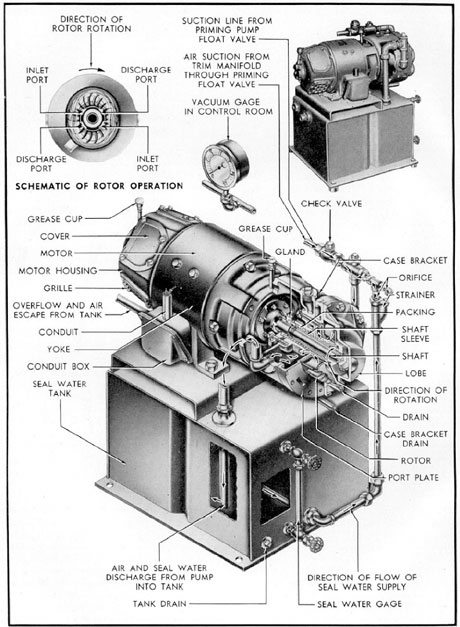
The priming pump is of the water-piston
type and consists of three major parts
1) rotor, 2) lobe, and 3) port plate. The rotor
is made up of a series of curved plates projecting radially from the hub. The lobe is
elliptical in shape and forms the outer casing
for the rotor. The port plate consists of-two
inlet and two outlet ports corresponding to
the inlet and outlet ports on the rotor. The
pump is end-mounted on the direct driving
electric motor as shown in Figure 2-3.
Before starting the priming pump, it is
necessary first to provide sealing fresh water
to it. This water is needed to fill the lobe partially and provide a water seal. Fresh water
should be added until the seal water gage
shows 2/3 full (see Figure 2-3). Serious damage may result if the pump is allowed to run
in a dry condition. The motor is then started
by the push-button control in the control
room.
In operation, the rotor revolves in the
lobe, which has been partially filled with
water, at a speed high enough to throw the
water out from the hub by centrifugal force.
This results in a solid elliptical-shaped ring
of water revolving at the same speed as the
rotor. Referring to Figure 2-3, it will be seen
that a ring of water for a given rotor section,
guided by the lobe, will move in and out
from the hub, forming a liquid piston. As the
rotor passes the inlet port, the water ring
is farthest from the hub and air is permitted
to enter. As the rotor advances to the discharge port, the air space becomes less and
air is forced out the discharge port. This
cycle is repeated twice for each revolution of
the rotor.
2B3. Operation of the trim pump. A brief review of the general principles of the centrifugal pump will be helpful in understanding
the operation of the trim pump. A centrifugal
pump, as the name implies, employs centrifugal force to move a liquid from a lower to a
higher level. In its simplest form, this type
of pump consists of an impeller rotating in a
watertight casing which is provided with inlet
and outlet ports.
The impeller consists of two parallel
disks with curved vanes, or bulkheads, radiating from the hub and between the disks.
One of these disks (upper or lower, depending
upon where the water is brought in) has an
inlet port, or circular opening, called the eye,
which is concentric with the hub of the impeller. Actually then, one disk holds the
impeller to the shaft while the other admits
the water. The periphery of the impeller is
open, as shown in Figure 2-1.
In operation, water enters the eye of the
impeller, is picked up by the vanes and accelerated to a high velocity by the rotation
of the impeller, and then discharged by centrifugal force into the casing and out the
discharge port. When water is forced away
from the eye of the impeller, pressure in this
area is lowered ("suction" is created), and
more water flows in. Consequently there is a
constant flow of water through the pump.
Considerable air in the inlet port of the pump
will interrupt the action of the pump since,
upon entering the impeller, it will break the
suction which is dependent on the presence
of water at the eye. For this reason, the pump
casing and the system served by the pump
must be completely filled with water before
starting to pump.
The centrifugal pump just described has
only one impeller and is known as a single-stage pump. A pump with four impellers may
be known as a four-stage pump; with six impellers, a six-stage pump; and so forth. In
actual practice, however, any pump with more
than one stage is referred to as a multi-stage
pump.
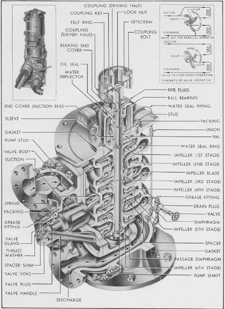
The mechanical details of the trim pump
are shown in Figure 2-1. It will be seen that
the pump is a six-stage centrifugal pump.
The valve on the forward end permits either
parallel or series operation and is manually
operated. The schematic diagram in the upper
right corner of the illustration shows the flow
of the water being pumped, for both series
and parallel operation. With the manually
operated series-parallel valve in the SERIES
position, the incoming water enters the first
stage, proceeds through the second and third
stages, and then back through the series-
7
Figure 2-3. Priming pump.
8
parallel valve to the fourth, fifth, and sixth
stages. With the series-parallel valve in the
PARALLEL position, half of the inlet water
proceeds through the first, second, and third
stages, and is then discharged through the
series-parallel valve. Simultaneously, the other
half of the inlet water is directed by the
series-parallel valve to the fourth, fifth, and
sixth stages, and is then discharged directly.
Series operation of the pump produces twice
the discharge pressure, but only half the
volume produced by parallel operation. The
pump is operated in series only when the submarine is at a depth of approximately 250 feet
or more and discharging to the sea; the higher
pressure is necessary to overcome the greater
sea pressure encountered at that depth.
In summary, it must be remembered that
before starting the trim pump after installation or reassembly, it is necessary to make
certain that the trim system lines and the
pump casing are free of air. After the trim
pump has been used, the casing should remain
primed, because of the location of the pump
in relation to the trim manifold. But if flow
does not commence after starting the trim
pump, the priming pump should be used to
eliminate the air before restarting the trim
pump.
The trim pump should not be operated
at speeds greater than are necessary to produce the rate of flow specified for a given
depth.
The following table lists the proper valve
position and pump output in pounds of water
per minute, recommended for different depths.
Depth
Pump Output
Valve Position
On surface
1500-2500 lbs. per min.
Parallel
0-200 ft.
1500 lbs. per min.
Parallel
Trimming- tank to tank
1500 lbs. per min.
Parallel
200-250 ft.
1250 lbs. per min.
Parallel
250-400 ft.
1000 lbs. per min.
Series
400 ft. or more
1000 lbs. per min.
Series
The pump should not be operated at a
motor speed greater than 2400 revolutions per
minute. Excess speeds place an overload on
the bearing and mechanical parts of the pump
and motor and may cause breakdown.
C. MANIFOLDS
2C1. Trim manifold. In Section 2A, the trim
manifold is referred to as the center of distribution for the trim system. It acts as a switchboard between the trim pump and the lines
of the system, providing a centralized station
to direct the flow of water to and from the
variable tanks. Used in connection with the
trim manifold, but connected to each variable
tank, is a measuring gage, or liquidometer.
These gages record the amount of water in
each tank and provide the diving officer with
an indication of the amount of water ballast
being redistributed by the trim manifold
through the trim system. The trim manifold
is mounted hip-high on the port side of the
control room just forward of the after bulkhead. The gage board is mounted directly
above it.
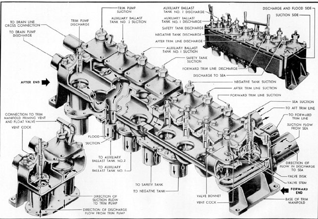
Figure 2-4 shows the mechanical construction of the trim manifold, with the proper
nomenclature of its parts, as used in this
manual. The manifold is a boxlike, two-piece
casting, divided internally into two longitudinal compartments known respectively as
the suction and discharge sides. The suction
side contains eight suction control valves,
while the discharge side has eight discharge,
or flood, control valves. Each of these sixteen
valves is of the disk and seat type, with rising stems and individual bolted-on bonnets.
Name plates, attached to each bonnet, indicate
the function of that particular valve.
Starting from the after end outboard of
the manifold, the valves control the functions
indicated in the table on page 11.
The discharge valves are all on the starboard side of the manifold, with the corresponding suction valves opposite them on
the port side. A special wrench for operating
the valves is provided.
Flanged outlets are cast integral with the
manifold to connect with the lines of the
9
Figure 2-4. Trim manifold.
10
Outboard-Suction
Inboard-Discharge
1. Trim pump suction
9. Trim pump discharge
2. Auxiliary ballast tank No. 2 suction
10. Auxiliary ballast tank No. 2 discharge
3. Auxiliary ballast tank No. 1 suction
11. Auxiliary ballast tank No. 1 discharge
4.Safety tank suction
12. Safety tank discharge
5.Negative tank suction
13. Negative tank discharge
6. After trim line suction
14. After trim line discharge
7. Forward trim line suction
15. Forward trim line discharge
8. Sea suction
16. Discharge to sea
system. Two outlets on the after end lead to the
drain line cross connection and to the drain
pump discharge, to permit emergency use of
the drain pump for actuating the trim system.
In all pumping operations, the trim pump
suction and the trim pump discharge valves
on the manifold must be opened to permit
flaw within the system. To flood a tank, the
discharge valve for that tank must be opened
at the trim manifold; to pump a tank, its suction valve must be opened. This should be
done before the trim pump is started. All
valves on the manifold should be shut immediately after the pumping operation is complete.
Figure 2-4 shows the direction of flow when
flooding or pumping auxiliary ballast tank
No. 2.
Fully detailed instructions for specific
trimming operations are given in Chapter 4.
They explain the exact procedure to be followed in operating the trim manifold in conjunction with the other units of the trim
system.
2C2. Forward and after WRT and trim tank
manifold. The WRT and trim tank manifolds
are used in conjunction with the trim manifold to control the flooding and pumping of
the WRT tanks and the trim tanks, both fore
and aft.
The forward trim manifold (Figure 2-5)
is located in the forward torpedo room, port
side, aft of the torpedo tubes. The after trim
manifold is located in the after torpedo room,
port side, forward of the torpedo tubes (see
Figure 3-9).
The forward and the after WRT and trim
tank manifolds are identical in operation and
construction, differing only in the fact that
they serve different tanks.
The body of each trim manifold is a two-chambered casting containing two valves
which control flood and suction of the WRT
tank and the trim tank, respectively. The after
valve in the after torpedo room and the forward valve in the forward torpedo room control the trim tank. The valves are of the disk
and seat type with bolted bonnets. The connecting passage between chambers of the integrally cast valve casting allows either valve
to be operated independently. The handwheels carry name plates designating the uses
of the individual valves.
When open, the manifold valve marked
TRIM TANK FLOOD AND SUCTION permits the flooding or pumping of the trim tank
from, or into, the trim system when the trim
line is on service.
The other valve, marked WRT TANK
FLOOD AND SUCTION, permits the flooding or pumping of the WRT tank from, or
into, the trim system when the torpedo tube
drain stop valve to the WRT tank is open.
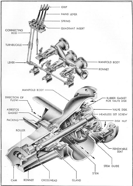
2C3. Torpedo tube drain manifold. In Section 2A the flooding and draining of the
torpedo tubes were mentioned as one of the
functions of the trim system. This function
is controlled by the torpedo tube drain manifolds. Two of these manifolds are located in
the forward torpedo room, each servicing
three torpedo tubes; two are located in the
after torpedo room, each servicing two torpedo tubes. Figure 3-9 shows the location of
these manifolds (the forward manifold servicing the three starboard tubes is not shown
in the illustration). In each case, the control
levers are adjacent to the manifold.
The body of the torpedo tube drain manifold is a three-chambered casting, housing
three cam-actuated plunger-type valves, and
provided with flanged outlets for connection
to the trim system and to the torpedo tube
11
Figure 2-5. Forward WRT and trim tank manifold.
12
Figure 2-6. Torpedo tube drain manifold.
13
drains. The cam mechanisms are attached to
the back of the casting. Separate control
levers and connections are provided for each
of the valves (see Figure 2-6).
Each hand lever operates one cam, through
the action of its connecting rod and cam lever.
In Figure 2-6 the cam and valve are shown in
the open position, permitting water to flow to
or from the torpedo tube drains. In draining
or flooding the tubes, the manifold valves are
used in conjunction with the torpedo tube
drain stop valve to the WRT tank, which
must be open when draining from the tubes
to that tank.
D. VALVES
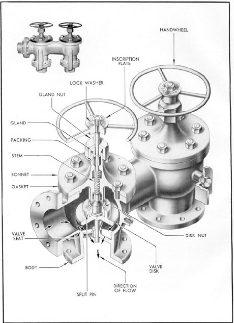
2D1. Trim pump sea stop valve. In discharging water ballast from any part of the trim
system to sea, the trim pump sea stop valve
must be opened, thus providing a passage
from the trim manifold through the pressure
and outer hulls to the sea. The same line is
used to permit water to enter the system from
the sea when additional water ballast is to be
added. This valve is located on the port side
of the control room, directly below the trim
manifold (see Figure 3-9).
The sea stop valve is of the rising stern
disk and seat type, with a bolted bonnet.
Flanged connections are provided to the sea
discharge line, the trim manifold, and the
magazine flood line. A guide which extends
below the valve disk serves to center and seat
the valve disk. The mechanical construction
is shown in Figure 2-7.
The connection to the pressure hull is a
flange, cast integral with the valve body below
the valve seat to insure a pressure-tight connection to the pressure hull. The lower part
of the valve body, with the screwed flange,
projects through the pressure hull and connects to the line overboard.
Turning the handwheel counterclockwise
to the OPEN position raises the, valve disk
and permits the suction of sea water into the
trim system, the direct flooding of the magazine, or the overboard discharge of water
from the trim system.
Turning the handwheel clockwise seats
the valve disk and cuts off the suction from,
or discharge to, the sea. In Figure 2-7 it will
be seen that the handwheel controls only the
up-and-down movement of the stem; therefore, only the suction from, or discharge to,
sea is affected by this handwheel. The side
outlets remain open irrespective of the valve
stem position, thereby providing a means of
supplying water to flood the magazine and the
trim system simultaneously.
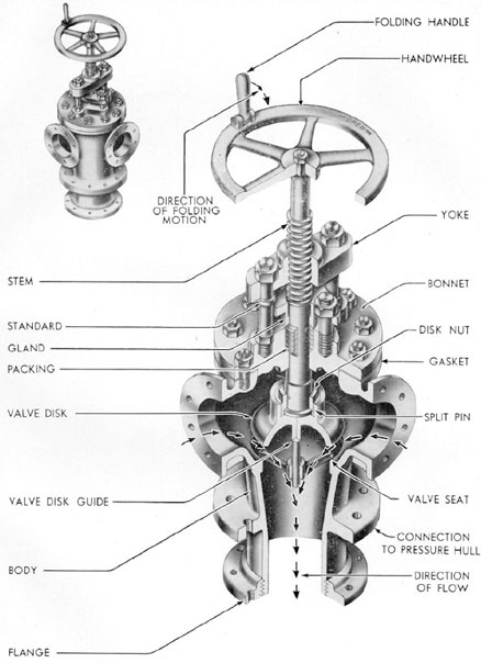
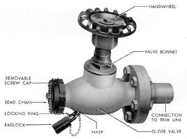
2D2. Torpedo tube drain stop valve to the
WRT tank. The torpedo tube drain stop valve
to the WRT tank serves as a stop valve between that tank and the individual torpedo
tube drain valves.
There is a torpedo tube drain stop valve
to the WRT tank in both the forward and the
after torpedo rooms (see Figure 3-9). Both of
these valves are identical in function and construction (see Figure 2-8).
The torpedo tube drain stop valve to the
WRT tank is a globe-type valve with a bolted
yoke-type bonnet and a rising stem. The
mechanical construction is shown in Figure
2-8. The inscription plate carries the valve
designation. In the OPEN position, the valve
permits water to be blown into the torpedo
tubes from the WRT tank, or to be drained
back into the tank from the torpedo tubes,
provided the individual torpedo tube drain
valves are open. The valve is also opened to
flood or drain the WRT tank by the trim line.
All flow of water to and from that tank is cut
off by closing the valve.
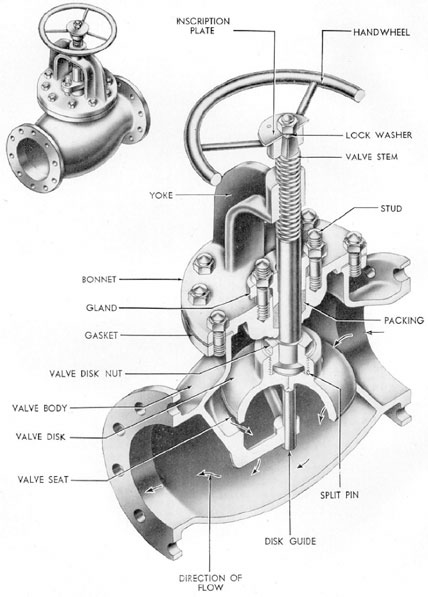
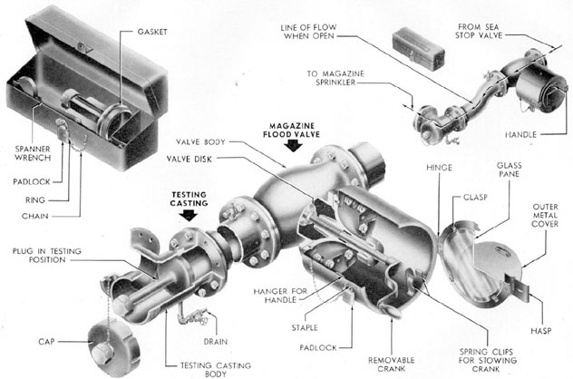
2D3. Magazine flood valve and testing casting. The magazine flood valve and testing
casting (see Figure 2-9) provide an emergency
method of flooding the magazine compartment. This is another secondary function of
the trim system.
The magazine flood valve is used to control this emergency flooding system. The
testing casting is used in checking the magazine flood valve to make certain that it is
ready for immediate use. Both the magazine
flood valve and the testing casting are located
in the control room on the magazine flood line
14
Figure 2-7. Trim pump sea stop valve.
15
Figure 2-8. Torpedo tube drain stop valve to WRT tank.
16
Figure 2-9. Magazine flood valve and testing casting.
17
of the trim system. The accessory box containing the operating plug and wrench is
mounted directly above the testing casting.
The magazine flood valve is a disk and
seat type globe stop valve with a bolted bonnet, rising stem, and flanges for connection
to the testing casting and the sea stop valve.
A cylindrical box bolted to the bonnet encloses the stem. The end of the protecting
box has a hinged glass door equipped with a
hasp-and-chain padlock. Protecting the glass
cover, is a smaller, hinged metal cover. Inside
the box is a crank that fits the valve stem.
The magazine flood valve is used only in
emergency to flood the magazine compartment. The outer metal cover and the glass
door are unlocked and opened during periods
of possible emergency or when testing. In
cases of emergency, the glass door should be
broken. The valve is opened, using the crank,
to flood the magazine.
The testing casting is used for periodic
testing of the magazine flood valve to make
certain that the flood valve is in operating
condition and ready for use when needed.
The testing casting is T-shaped, with the
long leg and one arm flanged for connection
to the magazine flood line and the flood valve.
The other arm is threaded to receive the protecting cap. The operating plug, in the accessory box, fits the inside threads in the testing
casting. The wrench fits the cap and the plug.
In testing the magazine flood valve, the
cap is removed from the testing casting and
the plug is screwed in tightly. After the valve
is opened, the vent in the magazine line is
opened to see if the line contains water. If the
valve is operating correctly, the line will contain water. The flood valve is closed and the
line through the testing casting drain is
drained before the plug is removed. Next, the
plug is removed and the cap replaced, making
Figure 2-10. Trim line hose connection.
18
the testing connection watertight. The plug
and wrench are then replaced in the box, and
the door to the valve stem enclosure is locked.
2D4. Trim line hose connection. The trim
line hose connections (Figure 2-10) may be
used as fire main outlets or as additional bilge
suction. They may be used in pumping a compartment, or any area not covered by the drain
system, when there is suction in the trim
lines.
The forward trim line has three hose connections; one in the forward torpedo room,
one in the forward battery compartment, and
one in the control room. The after trim line
has five hose connections: one each in the
after battery compartment, the forward engine room, the after engine room, the maneuvering room, and the after torpedo room.
The hose connection is a globe valve with
a rising stem. It has one end flanged for connection to the trim line and the other end
threaded for a hose coupling. A locking cap
attached to the valve body by a chain, and
secured with a padlock, fits onto the hose
coupling end.
In using the hose connection either for
flooding or pumping, the cover is unlocked
and removed. The hose is attached by coupling to the threaded end of the connection.
The valve is opened by turning the handwheel
counterclockwise, thus providing suction or
flooding as required. When sufficient water
has been obtained or removed, the valve is
shut, the hose removed, and the cover replaced
and locked. When not in use, the valve should
be kept shut and the cover locked to prevent
possible leakage.