14A1. The air-conditioning cycle. The Freon
12 refrigerant cycle in the air-conditioning
system is the same as that in the refrigeration system. In general, the mechanical circuit of equipment is also similar; the main
difference is that the air is brought by forced
ventilation through ducts to the evaporators
and returned through ducts to the rooms.
14A2. The air-conditioning plant. The air
conditioning plant consists of the following
main elements:
1. Two compressors, York-Navy Freon 12,
enclosed single-acting vertical, two cylinders
4-inch bore x 4-inch stroke, rated at 4 refrigeration tons each.
2. Two condensers, York-Navy Freon 12,
horizontal shell-and-tube 4-pass type.
3. Two receivers, York-Navy Freon 12
type.
4. Four evaporators, with finned cooling
coils in two casings.
5. Two conning tower evaporators, in one
casing.
14A3. Double system arrangement. The
main elements are connected as two separate
systems, each containing all necessary valves,
gages, and controls for automatic operation.
The cooling coils of these two systems, how
ever, are placed side by side in an evaporator
casing and, though appearing to be a single
unit of coils, are nevertheless entirely separate. Thus either of the two systems may
be operated alone, with its cooling action taking place in the evaporator casing. There are
two such casings, located in different rooms
in the submarine. Figure 14-1 (inserted at the
back of the book) shows the complete system,
with all piping connections and the location
of all elements, valves, and devices. This diagram illustrates clearly the double arrangement. A separate diagram shows the ducts
and air distribution system, which are described later.
14A4. Interconnection of double system.
The two systems, while ordinarily set to operate individually, are interconnected. On the
200 class submarines, the interconnecting
pipes run between 1) the discharge lines of
the compressors; 2) the outlet lines of the
condensers; 3) the inlet or suction lines to
the compressors. Shutoff valves in these interconnecting, pipes permit any of the main
elements to be cut out of one system and put
into the other, in case of necessity.
Figure 14-1 shows these interconnecting
pipes and valves clearly; they are left uncolored in the diagram for the sake of clarity.
The colored piping indicates the circuits in
which an actual flow of refrigerant is taking
place during normal operation. There is no
flow in the interconnecting pipes unless their
shutoff valves are opened; normally they are
closed. On the 300 class submarines, the inter
connecting pipes run between 1) the discharge lines of the compressors, and 2) the
outlet lines of the condensers. There is no
interconnection between the suction lines of
the compressors.
14A5. The capacity of the air-conditioning
system. The capacity of the system is 8.0
refrigeration tons with the two compressors
operating at 330 rpm; and 6.4 refrigeration
tons with the two compressors operating at
265 rpm; 10 gallons per minute of 85 degrees F
water per refrigeration ton are circulated
through condensers; and suction pressure
corresponds to an evaporation temperature
of 35 degrees F.
Since most of the mechanical parts are the
same as those in the refrigerating system,
only the different parts are described.
B. THE COMPRESSORS
14B1. General description. Each of the two
compressors is quite similar to the refrigeration system
compressor. No separate illustration of them is given, since the main difference
100
lies only in the size, which is as follows:
1. Bore, 4 inches; stroke, 4 inches.
2. Drive, by 5 V-belts from a two-speed
4.9- to 4.1-hp electric motor, 250 (175-345)
volts direct current (d.c.).
3. Lubricating oil charge, 10 pints of Navy
Contract Oil, Symbol No. 2135, or equivalent.
14B2. Suction and discharge valves. Attention is called to the fact that in the 4 x 4 air
conditioning compressor, the valve diaphragms or disks are exactly alike in both
valves, and hence are interchangeable when
new. Each valve has three disks, slightly
dished and assembled in the following order;
bottom disk, concave downward, small spacer;
middle disk, concave upward; top disk, concave downward. The disks are 3 3/4 inches in
diameter and contain three concentric circles
of 5/32-inch holes, that must be aligned in
assembly.
It is not good practice to permit a Freon
12 compressor to remain idle for an extended
period of time. Compressors should be operated at least once a week. Therefore, if duplicate or standby compressors are furnished,
they should be operated alternately, changing from one to the other at least every week.
C. THERMOSTATIC EXPANSION VALVE
14C1. The thermostatic expansion valve.
Two types of this valve are in use, one for
refrigerating, called the internal equalizer;
and the other for air-conditioning, called the
external equalizer. A general description is
given first, then a detailed description of each
type.
The remote bulb assembly (sometimes
called the power assembly) contains Freon 12,
and is attached to the suction line at the exit
of the evaporator coil. Since Freon 12 has an
exact temperature-pressure relationship, any
variation in temperature of the suction line
at the point of attachment produces a corresponding variation of pressure within the
bulb. This pressure is communicated to the
upper side of the diaphragm in the expansion
valve. The lower side of the diaphragm (with
airtight separation from the upper) is part of
the regular refrigeration fluid circuit. Therefore any pressure difference between both
sides causes the diaphragm to move. This, in
turn, moves the valve stem, permitting more
or less liquid Freon 12 to flow through.
The thermostatic expansion valve controls
the quantity of liquid refrigerant that is admitted to the evaporator according to changes
in the superheat of the suction vapor leaving
the evaporator.
This valve is designed to maintain a constant degree of superheat in the refrigerant
vapor leaving the cooling coils, regardless of
suction pressure. Thus its function is two
fold:
1. Automatic expansion control.
2. Prevention of liquid refrigerant from
surging through the evaporator to the compressor. It acts also to disperse the liquid
Freon 12 in small droplets for easier and
quicker evaporation and divides the high- and
low-pressure sides of the system at this point.
The piping connections include a liquid
strainer and a solenoid valve, with shutoff
valves for servicing the strainer, solenoid
valve, or thermostatic expansion valves; also
manually operated valves and bypass for use
in case it is desired to examine the thermostatic expansion valves, solenoid valve, or to
clean the strainer.
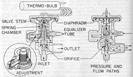
14C2. Internal equalizer. This type of expansion valve is illustrated in Figure 7-10.
After the liquid Freon 12 enters the valve
and passes through the orifice, it is at low-pressure level of the evaporator. A port, or
channel, bored through the valve seat retainer makes the spring chamber a part of the
low-pressure line. The low-pressure refrigerant entering the spring chamber adds its
pressure to the pressure of the spring on the
diaphragm. Opposing this combined internal
pressure is the pressure from the remote bulb
on the other side of the diaphragm.
14C3. External equalizer. An expansion
valve is installed at the entrance of the evaporator tubing, and its bulb is attached at the
exit of the evaporator tubing. Theoretically,
the pressure inside the evaporator should be
101
constant. Any loss of pressure between the
two ends of the evaporator coil would be of
great importance as far as the proper working
of the expansion valve is concerned.
In a refrigeration system, the evaporator
tubing is usually of fair-sized diameter. Any
pressure drop therein would be negligible.
But in an air-conditioning system, the evaporator tubing is likely to be of smaller diameter, with restricted return bends. More
over, the tubing is arranged in several separate banks joined by distributor headers from
the single entrance pipe coming from the
receiver. Such conditions cause a sizable
pressure drop between the two ends of the
evaporator, which, if not corrected, produce
a material increase in the superheat of the
vapor.
The external equalizer is designed to offset
this undesired condition. Figure 14-2 illustrates the external equalizer type of expansion valve. In this type, the port in the seat
retainer is eliminated. Instead, there is an
opening through the wall of the valve directly into the spring chamber. Fastened to this
opening is a small diameter tubing, the other
end of which communicates with the evaporator
coil just beyond the point of greatest
pressure drop. This point is usually just beyond the distributor header at the entrance
end of the evaporator, because most of the
drop occurs across this small region. With
this supplementary connection, the pressure
on the underside of the valve diaphragm approximates the mean evaporator pressure.
The pressure drop across the distributor
header still exists, of course, but its effect on
the valve diaphragm has been balanced out,
so that the superheat is back to normal, and
the capacity of the system is not decreased.
14C4. Adjusting the thermostatic expansion
valve. Navy specifications call for 10 degrees of
superheat and this setting is usually made at
the factory. If it becomes necessary to adjust
the superheat setting, remove the seal nut
and manipulate the adjusting stem. Turning
this stem clockwise (tightening the spring)
increases the superheat and reduces the flow
through the valve. Conversely, turning the
stem counterclockwise reduces the superheat
and increases the flow of liquid through the
valve. Once set, it is seldom necessary to
readjust.
14C5. Thermostatic expansion valve trouble.
The thermostatic expansion valve should
function without any difficulty if the system
is free of dirt or foreign matter and contains
no moisture. Presence of dirt or foreign matter between the seat and the valve prevents
it from closing tight. Likewise, the presence
of moisture in the system causes a freeze-up
at the valve port and blocks the passage of
Freon 12.
The system does not operate satisfactorily
unless there is at least a 60-psi differential in
pressure, between the high-pressure and low-pressure sides of the valve.
If it is evident that no Freon 12 is passing
through the expansion valve, the valve should
be disassembled, after closing the proper cut
out valves, by removing the capscrews connecting the power assembly to the body. This
permits the valve cage assembly to be examined for the presence of frost, ice, or dirt.
Due caution should be taken in reassembling the thermostatic expansion valve to see
that all gaskets are properly placed, and that
the valve cage assembly is properly aligned.
Gaskets must be of the prescribed material.
It should be noted that these valves are delicate instruments and do not withstand rough
usage. They should be handled with care.
D. SUCTION PRESSURE REGULATING VALVE
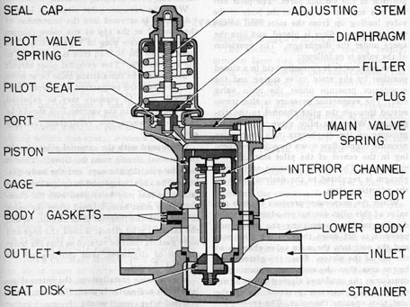
14D1. Purpose. The suction pressure regulating valve (see Figure 14-3), used only in
the air-conditioning system, is a constant
pressure device. Four of these were formerly
used in the complete system, there being one
installed in the suction line from each bank
of the air-conditioning evaporators. On the
300 class submarines, only one of these valves
is now used, and it is located in the pump
room, on the suction line of the No. 1
Figure 14-3. Suction pressure regulating valve.
103
air-conditioning unit. Normally this valve is by
passed and is cut into the system only during
the time that the No. 1 air-conditioning unit
is cross-connected to the refrigerating system.
By having a suction pressure regulating
valve installed in the suction line of the No. 1
air-conditioning unit, it is possible to operate the refrigerating system, with a suction
pressure of about 5 pounds, and at the same
time, to operate the No. 1 air-conditioning
system, with a suction pressure of 35 pounds.
The suction pressure regulating valve
serves the purpose of maintaining a substantially constant vaporizing temperature in the
evaporator coil to which it is connected, regardless of the temperature prevailing in the
suction line itself, or of sudden load changes
or suction pressure fluctuations.
14D2. Operation. The type of constant
pressure valve used is known as a pilot-operated piston valve. Figure 14-3 shows the disposition of the various parts. The pilot circuit is a separate channel in the body of the
valve leading up from the inlet side, across
the top where a filter is placed, and into the
space under the diaphragm. The operation
of the valve is as follows:
The main valve is normally held in a closed
position by the main valve spring and the
evaporator pressure under the main valve
seat. The evaporator pressure is also transmitted through the pilot channel to the diaphragm. When the pilot valve is closed by
pressure of the diaphragm, this evaporator
pressure cannot flow down through the opening in the center of the pilot seat into the
main valve. The closing pressure on the diaphragm is regulated to the desired value by
the adjusting stem.
When the evaporator pressure exceeds the
value of this pilot diaphragm adjustment, the
diaphragm lifts, permitting the evaporator
pressure to act down through the pilot seat,
and the port into the main valve chamber to
the top of the piston. Since the piston is of
larger area than the main valve opening, it
overcomes the combined closing forces of the
spring and evaporator pressure under the
seat, thus opening the valve. The reverse action takes place
when the evaporator pressure
falls below the setting of the pilot adjustment.
However, in actual operation, this action
does not take place in complete steps of
opening and closing. Normally, the piston
assumes an intermediate floating position,
responding to fluctuations in the evaporator
pressure; these fluctuations are balanced out
and the resulting pressure is maintained at a
substantially constant value asset by the adjusting stem. Since Freon 12 has a strict
pressure-temperature relationship, this automatic action maintains the temperature within the evaporator coil at a nearly constant
level.
14D3. Internal and external pilot circuits.
The suction pressure regulating valve may be
used with either an internal or external pilot
circuit. As an internal pilot circuit, it is used
as described, with the evaporator pressure
coming through the internal channel in the
valve body, and the plug inserted.
With the external pilot circuit, a 3/8-inch
o.d. tubing is screwed into the connection of
the channel at the top of the valve (shown
closed by a screw plug in Figure 14-3). The
other end of the 3/8-inch tube is connected to
the suction line. This external pilot circuit
is used when the installation must be at some
distance from the evaporator, or where a considerable drop in pressure may be expected.
The connection in the suction line should be
at a point where low refrigerant velocity
exists.
When used with the external pilot circuit,
the internal circuit must be closed. This is
done by rotating the cage and the body gaskets. The cage flange and body gaskets contain holes that may be aligned with the channel. They must be so aligned when the valve
is used with the internal pilot circuit. When
the external pilot circuit is used, the cage and
body gaskets must be rotated so that the holes
are out of alignment, thus shutting off the
internal channel.
In submarine installations, the internal pilot circuit ordinarily is used. However, if the
external pilot circuit would give much better
104
operation of the system, the external tubing
is easily attached.
14D4. Adjustment. The suction pressure
regulating valve is designed to operate properly at light loads. A minimum differential
of 2 pounds between evaporator and suction
pressures is sufficient for proper operation.
The pressure adjustment range runs from
2 psi to 70 psi. Rotating the adjusting stem
clockwise gives a higher pressure setting, and
vice versa. One complete turn of the adjusting stem changes the setting by approximately 4 pounds.
When adjusting, insert a pressure gage in
the external pilot tube connection, first removing the plug or tubing. Be sure to allow
ample time for the system to stabilize itself
between adjustments. If the valve fails to
respond to an adjustment, check the suction
pressure to make sure that the compressor is
actually capable of producing a pressure
lower than that desired in the evaporator, remembering
that a 2-pound differential is sufficient.
Be sure to replace the seal cap after
adjustment.
14D5. Cleaning. All service operations may
be performed on this valve without removing
it from the line. The pilot channel filter may
be removed for cleaning, using a screwdriver.
The entire pilot valve housing may be removed by using an ordinary wrench on the
hexagon at the top. The diaphragm and pilot
seat may be cleaned, if necessary, with a soft,
clean cloth.
The main upper body is removed by taking
out the four capscrews. Note that the piston
has a loose fit and slides freely in the housing; be careful that it does not drop. The
cage and inlet strainer may now be lifted out
for cleaning.
In reassembling, be sure to replace all gaskets. Be sure that the holes in the cage flange
and body gaskets are properly placed, in line
with the channel for the internal pilot circuit,
and out of line for the external pilot circuit.
E. THE EVAPORATOR
14E1. Construction. The air-conditioning
evaporator is constructed to provide a large
cooling and condensing surface in a small
space. The overall dimensions are, roughly
forward coils, 5 feet 7 inches long, 11 inches
high, 9 inches wide. The after coils are of
shorter length, about 3 feet 6 inches, but of
the same height and width as the forward
coils. These coils are part of the Freon 12
piping within this space. Around the coils is
the evaporator casing into which the inlet
and outlet air ducts are connected.
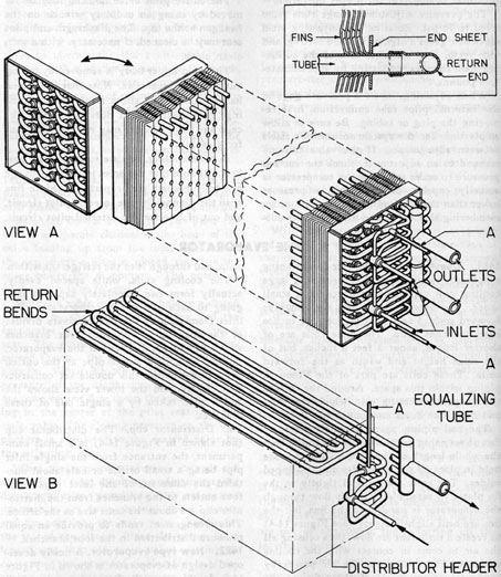
The coil piping passes through plates or
fins of very thin metal, stacked six to the inch
the whole length of the coils. These fins are
held in place by small dimples and tin-tipped
solder. The coils are wedged tightly to the
fin plates in assembly. The air flow through
the evaporator is parallel to the fins, but the
fins are bent slightly zigzag (see Figure 14-4)
to create a turbulent air flow, thus causing all
the air to come in contact with the cooling
surfaces. The heat, from the air passes by
conduction through all of these fins to the
cooling coils proper or banked refrigerant
main, and through it to the refrigerant within.
The cooling coils, while spaced evenly,
actually form two completely separate sets,
going to each of the two compressors. The
inlet from each of the two receivers divides
at the distributor cup into four branches
which run in parallel within the evaporator,
joining back to a single pipe at the outlet.
Figure 14-4 shows this double set construction clearly, and the lower view shows the
coiled path taken by a single one of these
branches.
a. Distributor cup. The distributor cup
(not shown in Figure 14-4) is a small compartment, the entrance from the single inlet
pipe being a small orifice or hole about one
third the diameter of the inlet pipe. The
four outlets to the branches from the distributor cup are about the same size as the orifice.
This arrangement tends to provide an equal
pressure distribution in the four branches.
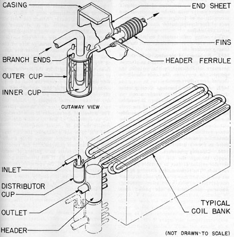
14E2. New type evaporator. A newly developed design of evaporator is shown in Figure
14-5. In this type, the fins are separate small
disks around the piping, instead of single
105
plates across the whole evaporator. This construction permits quicker and better cleaning.
There is also a new type of distributor cup,
an inner cup, that overflows and fills the outer cup, and goes out into the branches, the
ends of which project down into the cup.
These ends have small holes at the top of the
cup and are open at the lower extremity (see
enlarged view in Figure 14-5).
The reason for this new design of cup is
that while theoretically there should be no
throttling action or expansion of liquid into
Figure 14-4. Air-conditioning evaporator.
106
flashgas while flowing into a cup, practically,
there usually is some. The holes into the
branch ends at the top of the cup permit any
such flashgas to be distributed equally into
the four branches. This design also has a low-pressure drop across the distributor header.
In installation, these cups should be set upright and not turned on their sides, which
would cause gas binding, and some of the
branches would lack their proper share of
liquid.
14E3. Conning tower evaporators. Two
evaporators, contained in a single casing, are
located in the conning tower. They are connected to the liquid and suction lines of No. 1
and No. 2 air-conditioning plants, respectively. Each evaporator has its own expansion
valve and solenoid valve; however, there is no
thermostat. The solenoid valve is controlled
by a hand-operated switch and can be operated manually only.
The installation and design of conning
Figure 14-5. Air-conditioning evaporator, new type.
107
tower air-conditioning units vary with each
class of vessel. Therefore, no detailed
description can be given to cover each installation.
F. CLEANING THE EVAPORATOR
14F1. Maintenance and cleaning of cooling
coils. An accumulation of dust or organic
material on the surfaces of a cooling coil decreases the quantity of heat that can be transferred, and lowers the operating efficiency of
the coil. Even a thin film on the surface reduces the capacity to an undesirable extent.
This is particularly applicable to cooling
coils since the condensation of atmospheric
moisture on the coils tends to accelerate the
accumulation of foreign matter. The presence of this foreign matter also tends to restrict the air flow.
The cooling coils installed on submarines
should be cleaned in accordance with the following instructions.
14F2. Frequency of cleaning. Coils should
be inspected monthly and cleaned as often as
necessary, as indicated by the periodic inspection. In any case, the coils should be
cleaned every three months.
14F3. Access for cleaning. Cooling coils
should be provided with ready access to
facilitate inspection and cleaning. If possible,
a section of ducts on either side of the coils
should be portable. If this is not possible,
the bottom of the ducts on both sides of the
coil should be readily removable. In cases
where such access does not already exist, it
should be provided by the ship's' force or
listed as a work item for the next overhaul.
14F4. Cleaning procedure. Shut off the air
supply through the coil and remove the
portable section of duct or portable plate on
each side. The recommended cleaning agents
are nontoxic and may be safely used in closed
compartments with ventilation operating,
whenever conditions do not permit open
doors and hatches in the compartment.
When cleaning the cooling coils, do not
shut off the compressors as cleaning agent
RM 70 is volatile.
Prepare a bucket of RM 70 solution, a nontoxic solvent, in warm water (about 110 degrees F)
in the ratio of 4 ounces of RM 70 to 1 gallon
of water.
Provide a spray lance or paint gun with a
piece of hose sufficiently long to reach conveniently into a bucket. Attach the inlet air
connection to a source of air at about 60
pounds. Bleed the air so that a fine spray is
produced. Wet down the entire coil surface,
working from the air discharge side of the
coil, and allow to stand for about five minutes. Readjust the gun to produce a spray
of high velocity, and wash the coils with
clean water, blowing from the air discharge
to the air inlet side. If found necessary, provide some means to prevent the blast of dirty
solution from carrying past the coil and up
the supply duct. Drain off and wipe away
any of the solution remaining. Allow the
coils to dry and replace the access plates.
The Bureau of Aeronautics is now developing an equivalent of RM 70 which does not
require the use of critical materials.
If RM 70 is not procurable, the coil may
be cleaned in a similar manner using a solution of trisodium phosphate, in the ratio of
1/2 pound of crystals to 3 gallons of warm
water (about 100 degrees F). If the trisodium phosphate solution is used, the operation requires
more time and is more difficult. In addition,
the coils should be thoroughly rinsed with
warm water, using the gun, after cleaning
with the solution.